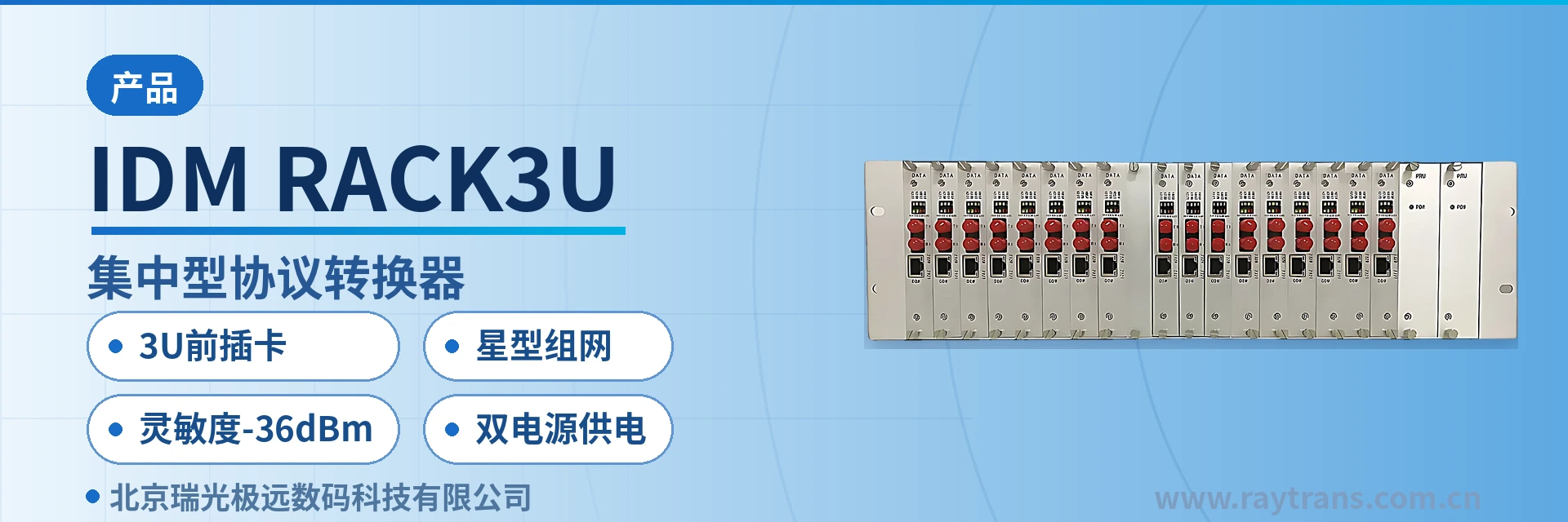
IDM-RACK3U Centralized Protocol Converter
17 remote ends aggregated in one chassis, eight types of service cards mixed insertion, single board failure swap without service interruption
The centralized protocol converter adopts a 19-inch 3U front-loading card-based structure. Each card corresponds to one remote RS232/422/485 data optical multiplexer or single-E1 bridge (optical modem), E1 optical multiplexer, high-speed serial optical modem, fiber optic switch, serial-to-bidirectional HDMI converter, telephone optical multiplexer, or E1 (V.35) optical modem, and can easily form a star network. The IDM-RACK3U centralized protocol converter makes full use of the large amount of existing E1/optical fiber resources in telecommunications networks to extend the transmission distance and application scope of Ethernet, providing a better solution for Ethernet access. This product can be used in local area
The IDM-RACK3U centralized protocol converter is a 3U front-loading card centralized protocol converter developed by Beijing Ruiguang Jiyuan Digital Technology Co., Ltd. (Raytrans), designed to aggregate serial port data, E1, telephone and Ethernet services from remote stations into a single chassis. Each plug-in card corresponds to one remote optical multiplexer or single-E1 bridge converter, and a fully configured chassis can connect to 17 remote stations, bringing the central node of a star network into one 3U device. As a professional optical multiplexer manufacturer, Raytrans has achieved an organic combination of product showcase and government private network optical fiber communication solution in this product.
Key Specifications at a Glance: 3U front-loading card · star networking · sensitivity -36dBm · dual power supply · 20 slots (2 power cards + 17 service cards + 1 network management card) · 155M optical interface · line-rate 100M Ethernet · overall power consumption ≤350W
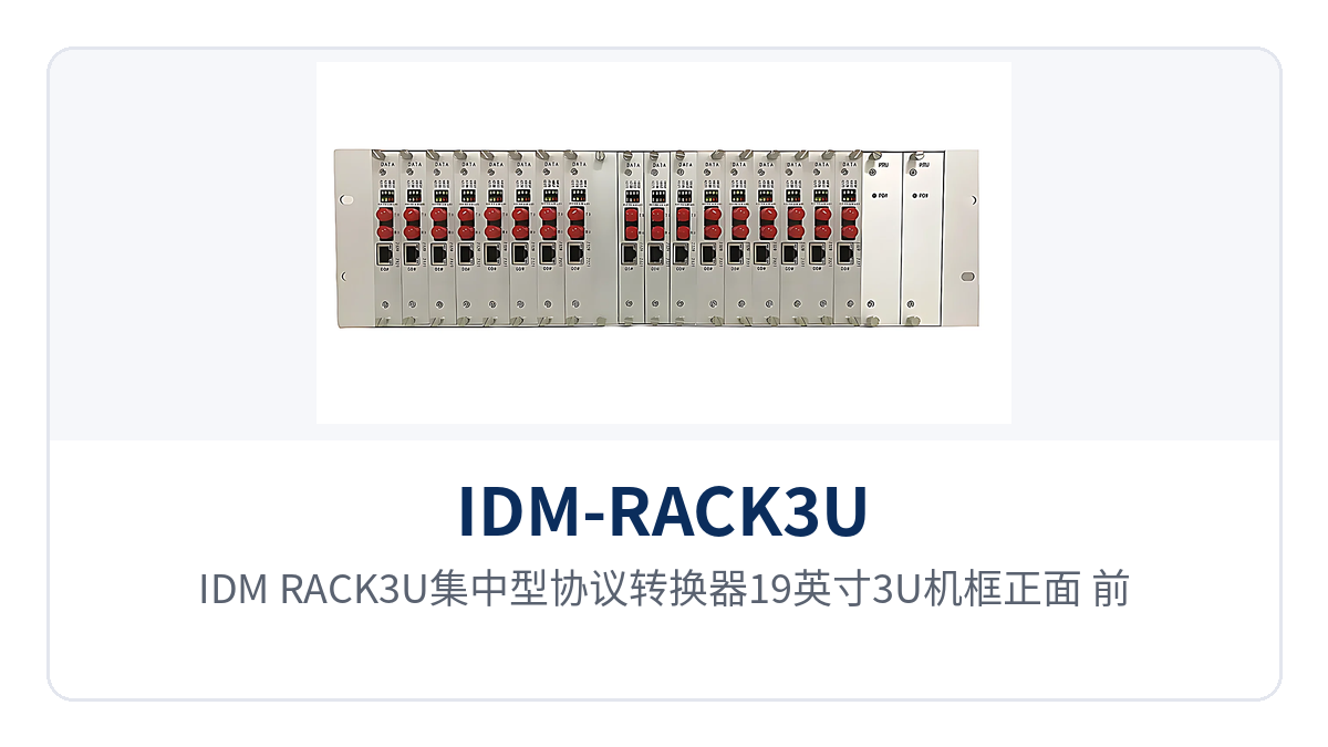
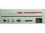
Figure 1: Front view of the 19-inch 3U chassis of the IDM-RACK3U centralized protocol converter, close-up of front-loading card slots and power alarm indicator LEDs
What kind of device is the 3U front-loading card centralized protocol converter?
The value of a centralized protocol converter lies in transforming point-to-point links into a star structure: a desktop optical multiplexer or bridge converter is placed at the remote end, a multi-slot chassis is placed in the central equipment room, and the services of each remote end return along their own optical fiber or E1 circuit to be aggregated uniformly in the chassis. The remote station needs only one small device, while the equipment count and cabling on the equipment room side are concentrated within a 19-inch rack; capacity expansion is done by adding cards rather than replacing the entire unit.
The IDM-RACK3U centralized protocol converter makes the central side a front-loading card structure, with service cards inserted from the front of the chassis and the panel carrying operating indication and alarm indication. In the event of a single board failure, the card can be pulled out and replaced while services on the other cards continue to run normally; maintenance actions are completed at the front of the chassis without dismantling the unit or re-cabling.
The chassis provides 20 slots, including 2 power card slots, 17 service card slots, and 1 network management card slot or service expansion card slot. Slots are gradually populated according to the number of remote ends on site; fewer cards are configured initially and added later as sites grow, keeping the investment pace consistent with the service provisioning pace.
How many remote devices can one chassis connect to?
With 17 service cards fully configured, one chassis can connect to 17 remote devices, with each service card corresponding to one remote direction. Service cards are selected according to the remote type, and mixed insertion of different types is allowed within the same chassis: whichever type of desktop device is already deployed at the remote site, the corresponding card is configured on the central side, without changing the existing remote configuration.
The correspondence between the eight types of service cards and remote devices is as follows, and the configuration list is checked site by site according to the actual service type of each remote station. Different types of service cards can be mixed within the same chassis, each occupying an independent card slot and backplane channel, and the services do not interfere with one another.
- RS232/422/485 data optical multiplexer card: corresponds to a remote desktop data optical multiplexer, carrying serial port data over long distances;
- Single-E1 bridge (optical modem) card: corresponds to a remote single-E1 bridge converter, extending Ethernet services over an E1 circuit;
- Single-E1 optical multiplexer card: corresponds to a remote single-E1 optical multiplexer, with E1 services directly connected over optical fiber;
- High-speed serial optical modem card: corresponds to a remote high-speed serial optical modem, carrying high-speed serial services;
- Fiber optic switch card: corresponds to a remote fiber optic switch, providing Ethernet fiber access;
- Serial port to bidirectional HDMI card: corresponds to a remote serial port to bidirectional HDMI device, transmitting serial port control and bidirectional video;
- Telephone optical multiplexer card: corresponds to a remote telephone optical multiplexer, providing service according to FXO/FXS interfaces;
- E1 (V.35) optical modem card: corresponds to a remote E1 (V.35) optical modem, with V.35 data transmitted over E1.
| Card slot type | Quantity | Description |
|---|---|---|
| Power card | 2 | Dual power cards supply power with 1+1 mutual backup; if one card fails, the other continues to carry the load |
| Service card | 17 | Each card corresponds to 1 remote device; a fully configured chassis connects to 17 remote directions |
| Network management card | 1 | A service expansion card can also be inserted, selected according to the expansion needs of the site |
| Total slots | 20 | Front-loading cards in a 19-inch 3U chassis; service cards support online replacement |
What functions does the centralized protocol converter have?
The chassis functions are organized around centralized aggregation and centralized management. Service capabilities are determined by the inserted service cards, common capabilities are provided uniformly by the chassis, and the chassis itself handles power supply, network management and slot hosting. The following function items are listed by chassis and service card; check them item by item when preparing the configuration list to avoid missing a power card or network management card.
| Function | Description |
|---|---|
| 3U front-loading card structure | 19-inch 3U chassis; service cards and power cards are inserted from the front, with slots corresponding one-to-one to card positions |
| One card per remote end | Each service card corresponds to 1 remote optical multiplexer or bridge converter, and remote faults are located down to the card |
| Mixed insertion of eight service card types | Data, single-E1 bridge, single-E1 optical multiplexer, high-speed serial, fiber optic switch, HDMI, telephone and E1 (V.35) cards can be mixed in the same chassis |
| E1 loopback test | Supports E1 local loopback and remote loopback to determine segment by segment whether a fault lies on the central side, the line or the remote side |
| Framed and unframed | Supports framed and unframed modes; framed mode supports PCM30/31 and CRC-4 adaptive |
| Dual network management channels | Serial port (RS485) network management and Ethernet network management, used to configure operating parameters and monitor operating status |
| Dual power card supply | Two power cards with 1+1 mutual backup; a single card failure in the power supply path does not affect service card operation |
| Ethernet line-rate forwarding | Ethernet interfaces comply with IEEE802.3, full/half duplex adaptive, with WAN transmission rate up to line-rate 100M |
Key specifications and interface specifications
The parameters of the optical interface, Ethernet interface, telephone interface and power supply environment are as follows; take values from the table when checking the configuration list against equipment room conditions. Transmission distance is jointly determined by transmit optical power, receiver sensitivity and on-site optical cable attenuation, and is calculated section by section according to the optical power budget in engineering practice.
| Item | Parameter/Specification | Description/Applicable Conditions |
|---|---|---|
| Interface type | FC (SC and others can be customized) | Selected according to the on-site optical distribution frame and patch cord interface |
| Fiber mode | Single-mode (multi-mode optional) | Single-mode for longer distances, multi-mode for short-distance interconnection within the equipment room |
| Optical fiber rate | 155bps±50ppm | Corresponds to the 155M optical transmission capability of the unit; the factory nominal value is subject to product documentation |
| Wavelength | 1310nm | Conventional transmission window of single-mode fiber |
| Transmit optical power | -2~-11dBm | Transmit optical power range, used to calculate the optical power budget |
| Receiver sensitivity | Better than -36dBm | Lower limit at which the receiver can receive data normally, with margin remaining on weak optical links |
The Ethernet interface parameters are as follows; the RJ-45 ports on each Ethernet service card connect to switches, routers or video devices according to this specification. Interface rate and duplex mode can be adjusted on site; when connecting to a switch, adaptive is generally set to avoid negotiation failure caused by inconsistent fixed configurations at both ends.
| Item | Parameter/Specification | Description/Applicable Conditions |
|---|---|---|
| Interface type | RJ-45 | Standard Ethernet electrical interface |
| Transmission rate | 10/100Base-T, 10M/100M | Rate can be matched to on-site devices |
| Standard protocol | Supports IEEE802.3 | Interoperates with conventional Ethernet devices |
| Operating mode | Full/half duplex/adaptive | Adaptive is usually set when connecting to a switch |
| WAN transmission rate | Line-rate 100M | Forwarding capability when Ethernet services are extended over E1 or optical fiber channels |
The telephone service card provides FXO and FXS interfaces, and voice parameters follow the specifications below. Select an FXO card when the central side connects to the switching office side, and an FXS card when connecting to the telephone or subscriber line side; verify voice quality standards before connecting to an SPC exchange or ordinary telephone to avoid excessive echo and attenuation.
| Item | Parameter/Specification | Description/Applicable Conditions |
|---|---|---|
| Audio range | 300Hz~3400Hz | Telephone voice band |
| Impedance | Three-element complex impedance 200Ω+560Ω//0.1μF | Return loss characteristics of the telephone interface |
| Compression | ITU G.711 A-law | Voice encoding method, 64Kbps standard voice channel |
| Loop current | 25mA/channel | Feeding capability for the telephone set |
The power supply, environmental and chassis parameters are as follows; check these conditions item by item before selecting the equipment room location, installing in the cabinet and connecting power. Overall power consumption is taken at full configuration of 17 service cards; reserve equipment room power capacity and air-conditioning load according to this figure, and choose either -DC48V or AC 220V according to on-site power conditions.
| Item | Parameter/Specification | Description/Applicable Conditions |
|---|---|---|
| Power supply mode | -DC48V or AC 220V (external) | -48V is taken in communications equipment rooms; AC 220V is taken in stations and office equipment rooms |
| Overall power consumption | ≤350W | Upper limit of overall power consumption at full configuration of 17 service cards |
| Operating temperature | 0℃~+50℃ | Equipment room and attended site environment |
| Humidity | 95% non-condensing | Relative humidity requirement |
| Product dimensions | 483×70×132mm (Length×Depth×Height) | 19-inch 3U chassis, installed in a standard cabinet |
As a professional optical multiplexer manufacturer, Raytrans fully presents the configuration logic and slot planning of the above eight types of service cards in the product showcase of the centralized protocol converter, making it easy for users to check site by site when selecting a government private network optical fiber communication solution. The mixed insertion capability of multi-service optical multiplexers and telephone optical multiplexers enables the same chassis to carry data, voice and video services simultaneously, while the bridge converter is responsible for backhauling remote Ethernet services over E1 circuits to the central side for unified aggregation; the complete chassis undertakes the centralized aggregation role of the central equipment room in the government private network optical fiber communication solution.
How is star networking deployed?
The deployment sequence for star networking is "determine central slots first, then remote card types, and finally check optical power and power supply." One IDM-RACK3U centralized protocol converter is placed in the central equipment room, one desktop device is placed at each remote station, one optical fiber or one E1 circuit corresponds to one remote direction, and services are aggregated uniformly on the central side. As a centralized model among bridge converter products, this device undertakes the multi-service aggregation role on the central side in the government private network optical fiber communication solution.
Proceed on site in the following order; completing selection, power supply verification and optical power calculation once before service provisioning can reduce rework. If the list is incompletely registered or the power budget is missed, problems often only surface when services are connected, at which point the cost of changes is noticeably higher.
- Compile a site list of remote stations, register the service type of each site (serial port, E1, Ethernet, telephone, V.35, HDMI), and determine which type of card each site needs;
- Determine the number of service cards and slot margin according to the number of sites, reserving several empty slots for later capacity expansion;
- Verify the power supply conditions of the central equipment room, select -DC48V or AC 220V external power supply, and confirm that the two power cards are fed from different power branches;
- Calculate the optical power budget according to the length of each optical cable section and the number of connectors, and confirm that the received optical power is above the -36dBm sensitivity lower limit;
- Provision card by card, verify segment by segment with E1 local loopback and remote loopback, and connect services only after confirming that the central side, the line and the remote side are all normal.
The remote station equipment is small in size and flexible in installation position; service-side interfaces are connected once at the remote end, and the central side only adds one card to the chassis. When a site is expanded, the center does not add cabinets or rearrange patch cords; it simply adds cards in the remaining slots, which is especially convenient in private network projects with distributed sites and year-by-year additions. For scenarios requiring unified aggregation by multi-service optical multiplexers, one chassis can cover the service showcase and access requirements of multiple remote directions.
Typical application scenarios
Electric power private network: centralized access for substations and power supply stations
Sites of the electric power private network are distributed across substations, power supply stations and switching stations, where there is both serial port data from protection and measurement and control devices and dispatch telephone and office Ethernet. A desktop device is placed at each remote station; serial port data returns via the RS232/422/485 data card, voice channels via the telephone card, and IP services via the Ethernet card to the equipment room of the power supply company, where a single 3U chassis aggregates them uniformly. Telephone optical multiplexer cards and data cards are mixed in the same chassis, and services of each station do not interfere with one another.
Electric power communication equipment rooms mostly use -48V DC power supply. The chassis supports -DC48V input and is equipped with two power cards, connecting to the existing DC distribution panel in the equipment room. Optical cables laid in earlier years have many connectors and relatively high attenuation, so the optical power at the receiving end often falls near the sensitivity. The -36dBm receiver sensitivity still allows such old optical fiber links to receive data stably without replacing the entire optical cable.
Rail Transit: Weak Optical Links at Stations and Substations Along the Line
Communication nodes of rail transit are distributed along the line, with long distances and many nodes among stations, substations, depots and the control center. On the central side, one 3U chassis aggregates the serial port, E1 and Ethernet services of each station. Each station is equipped with service cards selected according to service type, and the sites do not interfere with one another. A failure at a single station affects only the corresponding card. The card slots of the multi-service optical multiplexer are allocated by station, and telephone, data and Ethernet services run in parallel on the same platform.
Optical cable sections along the line are long and have many patch points. After attenuation and connector loss accumulate, they can easily press down to the lower limit of receiver sensitivity. A receiver sensitivity better than -36dBm leaves margin for such links. Station equipment rooms generally have AC 220V power supply conditions, so an external AC 220V power supply is sufficient for rack mounting. The overall power consumption of the chassis is ≤350W, which is within the power supply and heat dissipation capacity of ordinary station cabinets.
Military and Government Private Networks: Voice and Data Backhaul for Dispersed Sites
Between the central node and dispersed sites of military and government private networks, E1 circuits or optical fiber resources often already exist, and the services are mainly voice, serial port data, V.35 data and internal Ethernet. A remote station is equipped with one desktop device according to its services, and the central equipment room uses a 3U chassis for centralized termination. This makes use of existing transmission resources and reduces the number of central-side devices to one rack-mounted device. In government private network optical fiber communication solutions, this star topology significantly simplifies equipment display and O&M management on the equipment room side.
Field sites and temporary command posts have unstable power supply conditions. The chassis supports -DC48V or external AC 220V power supply, which can be selected according to on-site power supply conditions. Equipment rooms and field sites are delivered on the same platform, with unified spare parts and operating methods. RS485 serial port network management and Ethernet network management run in parallel, allowing on-duty personnel to remotely read the operating status of each card at the center and reducing the number of maintenance trips to the site. As an optical multiplexer manufacturer, Raytrans provides complete support from product showcase to solution implementation in such private network projects.
Selection and Deployment Recommendations
Selection is determined item by item according to four factors: number of remote stations, service type, optical cable conditions and power supply conditions, and the complete configuration can then be finalized. As a centralized model in the bridge converter category, the card slot allocation corresponds one-to-one with the remote site list, and the configuration table can be used directly as the basis for purchase and construction.
- The number of sites determines the number of service cards. Configure cards according to the existing number of sites plus a certain margin, and reserve the margin as empty slots;
- The service type determines the card type. Mixed insertion of different cards in the same chassis covers services such as serial port, E1, Ethernet, telephone and V.35;
- Optical cable conditions determine the interface and power budget. Select FC or SC interfaces according to on-site patch cords, and calculate before enabling links with high attenuation;
- Power supply conditions determine the power supply configuration. Use -DC48V in communications equipment rooms and AC 220V in stations and office equipment rooms, with the two power cards connected to different branches;
- The network management mode is selected according to O&M habits. Serial port (RS485) network management is used for local commissioning, and Ethernet network management is used for centralized monitoring at the center.
Three points also need attention on the equipment room side: the chassis is 19-inch 3U high, 70mm deep and 132mm high, so cabinet depth and load-bearing capacity must be checked in advance; the operating temperature is 0℃~+50℃ and the humidity is 95% non-condensing, so the equipment room environment must be improved if these ranges are exceeded; both service cards and power cards are front-inserted, so space for insertion, removal and maintenance must be reserved at the front of the cabinet. Raytrans can provide selection lists and product showcase materials to assist with configuration verification.