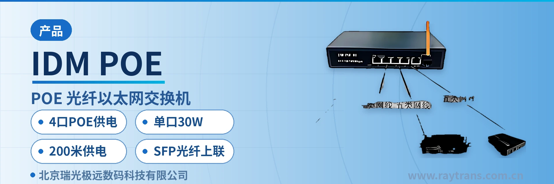
IDM POE-M4 PoE Fiber Uplink Switch
4-port 30W power supply, SFP fiber uplink, 200 m per-port power supply, saves power cables
The IDM POE-M4 PoE fiber optic Ethernet switch has 4 PoE-powered RJ45 ports and 1 RJ45/1 SFP fiber module expansion slot, and supports RJ45/SFP port uplink. All 4 RJ45 ports support IEEE 802.3af/at standard PoE power supply, with a maximum per-port power supply of 30W and a maximum overall power of 65W. It can automatically detect and identify powered devices compliant with the IEEE 802.3af/at standard and supply power over the network cable via the priority mechanism.
The IDM POE-M4 4-port PoE fiber uplink switch is an access-layer industrial switching device developed by Beijing Ruiguang Jiyuan Digital Technology Co., Ltd. (Raytrans). It integrates 4 PoE power supply RJ45 ports, 1 RJ45/SFP expansion slot and Fast Ethernet switching in the same chassis, and is used in an optical fiber access network to simultaneously transmit data and power to remote terminals over a single network cable. It is a typical product showcase from a media converter manufacturer for access-layer networking.
Front-end sites in industrial environments are often distributed across plant roads, towers, perimeter fences and field enclosures, where cameras and wireless APs need both local power supply and data backhaul to the center. The IDM POE-M4 combines power supply and data onto a single network cable and then uplinks to the optical fiber backbone through an SFP optical port, so the front end does not need a separate power supply cable, and enclosure space and construction workload are reduced accordingly. As an access-layer device from an industrial Ethernet switch manufacturer, this model can work with fiber optic switches and media converters, and widely serves scenarios such as POE network camera surveillance, POE WIFI coverage and POE network broadcast systems.
Key Specifications at a Glance: 4-port POE power supply · SFP fiber uplink · 30W per port · 200 m power supply · 65W overall · -10~55℃ wide temperature · IEEE 802.3af/at
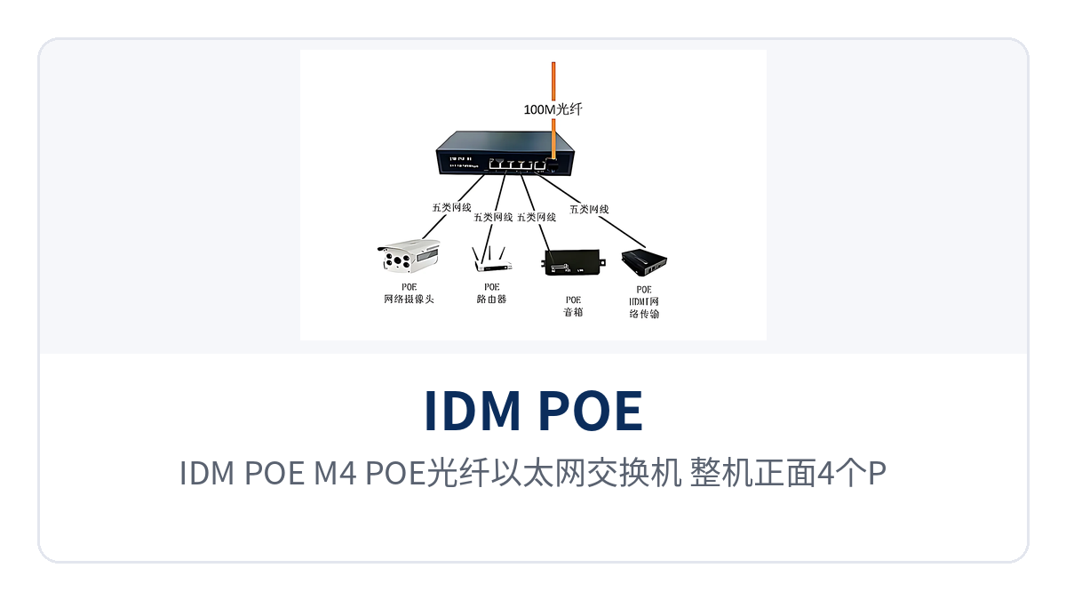
Figure 1: IDM POE-M4 POE fiber optic Ethernet switch — close-up of the 4 PoE power supply RJ45 ports and 1 SFP fiber slot on the front panel
What Kind of Device Is a 4-Port PoE Fiber Uplink Switch?
This device consists of 4 10/100M adaptive RJ45 electrical ports, 1 RJ45/SFP expansion slot and a MAC address table with a capacity of 1K. It adopts a store-and-forward mechanism and has a backplane bandwidth of 1Gbps. All 4 electrical ports support IEEE 802.3af/at standard PoE power supply, with a per-port power supply upper limit of 30W and an overall power supply budget upper limit of 65W; the PoE power supply transmission distance reaches 200 m as stated in the original product documentation. As a compact product showcase solution, it integrates power supply, switching and optical uplink in a single device, making it suitable as a front-end access node in media converter application scenarios.
The uplink side provides 1 RJ45/SFP expansion slot; inserting an SFP optical module provides seamless interfacing with the optical fiber backbone, and the RJ45 port can also be used for electrical-port uplink. The device requires no configuration and is plug-and-play. Its overall power consumption upper limit is 65W, its dimensions are 200mm×120mm×40mm and its weight is 1kg, and it can be mounted in a weak-current box or a field enclosure. For projects that need to aggregate IP terminals nearby, this type of design is also often included in the selection scope of fiber optic switches.
What Services Can 4 POE Power Supply Ports and an SFP Fiber Uplink Carry?
The functions of the IDM POE-M4 revolve around three main lines: power supply, switching and optical uplink. The following table lists the role and applicable conditions of each capability by function item, making it easy to check against the on-site terminal list item by item and to finalize the power supply budget and uplink mode at the selection stage in one pass.
| Function | Description |
|---|---|
| 4-port POE power supply | Ports 1 to 4 all support IEEE 802.3af/at standard PoE power supply, with a per-port power supply upper limit of 30W and an overall upper limit of 65W, and can supply power over the network cable to powered devices such as cameras and wireless APs |
| Intelligent power identification | The ports have PoE identification capability; when the power of a powered device exceeds the IEEE 802.3af standard, the system automatically activates the IEEE 802.3at standard and supplies power to the port according to the power supply priority mechanism |
| SFP fiber uplink | 1 RJ45/SFP expansion slot; inserting an SFP optical module provides seamless interfacing with the optical fiber backbone, and it can also be switched to RJ45 electrical-port uplink |
| Port adaptive | Each port supports MDI/MDIX auto-crossover and auto-negotiation, the electrical ports are 10/100M adaptive, and network cables require no manual patch cord regardless of polarity |
| Flow control | Supports IEEE 802.3x full-duplex flow control and half-duplex backpressure flow control, which together with store-and-forward reduces packet loss under high concurrency |
| MAC address management | A MAC address table with a capacity of 1K, supporting automatic MAC learning and aging, with ports forwarding quickly according to the power supply priority mechanism |
| Status indication | Each port is provided with 1 LINK/ACT indicator LED, plus a POE Status indicator LED and an overall power indicator LED, so port and power supply status can be judged on site |
Key Specifications and Performance Specifications
The three categories of specifications — power supply, uplink and switching — are organized below as stated in the original product documentation. The parameter table answers what the device can achieve and under what conditions, and can be used directly on site to check against powered device power and link conditions. Parameter values are subject to the manufacturer's technical documentation; engineering calculations should also take cable voltage drop and enclosure ambient temperature into account.
| Item | Parameter/Specification | Description/Applicable Conditions |
|---|---|---|
| PoE ports | Ports 1 to 4 support IEEE 802.3af/at | All 4 RJ45 ports support PoE power supply |
| PoE port output power | 15.4W (IEEE 802.3af) / 30W (IEEE 802.3at) | Per-port power supply upper limit |
| PoE total power | ≤65W | Overall power supply budget, allocated among ports as required |
| PoE connection standard | IEEE 802.3af / IEEE 802.3at | PoE type is end-span |
| PoE power transmission wire pairs | 1/2+, 3/6- wire pairs | 4/5+, 7/8- wire pairs available on order |
| POE power transmission distance | ≤200 m | As stated in the original product documentation, power supply side |
| Network signal distance | ≤100 m | Twisted-pair Ethernet signal transmission |
| Item | Parameter/Specification | Description/Applicable Conditions |
|---|---|---|
| Network standards | IEEE 802.3, IEEE 802.3u, IEEE 802.3x, IEEE 802.3af/at | Switching and power supply standards |
| Network medium | 10/100BASE-TX: Category 5 or above unshielded twisted pair | Electrical port cabling requirements |
| Electrical port rate | 4 10/100M adaptive | High-speed data forwarding without packet loss |
| Optical fiber port | 1 SFP expansion slot | Uplink to the optical fiber backbone |
| Backplane bandwidth | 1Gbps | As stated in the original product documentation |
| Forwarding mode | Store-and-forward | Forwarding rate 14880PPS/port for 10BASE-T, 14800pps/port for 100BASE-TX |
| MAC address table | 1K | Supports automatic MAC learning and aging |
| Input power | AC 100-240V 50/60Hz | Wide-range AC input |
| Overall power consumption | 65W with power supply | As stated in the original product documentation |
| Operating temperature | -10℃~55℃ | Field enclosures and unattended environments |
| Weight and dimensions | 1kg; 200mm×120mm×40mm (L×W×H) | In-cabinet installation in weak-current boxes and cabinets |
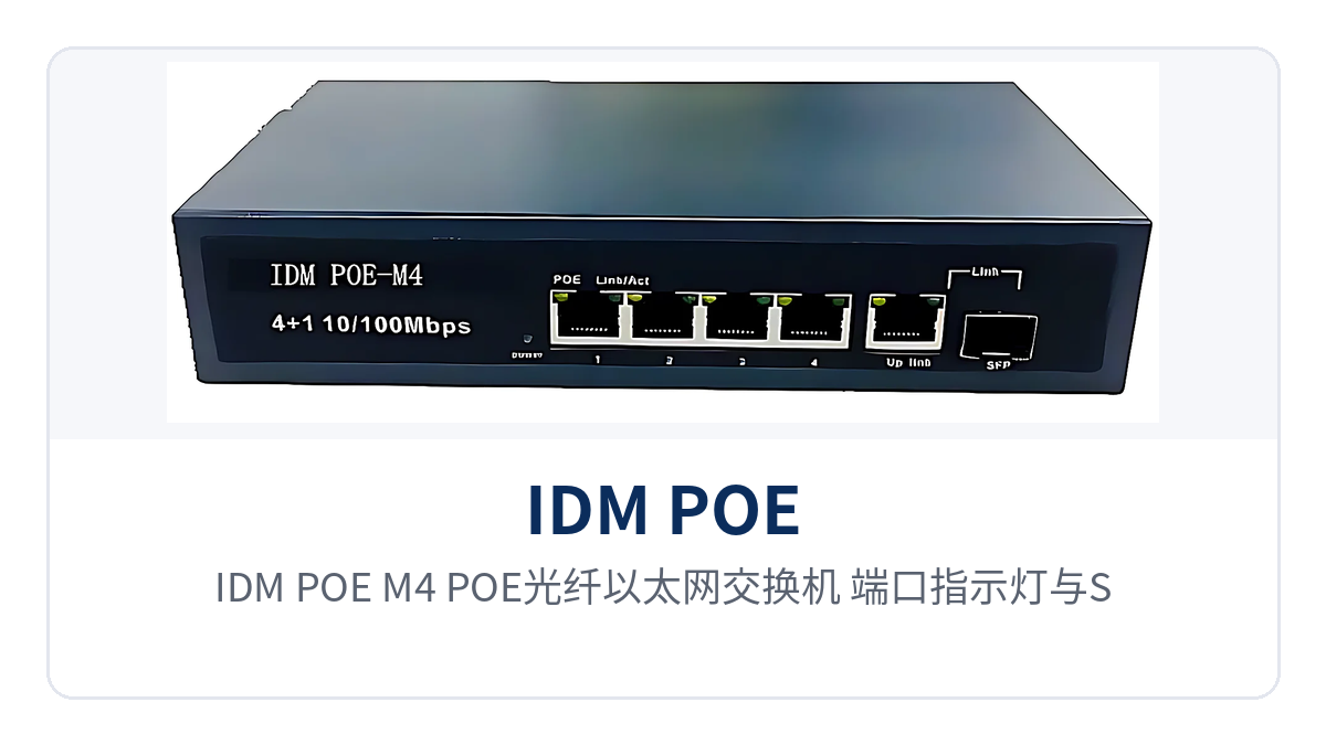
Figure 2: IDM POE-M4 POE fiber optic Ethernet switch — port indicator LEDs and SFP optical port uplink, installation schematic inside a surveillance pole enclosure at an industrial site
What Do the Three Differentiation Points Mean for Industrial Sites?
The three capabilities only become meaningful when applied to cabling, power supply and environmental conditions. The following table maps each differentiation point to the project benefits at an industrial site item by item, making it easy to judge at the solution stage whether the device matches the actual on-site conditions. The left column lists device-side specifications, and the right column lists the corresponding practices and results in construction and O&M; the two should be checked in pairs.
| Differentiation Point | Value to the Project |
|---|---|
| POE power supply transmission distance up to 200 m | Breaks through the 100 m cabling limit at industrial sites: data and power share one network cable, so surveillance poles, perimeter fences and field enclosure sites do not need local power supply access, and the 200 m POE power supply transmission distance allows access points to be deployed further forward |
| 30W per port, 65W overall | Meets the high-power powered device needs of industrial cameras and APs: 30W per port can drive infrared cameras, PTZ cameras and high-power wireless APs, and within the 65W overall power supply budget the 4 ports are allocated according to the priority mechanism, so the front-end enclosure does not need an additional power supply module |
| -10℃~55℃ operating temperature | Adapts to unattended field enclosure environments: the wide-temperature specification covers summer exposure and winter low temperatures, and together with the AC 100-240V wide-range input, the device can be installed directly in pole-mounted enclosures and workshop distribution boxes for long-term operation |
What Is the Relationship Between the 200 m POE Power Supply Transmission Distance and the 100 m Network Signal Distance?
PoE power supply is defined by the IEEE 802.3 series of standards. IEEE 802.3af specifies a per-port power supply of about 15.4W, and IEEE 802.3at (PoE+) raises this to 30W; the two determine whether a powered device can be identified and draw power. The 4 ports of the IDM POE-M4 implement power supply according to IEEE 802.3af/at, and ordinary non-PoE terminals will not be supplied with power by mistake when connected.
The product documentation gives the power supply distance and the network signal distance separately: POE power transmission distance ≤200 m, and twisted-pair Ethernet signal transmission ≤100 m. In engineering practice, the data segment is planned at 100 m, and the power supply segment provides power to terminals within 200 m; when a site is farther away, the SFP optical port is first used to extend the optical fiber to a nearby point, and the device then supplies power locally over the network cable, with the coverage continuing to expand with the optical fiber length. In typical networking, this device can serve as a PoE uplink unit in a media converter manufacturer's product line, and can also work with industrial Ethernet switches and fiber optic switches to carry front-end services such as POE network camera surveillance, POE WIFI coverage and POE network broadcast systems; as an industrial Ethernet switch manufacturer, Raytrans provides complete support from product showcase to solution implementation around such scenarios.
Typical Application Scenarios
Industrial Security Surveillance: PoE Camera Power Supply and Optical Fiber Backhaul
Surveillance sites on plant roads, mining area perimeter fences and towers are far from the equipment room, and camera power supply and stream backhaul often require two separate cabling runs. The IDM POE-M4 is deployed at the surveillance aggregation point; its 4 PoE ports supply power to cameras over network cables and backhaul video, and the SFP optical port sends multiple video channels onto the optical fiber backbone. 30W per port can drive infrared and PTZ cameras, and the 65W overall budget is allocated among the 4 ports as required. As a typical application in the product showcase, this combination makes the cabling for POE network camera surveillance simpler.
A front-end enclosure usually has only one mains power feed, and fitting each camera with its own adapter makes the wiring inside the enclosure crowded. Once power supply and data are combined onto the same network cable, the enclosure needs only one device and one uplink optical fiber, and the point of failure and maintenance workload are reduced accordingly.
Industrial Wireless Coverage: Power Supply for Wireless APs and Private Network Nodes
Wireless APs high in workshops, on poles and on tower tops are difficult to power, and long-distance power runs both increase cost and introduce hazards. The IDM POE-M4 completes AP power supply and data backhaul over a single network cable, and the SFP optical port brings distributed wireless nodes into the same optical fiber private network; the -10℃~55℃ operating temperature and AC 100-240V input adapt to unattended field enclosure environments, providing stable power supply assurance for POE WIFI coverage scenarios.
Power requirements vary considerably among wireless coverage sites: an ordinary AP draws about 10W, while a dual-band high-power AP approaches 30W. The device ports have PoE identification capability; when the power of a powered device exceeds the IEEE 802.3af standard, the IEEE 802.3at standard is automatically activated and power is allocated according to the power supply priority mechanism, so compatibility need not be confirmed model by model.
Industrial IoT Sensing: Access of Edge Collection Terminals
Sensors, card readers and collection gateways in the Industrial IoT are numerous and draw little power per point, but they place high demands on power supply stability and maintenance-free operation. The IDM POE-M4 can automatically identify powered devices compliant with the IEEE 802.3af/at standard and supply power according to the priority mechanism; non-powered devices will not be supplied with power by mistake when connected, and the 4 ports can be allocated nearby by site. It is also suitable for edge access of POE network broadcast systems.
Front-end collection points often follow conveyor belts, pipe galleries, or perimeter walls in a linear layout, and the distance from each site to the access box varies. Remote ends beyond network cable coverage are reached by extending a stretch of optical fiber from an SFP optical port and then connecting nearby, and with power over Ethernet (PoE) and fiber uplink used in combination, the number of access boxes can be increased or decreased according to the actual site density.