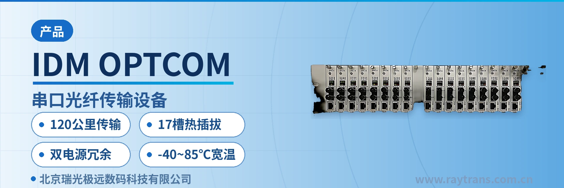
IDM OPTCOM Serial Port Fiber Optic Transmission Device
Jumper-Switched Three Serial Port Types, Single-Fiber Aggregation of Multiple Services, 120 km, 17-Slot Hot-Swappable Dual Power Supply
The serial port fiber optic transmission device has stronger anti-interference capability and is not affected by electromagnetic interference, lightning strikes, or ground loop problems, ensuring high reliability and security of data transmission. It supports multiple serial port protocols such as RS-232, RS-485, and RS-422; users can switch between different interface types via jumpers to adapt to diverse device communication requirements; serial port rate adaptive (0~115200 bps), automatically adjusting the rate to ensure transmission efficiency; the internal sampling frequency for RS-232, RS-485, and RS-422 services is 13 MHz; supports 1 channel of CTS and RTS control transmission
What Kind of Device Is the IDM OPTCOM Serial Port Fiber Optic Transmission Device?
The IDM OPTCOM serial port fiber optic transmission device is a serial port data fiber optic transmission device developed by Beijing Ruiguang Jiyuan (Raytrans). It is used to move RS-232, RS-485, RS-422, and USB serial port services from copper cables onto optical fiber, and to transparently restore them at both ends of the link. As a professional optical multiplexer manufacturer, Ruiguang Jiyuan has accumulated extensive product showcase and engineering application experience on this product series.
The device is configured in pairs of a central end and a user end: the central end is a 3U 19-inch rack-mounted structure, and the user end is a desktop box. The serial port data between the two ends is carried over a single optical fiber link, and the existing instrument, PLC, and industrial PC interfaces on site do not need to be modified. This optical multiplexer is often used as the core link device in industrial automation serial port fiber optic transmission solutions.
The device performs sampling and encoding on the serial port side and electrical-to-optical conversion on the optical side. The serial port rate is rate adaptive from 0 to 115200 bps; the link transmits at whatever baud rate the opposite-end instrument uses, so there is no need to configure separately for equipment from different manufacturers and different generations. The internal sampling frequency for RS-232, RS-485, and RS-422 services is 13 MHz, so both low-speed instruments and high-speed acquisition devices can be connected on the same board. As a multi-service optical multiplexer, the device can aggregate multiple serial port services on a single standalone unit.
Key specifications at a glance: RS-232/RS-485/RS-422 jumper switching · 0115200 bps rate adaptive · multiple services aggregated over a single fiber · transmission distance 120 km · 3U rack with 17 user board slots · dual power supply 1+1 protection · -4085℃
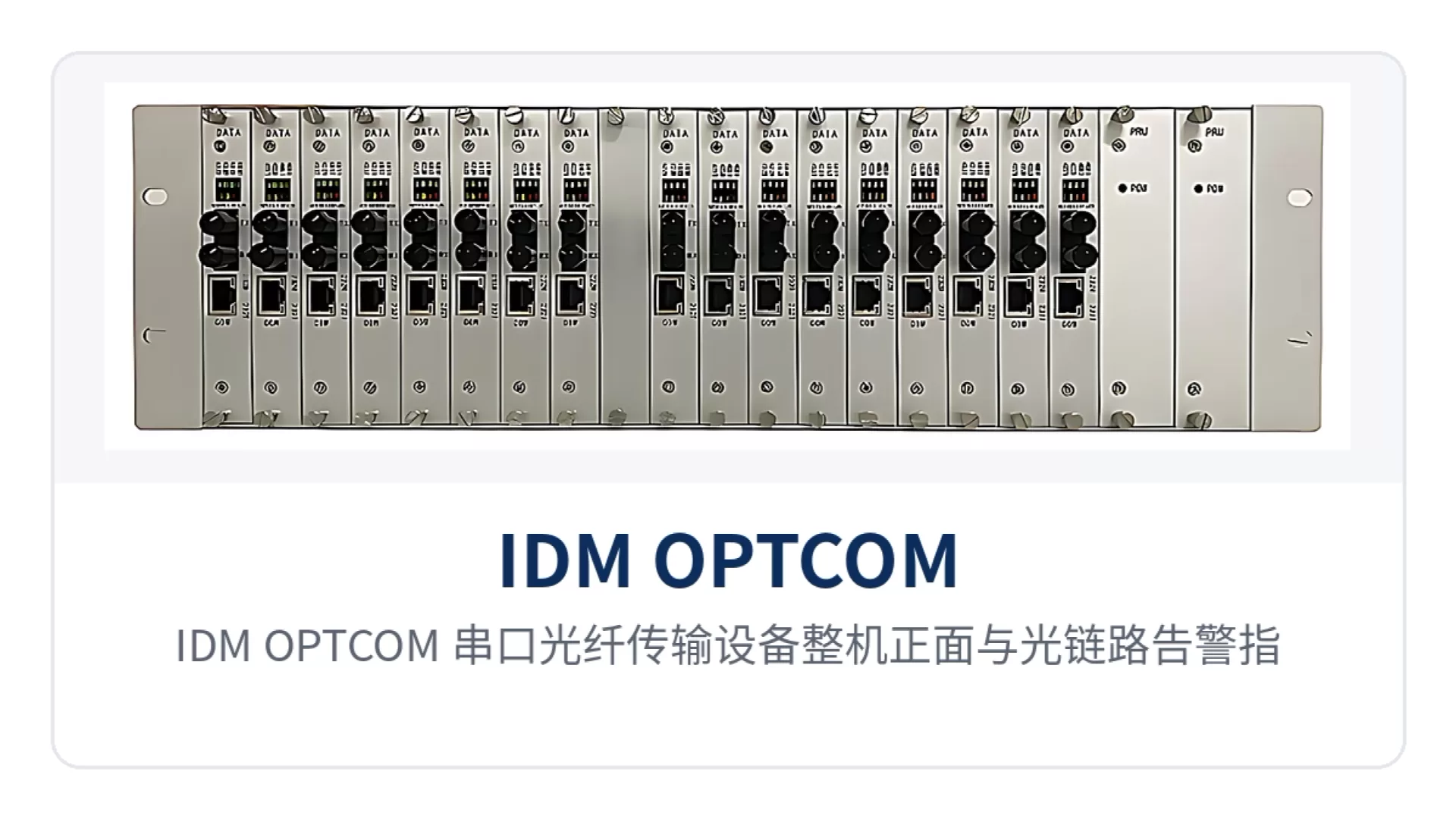
Figure 1: Front view of the IDM OPTCOM serial port fiber optic transmission device and optical link alarm indicator LEDs
The value of switching to optical fiber transmission comes down to three things. Optical signals are immune to electromagnetic interference, lightning strikes, and ground loops, so interfaces will not be burned out by ground potential difference between the two ends over long-distance links; the transmission distance is determined by the optical module, and the few hundred meters to several kilometers that copper cables cannot handle can be extended to 120 km over optical fiber; and one optical fiber can carry multiple serial port services, so a single uplink at the rack end can aggregate multiple remote sites. This is also why industrial serial port optical multiplexers are widely adopted at unattended sites, and they are equally applicable in electric power remote monitoring data transmission solutions and intelligent transportation communication solutions.
Four Capability Tags: 120 km Transmission, 17-Slot Hot-Swappable, Dual Power Supply Redundancy, -40~85℃ Wide Temperature
The four tags correspond respectively to transmission distance, rack expansion capability, power supply redundancy, and environmental adaptability. By checking these four items one by one on site, you can determine whether a device is sufficient and whether boards need to be added or optical modules replaced. Beyond the table below, the optical module model and the serial port type at both ends must also be confirmed when configuring an order, to avoid interface mismatches upon delivery.
| Differentiation Point | On-Site Value |
|---|---|
| 120 km transmission | Multiple serial port services aggregated over a single fiber, with a transmission distance of up to 120 km, breaking through the physical limits of copper cables; serial port devices across plants or sites no longer need additional repeaters |
| 17-slot hot-swappable | The 3U 19-inch rack provides 17 user board slots and 2 power supply slots; capacity expansion only requires plugging in a board, and hot-swapping does not interrupt the services in use on other boards |
| Dual power supply redundancy | Dual power supply 1+1 protection; the device continues to run when one power supply fails, so a single power supply failure at a substation or unattended station building does not stop all serial port services |
| -40~85℃ wide temperature | Operating temperature -40℃~+85℃, combined with ESD protection design on service interfaces, adapting to the temperature and interference conditions of outdoor cabinets, factory buildings, and field station buildings |
How Is 120 km Transmission Achieved
The transmission distance is not a fixed specification of the device itself but is jointly determined by the optical module and line conditions. The device supports optional single-mode and multi-mode optical interfaces; when configuring an order, select the module according to the optical cable length and attenuation between sites, and for long-distance links prioritize calculating the received optical power margin. The optical side supports multi-core fiber aggregation, and a single fiber can carry multiple data services, so the fiber core resources in one direction do not need to increase proportionally with the number of services.
How Does 17-Slot Hot-Swapping Enable Expansion
The central-end chassis is designed to the 3U 19-inch standard rack, and service boards can be inserted into the chassis, with each board carrying one serial port service and one USB serial port service. When service sites increase, simply add boards instead of purchasing another standalone unit; the boards are hot-swappable, so the services in use on the remaining boards are unaffected when maintaining or replacing a single board. The chassis also provides 2 power supply slots for dual power supply configuration.
How to Choose Among the Three Serial Port Protocols: Jumper Switching for RS-232, RS-485, and RS-422
The interface type is determined by the on-site device side, not by the transmission link. The device supports three serial port protocols: RS-232, RS-485, and RS-422, and users switch the interface type via jumpers; RS-485 fiber optic transmission and the RS-422 four-wire connection share the same board, so instruments, controllers, and acquisition terminals from different manufacturers can all be connected, and spare parts do not need to be split into three models by protocol, providing flexible interface adaptation capability for industrial automation serial port fiber optic transmission solutions.
| Interface Type | Electrical and Wiring Characteristics | Common On-Site Connection |
|---|---|---|
| RS-232 | Single-ended signal, with receive, transmit, and signal ground as a group | Point-to-point connection of commissioning ports on industrial PCs and instruments, short distance, one-to-one |
| RS-485 | Differential two-wire, supports bus daisy-chaining | Multiple instruments on one bus, with A and B polarity aligned at both ends |
| RS-422 | Differential four-wire, with receive and transmit separated | For controller applications requiring full-duplex, with the four wires connected separately |
Whichever type is selected, a single board can transmit 1 channel of RS-232, 1 channel of RS-485, or RS-422 data service, and can also carry 1 channel of USB serial port service. The device supports 1 channel of CTS and RTS control transmission interface, and the hardware flow control signals pass over the optical fiber together with the data, preserving the handshake relationship between the devices at both ends. The service interfaces adopt ESD protection design, so the interfaces are not easily damaged when serial port cables are plugged or unplugged while powered on site.
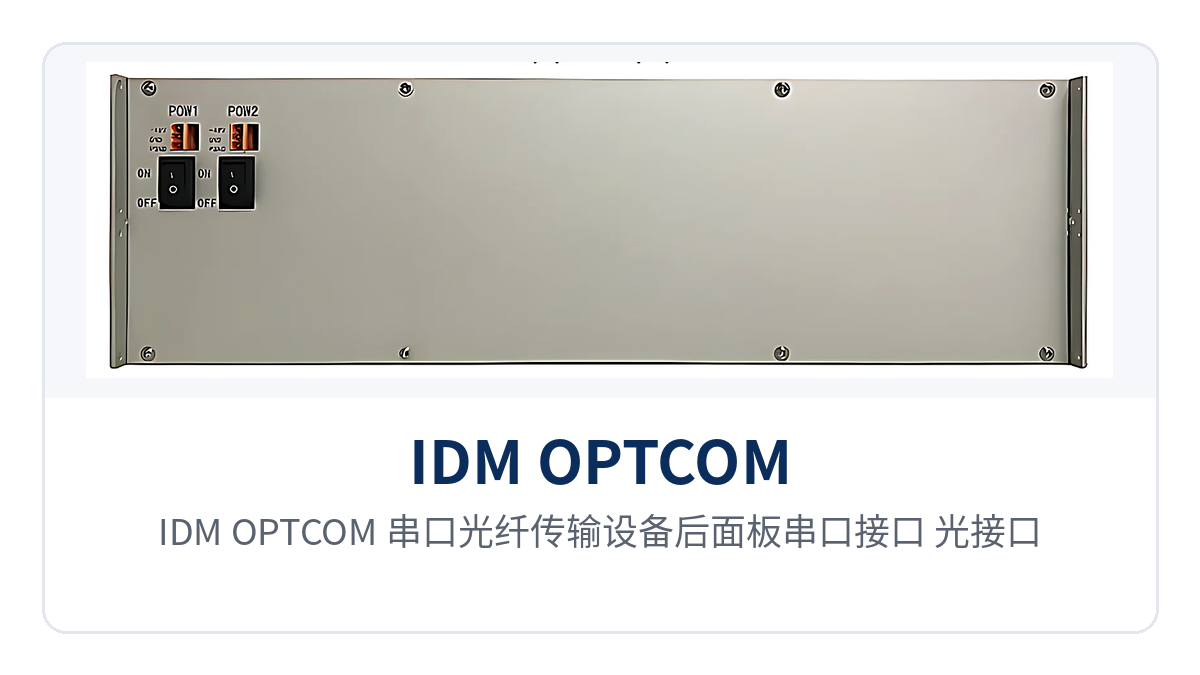
Figure 2: Rear panel layout of serial port interfaces, optical interfaces, and power input on the IDM OPTCOM serial port fiber optic transmission device
What Service Functions Can the IDM OPTCOM Carry?
The functions can be grouped into four categories: transmission, interfaces, monitoring, and maintenance, listed item by item in the table below. Each item in the table corresponds to an interface or indicator LED that can be checked on the panel, and can be directly referenced in bid lists and configuration sheets; on-site acceptance can also be checked item by item against this table without going through the entire manual.
Function Overview
| Function | Description |
|---|---|
| Optical fiber transmission and multi-core aggregation | Uses optical fiber transmission and supports multi-core fiber aggregation; a single fiber can carry multiple data services |
| Long-distance coverage | Transmission distance up to 120 km, depending on the selected optical module |
| Multiple serial port protocols | Supports RS-232, RS-485, and RS-422, with jumper switching of the interface type |
| USB serial port service | Configured on the same board as the serial port service, can transmit 1 channel of USB serial port service |
| Rate adaptive | Serial port rate rate adaptive from 0 to 115200 bps, automatically matching the rate of the opposite-end device |
| Control signal transparent transmission | Supports 1 channel of CTS and RTS control transmission interface |
| ESD-protected interfaces | Service interfaces adopt ESD protection design, adapting to on-site plugging and unplugging in industrial environments |
| Alarm indication | Status indication of no optical input (NOP), loss of frame (LOF), and remote alarm indication (RAI) |
| Data receive/transmit indication | RS-232/RS-485/RS-422 each have data receive/transmit indicator LEDs |
| Loopback test | Supports testing the serial port service at the local end or the remote end through the Type-C interface |
| Local commissioning | Provides an RJ45 interface for connection to a PC or other device for commissioning and maintenance |
| Hot-swappable chassis | 3U 19-inch rack with 17 user board slots and 2 power supply slots, supporting hot-swapping |
| Dual power supply redundancy | Dual power supply 1+1 protection; the device continues to run when a single power supply fails |
The purpose of the alarm design is to shorten the troubleshooting path. On the panel, NOP indicates no optical input, LOF indicates loss of frame, and RAI indicates remote alarm; these three statuses correspond respectively to a broken optical path, an abnormal frame structure, and a failure of the opposite-end device, so O&M personnel can narrow the fault scope to a link segment or a device just by looking at the LEDs in front of the cabinet, without first bringing instruments to the site. With the above capabilities, this series of optical multiplexers from Ruiguang Jiyuan (Raytrans) can broadly serve scenarios such as electric power remote monitoring data transmission solutions and intelligent transportation communication solutions.
Key Specifications: Optical Ports, Serial Ports, Power Supply, and Environment
The table below lists the main specifications grouped by interface, power supply, and environment. The values are taken from product documentation and can be quoted as-is in selection and bidding. Items in the table without marked test conditions should be understood as applying to an equipment room environment at normal temperature and humidity; for outdoor cabinets or high-temperature factory buildings, verify the temperature control conditions separately before finalizing the configuration.
Interface and Transmission Specifications
| Item | Parameter/Specification | Description/Applicable Conditions |
|---|---|---|
| Supported interfaces | RS-232 / RS-485 / RS-422 | Jumper switching of interface type; a single board can transmit 1 channel |
| Interface service capacity | 1 channel of RS-232, RS-485, or RS-422, plus 1 channel of USB serial port | According to the service board configuration |
| Transmission rate | 0~115200 bps rate adaptive | Automatically matches the rate of the opposite-end device |
| Internal sampling frequency | 13 MHz | Corresponds to RS-232, RS-485, and RS-422 services |
| Control interface | 1 channel of CTS, RTS | Hardware flow control signals pass over the optical fiber together with the services |
| Transmission distance | Up to 120 km | Depending on the selected optical module and line conditions |
| Optical fiber interface type | Multi-mode or single-mode optional | Selected according to on-site distance and fiber core conditions |
Structure and Power Supply Specifications
| Item | Parameter/Specification | Description/Applicable Conditions |
|---|---|---|
| Device type | Desktop box, rack-mounted | Configured separately for the user end and the central end |
| Rack structure | 3U 19-inch, 17 user board slots and 2 power supply slots | Supports hot-swapping; boards configured according to service sites |
| Power input | Desktop: DC12V; rack-mounted: DC5V or -48V to DC5V | Selected according to site power supply conditions |
| Power supply redundancy | Dual power supply 1+1 protection | Rack-mounted configuration; a single power supply failure does not affect operation |
| Operating temperature | -40℃~+85℃ | Wide-temperature design, adapting to outdoor cabinets and industrial sites |
| Alarms and indications | No optical input, loss of frame, remote alarm, plus serial port data receive/transmit LEDs | Panel indicator LEDs for on-site troubleshooting by LED status |
| Interface protection | Service interfaces adopt ESD protection design | Protects interfaces during on-site plugging and unplugging and in interference environments |
Typical Application Scenarios
The common requirements of the three industries for serial port links are long distance, high interference, and scattered sites; the differences lie in the service objects and reliability criteria. The following describes, by industry, which segment the device is connected to and what problem it solves, so that selection can refer to the scenario closest to your own situation.
Industrial Automation: Distributed Acquisition and Equipment Monitoring
Most PLCs, variable-frequency drives, weighing instruments, and legacy CNC equipment in a plant only have RS-232 or RS-485 ports, while the acquisition host is in the central control room, and copper cables reach the limits of distance and interference as soon as they cross the workshop. The IDM OPTCOM from Ruiguang Jiyuan (Raytrans) connects serial port services on the device side and sends them to the control room over optical fiber, so electromagnetic interference, lightning strikes, and ground loops no longer affect the data.
Distributed data acquisition systems and smart factory upgrades commonly use this connection: only one desktop box device is placed at the remote end, and boards are configured by site at the central-end rack. Rate adaptive serial port rates eliminate the need to change parameters one by one when old and new instruments are mixed, and the wide-temperature specification of the industrial automation serial port fiber optic transmission solution also covers workshops and factory building mezzanines without air conditioning.
Electric Power and Energy: Remote Monitoring of Substations and Distribution Networks
Remote monitoring of substations, distribution networks, and power plants relies on serial port backhaul of electric energy data, protection signals, and environmental parameters, and the common requirements for such links are low latency and long-term stability. The device provides point-to-point optical fiber channels with transparent transmission of serial port services, without changing the original protocols and frame formats, so the measurement and control devices and the backend on the access side do not need to be re-pointed, which meets the protocol transparency requirement of power remote monitoring data transmission solutions.
The rack-mounted central end aggregates the serial port services of multiple sites on the centralized control station side, and dual power supply 1+1 protection ensures that a single power supply failure does not affect the services in use. The wide-temperature design with an operating temperature of -40℃~+85℃, together with anti-static treatment of service interfaces, adapts to the operating conditions of switching stations, box-type substations, and field station buildings.
Intelligent Transportation: Monitoring and Field Device Data Backhaul
The monitoring devices, signal control devices, and data acquisition devices of an intelligent transportation system are distributed at intersections and road sections, where communication distances are long and power supply access conditions are poor, and lightning strikes and ground potential differences are common sources of failure. Once serial port data is carried over optical fiber, there is no longer an electrical connection between the intersection cabinet and the center, and such failures are cut off at the source, which is exactly a key part of link isolation in intelligent transportation communication solutions.
Multiple transmission lines can also be aggregated onto a single fiber core: multiple serial port services of one road section share one fiber core, which especially benefits the renovation of old urban areas with limited duct resources. The central end rack is configured with boards according to the number of intersections, and when a new intersection is added, boards are plugged in for capacity expansion without laying an entire new optical cable.
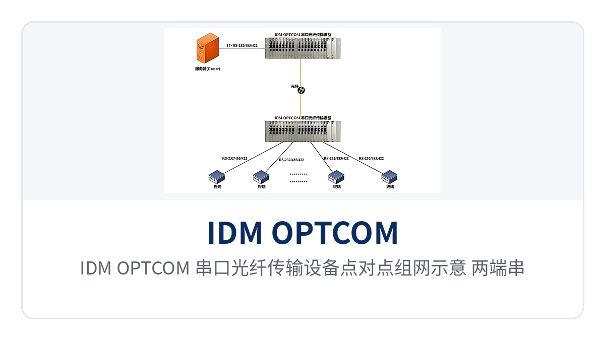
Figure 3: IDM OPTCOM serial port optical fiber transmission device point-to-point networking schematic, serial port devices at both ends transparently interconnected over optical fiber
How to Deploy Point-to-Point and Star Networking
The difference between the two networking approaches lies in whether the central end needs to aggregate. Point-to-point is suitable for a single link with one device at each end; star networking is suitable for aggregating multiple distributed sites into one equipment room, with one rack-mounted device at the central end as the aggregation point and a desktop box device at each remote end. Which one to choose depends on the number of sites and whether the equipment room has a 19-inch rack.
Point-to-point deployment requires only three steps: one device at each end, a pair of optical modules, and one optical fiber link. On the serial port side, select the type according to the on-site device and set the jumpers properly; rate adaptive requires no setting, and after power-on, check whether the data receive/transmit indicators on the front panel are flashing to determine whether the link is up. If the link is down, first check NOP and LOF, then determine whether the problem is the optical path or the opposite-end device.
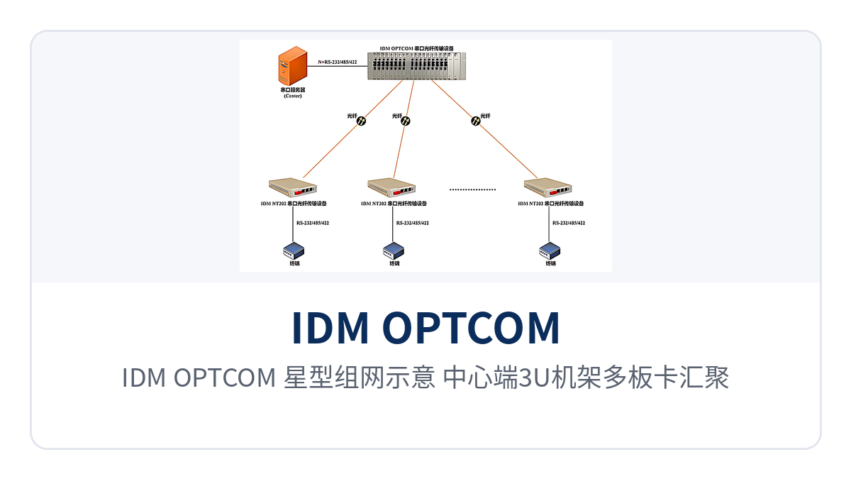
Figure 4: IDM OPTCOM star networking schematic, central end 3U rack with multiple boards aggregating multiple remote serial port sites
The key to star deployment lies in board configuration and optical fiber management at the central end. The central end is configured with service boards according to the number of remote sites, each site occupying one board and one optical fiber, and the 17 slots in the chassis determine the number of sites that a standalone unit can aggregate; when services are expanded, boards are plugged in, and hot-swappable capability means the unit does not need to be stopped. The remote desktop box device is small and can be placed directly in an instrument cabinet or communication box.
Conclusion
The IDM OPTCOM serial port optical fiber transmission device from Raytrans (Beijing Ruiguang Jiyuan Digital Technology Co., Ltd.) brings RS-232, RS-485, RS-422, and USB serial port services into the same optical fiber link, with the central end aggregating in a 3U rack and the user end positioned as a desktop box; serial port rate adaptive means that when old and new devices are mixed, parameters do not need to be changed one by one. As a product showcase-grade serial port optical multiplexer launched by an optical multiplexer manufacturer for industrial sites, it makes distance, expansion, and power supply redundancy simultaneously configurable; for users who need the multi-service optical multiplexer form, serial ports and other services can also be combined by board combination, and the PDH transmission system provides a stable channel foundation for the link.
The transmission distance can reach 120 km, the 17 user board slots in the rack support hot-swappable operation, and dual power supply 1+1 protection and -40℃~+85℃ wide temperature cover the operating conditions of substations, plants, and intersection cabinets. When configuring an order, simply check the optical modules and boards according to the on-site serial port type, number of sites, and optical cable length, and leave the rest to the optical fiber link.