
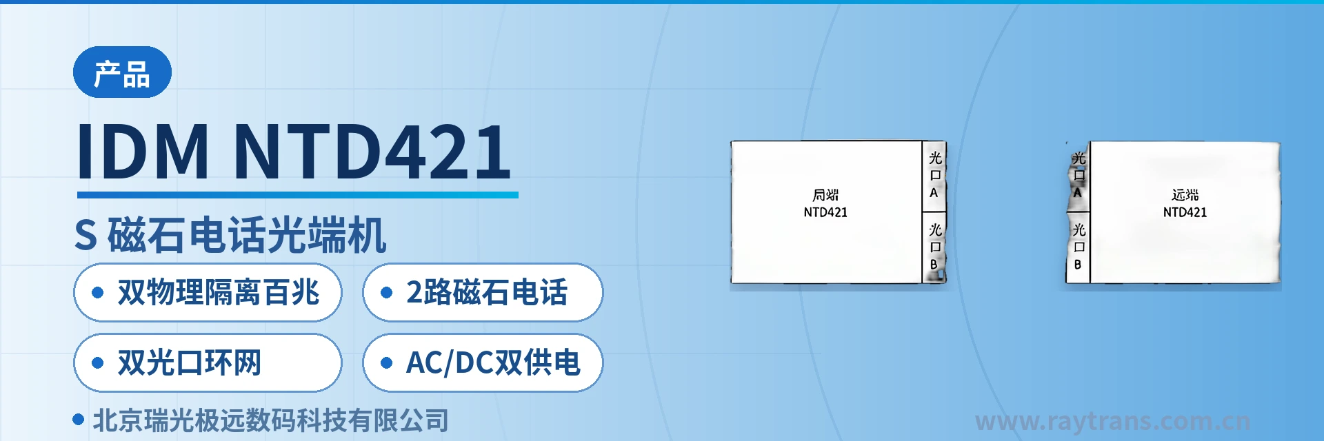
IDM NTD421 Magneto Telephone Optical Multiplexer
2 magneto voice channels, dual physically isolated Fast Ethernet, 3 ports with VLAN partitioning, dual optical port ring network DIP switch
Provides 2 telephone channels plus 2 groups of physically isolated Fast Ethernet ports, where ports 1, 2, 3 and the fourth channel are physically isolated, with 220V power supply. Dual physically isolated wire-speed 100M Ethernet channels; the three shared 100M Ethernet ports can also be partitioned by VLAN isolation. Voice channel interfaces can be FXO central office automatic telephone, FXS remote automatic telephone, or MAG magneto telephone, and 2 RS485 interfaces are provided. Supports chain network and ring network applications with dual optical port cascading. The 8-bit DIP switch on the panel is used to set the site address in a chain network. Provides a standard SNMP network management interface.
IDM NTD421 (CS) 2-channel magneto telephone optical multiplexer is an optical-electrical integrated transmission device developed by Beijing Raytrans Digital Technology Co., Ltd. (Raytrans). It aggregates magneto voice channels, physically isolated Fast Ethernet, and serial port data into a single 250M optical fiber transmission link, and is a multi-service optical multiplexer product showcase for private network scenarios. The device uses an FC single-mode optical interface, comes standard with a 20 km transmission distance, and provides 2 voice channels, 4 RJ-45 ports, and 2 RS485 interfaces. The line side supports dual optical port cascading, enabling point-to-point, chain, and ring network topologies.
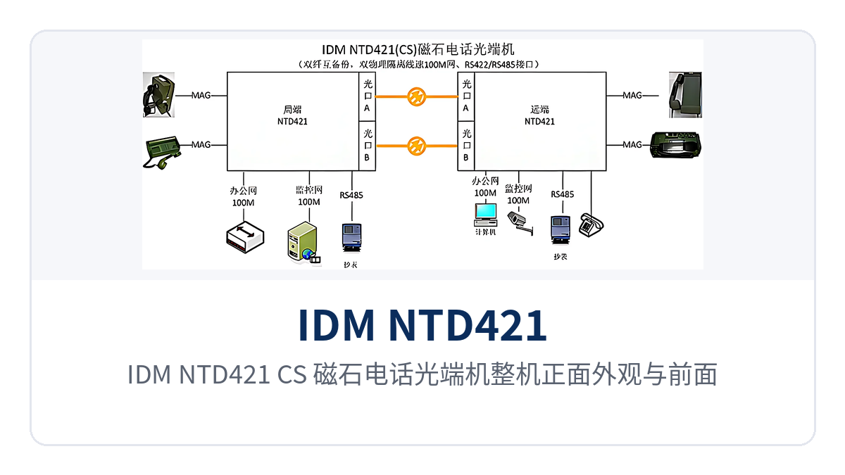
Figure 1: Front appearance and front panel indicator LED layout of the IDM NTD421 (CS) magneto telephone optical multiplexer
Key specifications at a glance: 250M optical interface · FC single-mode 20 km · 2 magneto telephone channels · dual physically isolated Fast Ethernet · 3 shared ports with VLAN partitioning · 2 RS485 interfaces · dual optical port ring network · AC/DC dual power supply
Used in pairs, the devices form a complete service link: one end connects to magneto telephones, dispatch consoles, cameras, and service networks at the site side, while the other end restores them in the equipment room or dispatch center. Only one optical fiber is needed in between, so copper cables do not have to be laid separately for voice and data, and the existing wiring of telephones and dispatch consoles does not need to be changed. As a mature model from an optical multiplexer manufacturer, this telephone optical multiplexer can carry mixed voice and data services, and is also suitable for access layer transmission in government private network optical fiber communication solutions and military emergency communications vehicle solutions.
By topology, two devices connected back-to-back form a point-to-point application; multiple devices cascaded end-to-end through their two optical ports form a chain network, with the site address set by the 8-bit DIP switch on the panel; closing the two ends of the chain into a ring forms a ring network, and when any optical cable segment is interrupted, services can be rerouted in the other direction. All three topologies share the same optical multiplexer model, and on site you only need to choose according to the number of sites and the optical cable routes; in a network where gigabit network optical multiplexers carry the backbone bandwidth, this multi-service optical multiplexer can be flexibly deployed as a leaf service aggregation node.
What kind of device is the 2-channel magneto telephone optical multiplexer?
The IDM NTD421 (CS) 2-channel magneto telephone optical multiplexer integrates voice channel access, Ethernet access, and optical transmission into a single desktop type enclosure. The optical interface is an FC single-mode interface, with a receive/transmit rate of 250M/250M, receive/transmit wavelengths of 1310nm/1550nm, a transmit optical power of -12 to -6 dBm, and a receiver sensitivity better than -18 dBm.
The user side provides 2 voice channels, 2 physically isolated Fast Ethernet channels, and 2 RS485 interfaces. The unit supports both AC 220 V and DC -48 V power supply, and the site selects one of them according to the existing power conditions, while the other end is configured as a paired configuration of the same model.
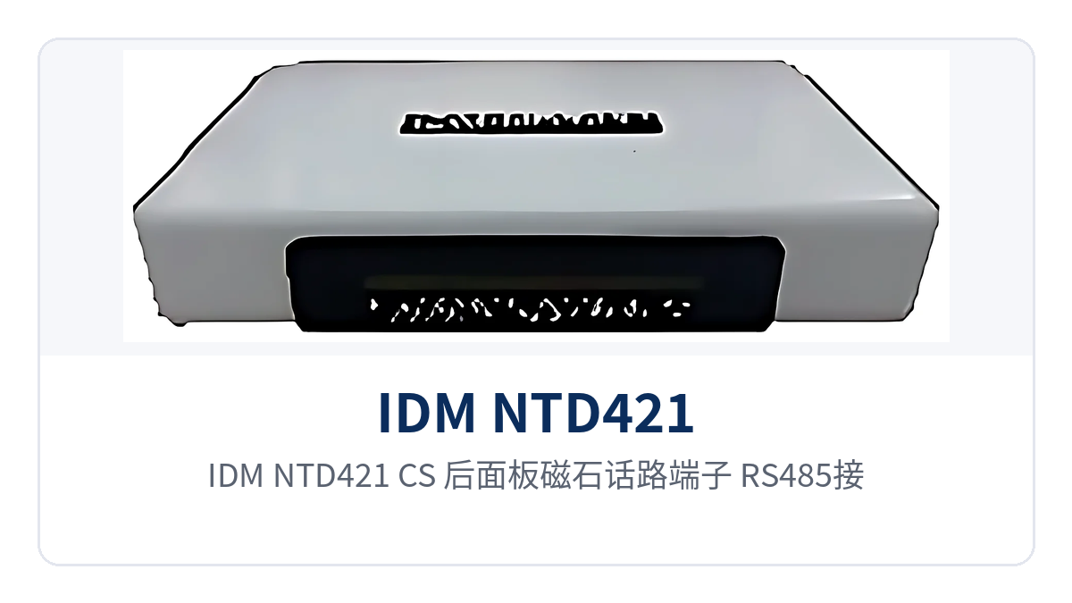
Figure 2: Rear panel layout of magneto voice terminals, RS485 interfaces, 4 RJ-45 ports, and dual optical ports on the IDM NTD421 (CS)
Magneto telephones complete calls by sending ringing current from a hand-cranked generator, while the conversation itself remains analog voice in the 300 Hz to 3400 Hz range. The device compresses the voice channel into a 64 Kbps digital signal using A-law in ITU G.711, occupies a fixed time slot, and sends it over the optical fiber, transmitting it in parallel with Ethernet services in the same optical channel. The voice channel impedance is a three-element complex impedance of 200 Ω + 560 Ω//0.1 μF, with a loop current of 20 mA per channel, allowing direct connection to magneto telephones and exchange side interfaces.
Voice channel interfaces are selected according to the existing equipment on site: FXO is the central office automatic telephone interface, used to connect to the subscriber side of a switch; FXS is the remote automatic telephone interface, used to connect directly to automatic telephones; MAG is the magneto telephone interface, connecting to hand-cranked magneto telephones and magneto switching equipment. The two voice channels on the same device can be configured as different formats according to the actual site configuration, so magneto voice channels no longer require a separate transmission device. As a professional optical multiplexer manufacturer, Raytrans offers a variety of voice channel formats and interface combinations in this product series, making it easy for users to select flexibly according to site services.
Features and Performance at a Glance
The device is designed around five categories of capabilities: voice channel access, isolated Ethernet, serial port data, redundant networking, and remote network management. Each function and its corresponding interface are listed in the table below for item-by-item comparison with the on-site service list. The table also specifies the configuration method and applicable conditions for each capability, so you only need to confirm row by row when checking service types.
| Function | Description |
|---|---|
| 250M optical interface transmission | Provides an FC single-mode optical interface, with a receive/transmit rate of 250M/250M, receive/transmit wavelengths of 1310nm/1550nm, and a standard transmission distance of 20 km |
| 2 magneto/FXO/FXS voice channels | The 2 voice channels can be configured per site as MAG magneto telephone, FXO central office automatic telephone, or FXS remote automatic telephone interfaces, with an audio range of 300 Hz to 3400 Hz |
| Dual physically isolated Fast Ethernet channels | The 4 RJ-45 ports are configured as 2 groups of physically isolated channels; the two groups do not share forwarding resources, and service data is carried on separate channels |
| 3 shared ports with VLAN partitioning | Ports 1, 2, and 3 share one group of wire-speed 100M channels, within which VLANs can be partitioned to isolate internal services; port 4 is an independent physically isolated channel |
| 2 RS485 interfaces | Provides 2 half-duplex RS485 interfaces, which can be changed to 1 full-duplex RS422 interface, for connecting serial port terminals such as metering and measurement & control devices |
| Chain/ring network DIP addressing | The 8-bit DIP switch on the panel sets the site address in the chain network, and dual optical port cascading forms point-to-point, chain, and ring topologies |
| SNMP network management | Provides a standard SNMP network management interface, allowing remote viewing of device and optical link status at the network management center and reducing on-site inspection |
| Ethernet auto-negotiation | Complies with the IEEE 802.3 standard and supports 10M/100M/1000M rate auto-negotiation and full/half duplex auto-negotiation |
Interfaces and Technical Specifications
The following specifications cover optical interfaces, Ethernet interfaces, voice channel interfaces, serial ports, power supply, and environmental conditions. The values are based on the IDM NTD421 (CS) product documentation and are intended for networking design and equipment selection calculations. During selection, first determine the interface configuration according to the site service volume, then use the optical power parameters to calculate the link budget.
| Item | Parameter/Specification | Description/Applicable Conditions |
|---|---|---|
| Optical interface type | FC | Single-mode optical interface, with optical module supplied |
| Number of optical ports | 2 × 250M optical transmission interfaces | Supports point-to-point and dual optical port cascading to form chain and ring networks |
| Fiber mode | Single-mode (multi-mode optional) | Selected according to line conditions and distance |
| Receive/transmit rate | 250M/250M | Shared by voice, Ethernet, and serial port services |
| Receive/transmit wavelength | 1310nm/1550nm | Modules at both ends are used in paired configuration |
| Transmit optical power | -12 to -6 dBm | Subject to the factory value of the selected optical module |
| Receiver sensitivity | Better than -18 dBm | Lower limit of received optical power at the end of the link |
| Transmission distance | 20 km, long-distance optical module optional | Longer distances are determined by the optical module and link budget |
| Ethernet interface | RJ-45, 4 ports | Ports 1, 2, and 3 share Fast Ethernet channels; port 4 is independently isolated |
| Ethernet rate | 10M/100M/1000M auto-negotiation | Interface auto-negotiation; service bandwidth is constrained by the 250M optical link capacity |
| Ethernet protocol | Supports IEEE 802.3 | Full/half duplex/adaptive |
| VLAN partitioning | VLANs can be partitioned on the 3 Ethernet ports sharing 100M | Used for service isolation within the shared channel |
| Voice channel interface | 2 channels, MAG/FXO/FXS selectable | Determined by whether the opposite end is a magneto telephone, automatic telephone, or exchange side |
| Audio range | 300 Hz to 3400 Hz | Standard telephone voice bandwidth |
| Voice compression | A-law in ITU G.711 | 64 Kbps digital voice per channel |
| Voice channel impedance | Three-element complex impedance 200 Ω + 560 Ω//0.1 μF | Matches common magneto telephones and exchange side interfaces |
| Loop current | 20 mA/channel | Feeding capability of each voice channel |
| Serial port interface | 2 half-duplex RS485, or 1 full-duplex RS422 | Used for serial port data access such as metering and measurement & control |
| Site address setting | 8-bit DIP switch on the panel | Sets the local site address during chain network networking |
| Network management interface | Standard SNMP | Connects to the existing NMS platform for unified monitoring |
| Power supply mode | AC 220 V/DC -48 V | Selected according to site power conditions, achieving AC/DC dual power supply |
| Overall power consumption | ≤90 W | Unit value including optical modules |
| Operating temperature | -10℃ to +50℃ | Installed in equipment rooms, cabinets, and outdoor enclosures |
| Relative humidity | 0 to 95% (non-condensing) | For use in non-condensing environments |
| Dimensions | Subject to the documentation supplied with the product | Verify against cabinet space before installation |
How are services allocated across the dual physically isolated Fast Ethernet ports?
The allocation principle is to let data of different security levels travel over independent channels, and to keep voice and data from contending within their respective channels. On site, group the Ethernet ports according to service assignment, carrying external communication and internal production data separately, and record the grouping results in the site wiring table to avoid connecting services from different security domains to the same group of ports during installation.
- Isolated channel 1: Port 4 is an independent physically isolated wire-speed 100M channel, suitable for services such as dispatch automation and protection information that need to be strictly separated from external networks.
- Shared channel 2: Ports 1, 2, and 3 share one group of wire-speed 100M channels, suitable for internal services such as office networks and video surveillance.
- In-channel isolation: VLANs can be partitioned on the shared channel to add a layer of logical isolation for different services on the same group of ports.
- Voice and serial ports: The 2 voice channels connect to magneto telephones or dispatch consoles, and the 2 RS485 interfaces connect to metering and measurement & control terminals, carried on separate channels from Ethernet services.
The channel grouping of the dual physically isolated Fast Ethernet optical multiplexer is performed inside the device and does not depend on the VLAN configuration of upper-layer switches, so the channel partitioning remains effective when the upper-level device loses power or changes configuration. For sites such as electric power and rail transit that have both dispatch voice and automation data, this allocation method reduces the number of devices and the number of cables. Raytrans's multi-service optical multiplexer and gigabit network optical multiplexer product lines also support service-based channel carrying. In government private network optical fiber communication solutions and military emergency communications vehicle solutions, the various optical multiplexer devices in the product showcase can be flexibly combined according to site service types.
How are chain and ring network magneto telephone optical multiplexers networked?
Chain and ring network magneto telephone optical multiplexers rely on the two 250M optical ports built into the device to cascade into a network, without additional switching or aggregation equipment in between. Each device uses its two optical ports to connect to the previous station and the next station respectively, stringing the sites into a chain; connecting the head and tail of the chain back together forms a ring network. The site address is set via the 8-bit DIP switch on the panel, and addresses within the same chain network must not be duplicated. As a professional optical multiplexer manufacturer, Raytrans clearly indicates the dual optical port cascading capability of this product series in its product showcase, making it easy for engineering personnel to quickly verify networking parameters.
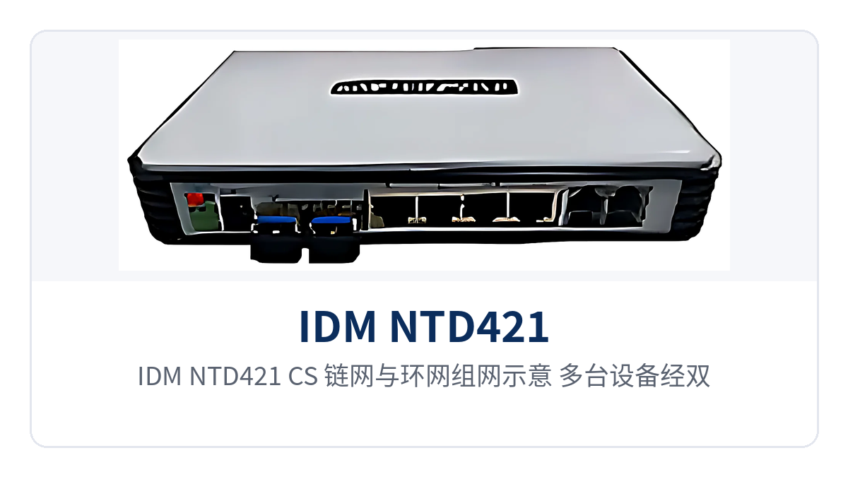
Figure 3: Chain and ring network diagram of the IDM NTD421 (CS), with multiple devices cascaded end-to-end through dual optical ports
The value of a ring network lies in its rerouting capability during optical cable failures: when a segment of optical cable is interrupted, services reach the destination site along the other direction of the ring, without changing the service interfaces or terminal configurations at either end. In engineering practice, optical cables between adjacent sites should be routed along different paths so that the rerouting value of the ring network can truly be realized; multiple breakpoints on a single route will still affect services.
The construction requirements for dual optical port ring network cascading focus on two points: first, the receive/transmit wavelengths of the optical modules at adjacent sites must be configured in pairs; second, the DIP switch site addresses of each station must be uniformly numbered and written into the construction drawings before work begins. Once these two items are verified before commissioning, subsequent capacity expansion only requires adding stations to the chain and changing DIP switch settings, without modifying the service configuration of stations already in operation.
What statuses can the SNMP network management of the magneto telephone optical multiplexer monitor?
The conventional items that can be viewed include device presence, optical port receive/transmit status, Ethernet and voice channel interface status, and power supply alarms. The specific alarm entries and MIB definitions that can be read are subject to the network management documentation provided by the manufacturer. After these statuses are connected to an existing NMS platform, inspection can change from periodic on-site visits to remote viewing, and fault diagnosis at unattended sites also becomes faster.
For chain networks and ring networks, the value of network management lies in positioning: when a site on the chain loses contact, the network management system can indicate between which sites the breakpoint lies, and maintenance personnel can take optical modules and patch cords and go straight to that section of optical cable. This positioning method saves a great deal of travel compared with site-by-site inspection, and the improvement in handling efficiency is even more pronounced at mountainous areas and sites along the line.
Can a 20Km single-mode magneto telephone optical multiplexer transmit farther?
20Km is the standard transmission distance; the actual achievable distance is determined jointly by the optical module and the link loss. When a longer distance is required, simply replace the module with a long-distance optical module; the device itself and the service interfaces remain unchanged. As a 20Km single-mode magneto telephone optical multiplexer, the two ends of the link are configured with modules in pairs at 1310nm and 1550nm wavelengths, and the per-kilometer attenuation of the single-mode fiber is taken according to the selected wavelength.
For the calculation, use the transmit optical power of -12~-6dBm and the receiver sensitivity better than -18dBm for the link budget, then include optical fiber attenuation, splice points, mating connectors, and optical cable margin. In addition to the calculation result, a margin of several dB is generally reserved; the specific value is determined according to the project design requirements. When the margin is insufficient, first replace with a long-distance module rather than shortening the inter-station distance.
How is the link budget calculated for a 20Km single-mode magneto telephone optical multiplexer?
The link budget is calculated item by item in four steps, to avoid ordering solely on the basis of the nominal 20Km. The value of each step is taken from the selected optical module and the actual line measurement data; missing any one item may overestimate the usable distance, and insufficient received optical power after commissioning then requires rework and module replacement at a higher cost.
- Transmit optical power: take the factory value of the selected optical module, in the range of -12~-6dBm.
- Receiver sensitivity: use better than -18dBm as the lower limit of received optical power at the end of the link.
- Line loss: take the per-kilometer attenuation value according to the wavelength and optical fiber type, multiply by the optical cable length, then add the splice point and connector losses.
- Margin and recalculation: reserve a margin of several dB according to project requirements, subtract all losses from the transmit optical power, and the result must be higher than the receiver sensitivity.
Typical Application Scenarios
What the three types of scenarios have in common is distributed sites, voice and data that must arrive at the same time, and on-site conditions that often do not allow separate cabling for each type of service. The same multi-service optical multiplexer carries magneto voice channels, isolated network ports, and serial port data over one optical fiber, so the number of site-side devices and cables decreases and the O&M interface is also consolidated in one place.
Electric Power Distribution Network and Substation Communication
Dispatch telephone between substations and distribution network switching stations mostly uses magneto telephones, which do not depend on external power or switching equipment and can still communicate during a power outage. The MAG interfaces of the IDM NTD421 (CS) 2-channel magneto telephone optical multiplexer connect directly to magneto telephones and deliver voice to the dispatch center, so there is no need to set up a separate audio transmission device for the magneto voice channels.
The same site also needs to carry protection information, metering data, video surveillance, and other services, and the two types of data have different security levels. The dual physically isolated Fast Ethernet ports place dispatch automation data on an independent channel and office and video services on a shared channel that can be divided into VLANs, so one optical fiber carries voice and data simultaneously without mutual interference. Raytrans adopts the same isolation approach in its government private network optical fiber communication solution, carrying services of different security levels on separate channels.
Communications Along Rail Transit Lines
Sites along the rail transit line are distributed in a belt, with inter-station distances ranging from several hundred meters to several kilometers, and optical cables are laid along the line. The dual optical ports of the device are cascaded to form a chain network; the voice channels, platform broadcast control data, and video services of each station are accessed site by site and aggregated at the central station, so there is no need to pull a separate fiber core from each station to the center.
The temperature difference and dust along the line are a real challenge to the equipment; the operating temperature range of -10℃+50℃ and the 095% non-condensing humidity condition cover the common operating conditions of trackside cabinets and in-station equipment rooms. The ring network topology adds another layer of assurance: when the section optical cable is cut by construction, services reach the center along the other direction of the ring, and dispatch telephone is not interrupted.
Military and Armed Police Private Network Communication
Private network communication emphasizes self-contained systems and survivability; links must not depend on the public network, and the topology must also be adjustable with the mission. The device supports three topologies: point-to-point, chain network, and ring network. Dual optical port cascading and front-panel DIP switch address setting allow temporary networking over field optical cable to communicate once powered on, and changing a site address does not require reconfiguring software. In the military emergency communications vehicle solution, this rapid networking capability is particularly critical; voice and data channels can be established within a short time after the vehicle arrives.
Magneto voice channels are likewise a fallback means in such scenarios: the telephone has its own hand-cranked generator and local ringing current, and only digitized voice is transmitted over the optical fiber link, without depending on external switch power supply. The 2-channel RS485 interfaces can also connect serial port terminals such as weather and radar equipment, bringing voice and data into the same field optical cable.


