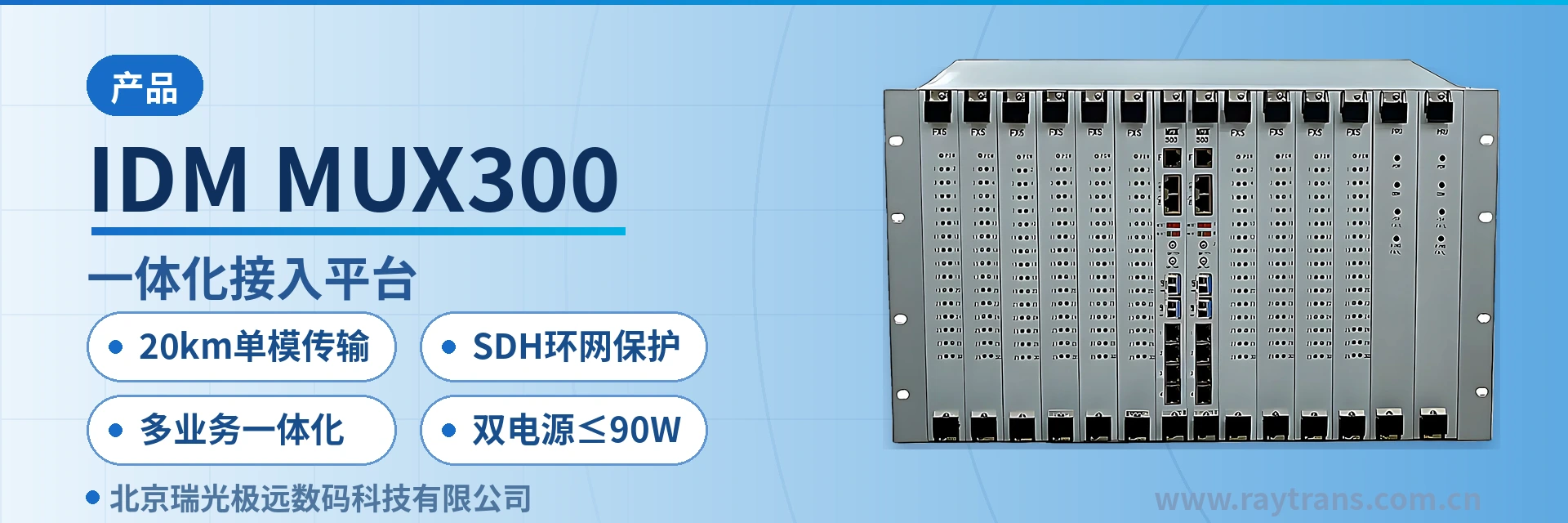
IDM MUX300 Integrated Access Platform
SDH and PCM in one chassis, 252×252 VC-12 cross-connect, saves one standalone
The SDH equipment is a new-generation optical-electrical integrated transmission device developed by our company based on MSTP and PCM technologies. It integrates MSTP transmission and PCM multi-service access functions, meeting users' requirements for optical fiber transmission and access of multiple broadband and narrowband services, and uses SDH ring network protection to provide more reliable communication protection. The IDM MUX300 optical-electrical integrated equipment can directly connect to remote terminals such as telephones, computers, and cameras, adapting to various networking topologies.
The IDM MUX300 multi-service optical-electrical integrated transmission equipment is a new-generation optical-electrical integrated transmission device developed by Beijing Ruiguang Jiyuan Digital Technology Co., Ltd. (Raytrans) based on MSTP and PCM technologies. It combines SDH transmission and PCM multi-service access into a single 19-inch 6U chassis, providing a compact integrated platform for the product showcase.
The equipment provides 2-channel SFP STM-1 optical access and 252×252 VC-12 level non-blocking cross-connection, and can directly connect to remote terminals such as telephones, computers, and cameras, adapting to various networking topologies including ring networks, chain networks, and star networks. As a professional SDH equipment manufacturer, Raytrans deeply integrates the optical transmission capability of SDH equipment with multi-service access, enabling the optical transmission equipment to directly connect to various remote terminals.
For electric power, rail transit, and military private networks, a single device simultaneously carries E1 protection channels, Ethernet, dispatch telephone, and telecontrol data, so the station does not need to deploy separate transmission equipment for each service type. Single-fiber 20 km transmission combined with SDH ring network protection allows services to be delivered along the other direction of the ring after a single point of failure on the link, and telephone and data terminals do not need to re-establish connections. With its accumulated MSTP and SDH expertise, Raytrans provides reliable optical multiplexer manufacturer-level support for government private network optical fiber communication solutions and military emergency communications vehicle solutions.
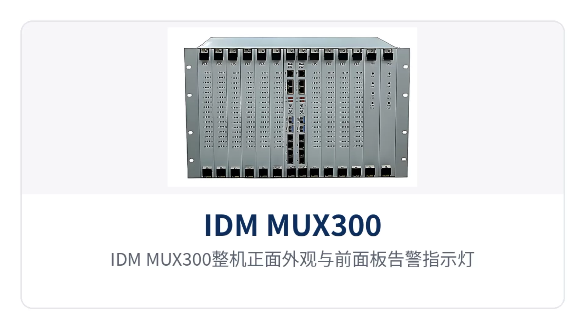
Figure 1: Front appearance of the IDM MUX300 unit and front panel alarm indicator LEDs
Key specifications at a glance: 20 km single-mode transmission · SDH ring network protection · multi-service integration · dual power supply ≤90 W · 2-channel SFP STM-1 · 252×252 VC-12 cross-connection · 10 service card slots
What does 252×252 VC-12 cross-connection solve for private networks
VC-12 is the channel granularity carrying 2.048 Mbps in the SDH multiplexing hierarchy. A 252×252 VC-12 level cross-connection means the equipment can arbitrarily assign time slots between 252 VC-12 inputs and 252 VC-12 outputs, supporting unidirectional, bidirectional, and broadcast services.
Cross-connect capability determines how many E1 channels and Ethernet channels an SDH device can schedule, and also determines whether additional cross-connect equipment is needed during service capacity expansion. The transmission rate and line coding of the E1 interface follow the 2.048 Mbps and HDB3 specifications of ITU-T G.703, and no additional conversion unit is required when interconnecting with existing PDH equipment.
The IDM MUX300 multi-service optical-electrical integrated transmission equipment adopts a 19-inch standard 6U chassis and card-based design, providing 10 6U user card slots, with service cards configured according to the on-site service list. The 2 SFP optical ports operate at 155.52 Mbps and can form ring networks, chain networks, and star networks; the 4 groups of EoS Ethernet are physically isolated from each other, each group has a configurable bandwidth of N×VC12 (N=1~50), and works with 8FE cards to expand the number of Ethernet interfaces.
Which service interfaces does the IDM MUX300 multi-service optical-electrical integrated transmission equipment support
The equipment integrates PCM integrated service access and SDH optical transmission in the same chassis. Voice, data, and Ethernet services are accessed by card, and capacity expansion only requires adding service cards. The following table lists each capability and its corresponding conditions by function, making it easy for projects to check the configuration item by item against the service list.
| Function | Description |
|---|---|
| SDH optical transmission | 2-channel SFP STM-1 optical access, receive/transmit rate 155.52 Mbps, can form ring, chain, star, and other topologies |
| VC-12 cross-connection | 252×252 VC-12 level non-blocking cross-connection, supporting unidirectional, bidirectional, and broadcast services |
| EoS Ethernet | 4 groups of physically isolated EoS Ethernet, each group with a configurable bandwidth of N×VC12 (N=1~50), each group reserving 1 group of expansion Ethernet ports, working with 8FE cards to expand the number of interfaces |
| PCM voice access | Provides FXO/FXS interfaces, audio range 300 Hz~3400 Hz, compression compliant with ITU G.711 A-law, loop current 20 mA/channel |
| 2/4-wire audio | Provides E&M 2/4-wire interfaces and magneto interfaces, balanced 600 Ω impedance, return loss no less than 18 dB |
| 64K data access | Provides codirectional 64K interface (G.703 standard, 64 Kbps, balanced 120 Ω), V.24 interface, and V.35 interface |
| Synchronization timing | Supports SETS synchronous equipment timing source, can track the optical line timing source or external synchronization input/output (2.048 Mbit/s or 2.048 MHz), and automatically switches the timing source based on failure or SSM |
| Network management and cascading | Provides F (10M/100M) network management interface and equipment network management cascading interface, implements configuration, alarm, performance, maintenance, and security functions through the NetGuard management system, and supports SNMP |
| Power supply mode | AC220V/DC-48V two formats, optional DC+DC, AC+AC, AC+DC dual backup power supply, overall power consumption ≤90 W |
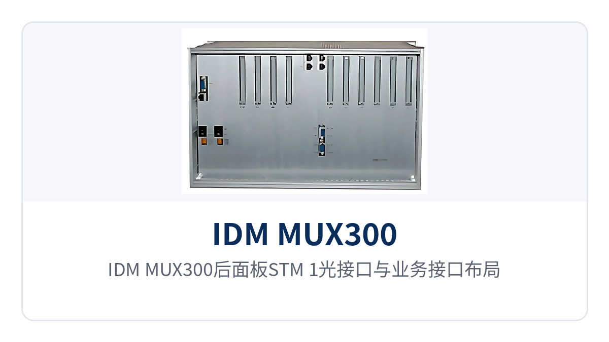
Figure 2: Layout of STM-1 optical interfaces and service interfaces on the IDM MUX300 rear panel
Overview of optical port, E1, and various service interface parameters
The following table summarizes the parameters of optical interfaces, E1, Ethernet, voice, and data interfaces. The values are taken from the product technical documentation and can be checked item by item during engineering design and incoming acceptance. Items not listed in the table are subject to the SDH equipment manufacturer's technical documentation and commercial confirmation, and parameters of similar equipment shall not be applied.
| Item | Parameter/Specification | Description/Applicable Conditions |
|---|---|---|
| Optical interface type | SFP, single-mode (multi-mode optional) | Optical modules selected by distance and wavelength |
| Receive/transmit rate | 155.52 Mbps/155.52 Mbps | STM-1 level, 2 optical ports can form a ring network |
| Receive/transmit wavelength | 1310 nm/1550 nm | Modules at both ends paired by wavelength |
| Transmit optical power | -12~-6 dBm | Used to calculate the optical link budget |
| Receiver sensitivity | Better than -32 dBm | Covers splicing and aging margin |
| Transmission distance | 20 Km | Long-distance optical modules can be optionally installed for longer transmission |
| E1 bit rate and line coding | 2.048 Mbps, HDB3 | Frame structure PCM30/32, channel-associated signaling |
| E1 standard and impedance | Supports ITU-T G.703, 75 Ω/120 Ω | Select impedance according to the opposite end's interface |
| Ethernet interface | RJ-45, transmission rate N×VC12 (N≤50) | Supports IEEE802.3, full/half duplex/adaptive |
| FXO/FXS impedance | Three-element complex impedance 200 Ω+560 Ω//0.1 μF | Audio range 300 Hz~3400 Hz, ITU G.711 A-law |
| Codirectional 64K interface | G.703 standard, 64 Kbps, balanced 120 Ω | Fully compliant with ITU-T G.703 recommendation |
| E&M 2/4-wire and magneto interfaces | Balanced 600 Ω, return loss no less than 18 dB | Audio range 300 Hz~3400 Hz, ITU G.711 A-law |
| V.24 interface | Asynchronous ≤9600 bps; synchronous 64 Kbps | Electrical characteristics compliant with CCITT V.28 protocol |
| V.35 interface | n×64 Kbps (n=0~31), RJ-45 | Compliant with ITU-T V.35 recommendation, terminal interface compliant with ISO2593 |
| Power supply and power consumption | AC220V/DC-48V, overall power consumption ≤90 W | Optional dual backup power supply |
| Operating environment | -10℃ |
Equipment room and substation communications room environment |
| Dimensions | 482×266×270 (mm) | 19-inch 6U rack installation |
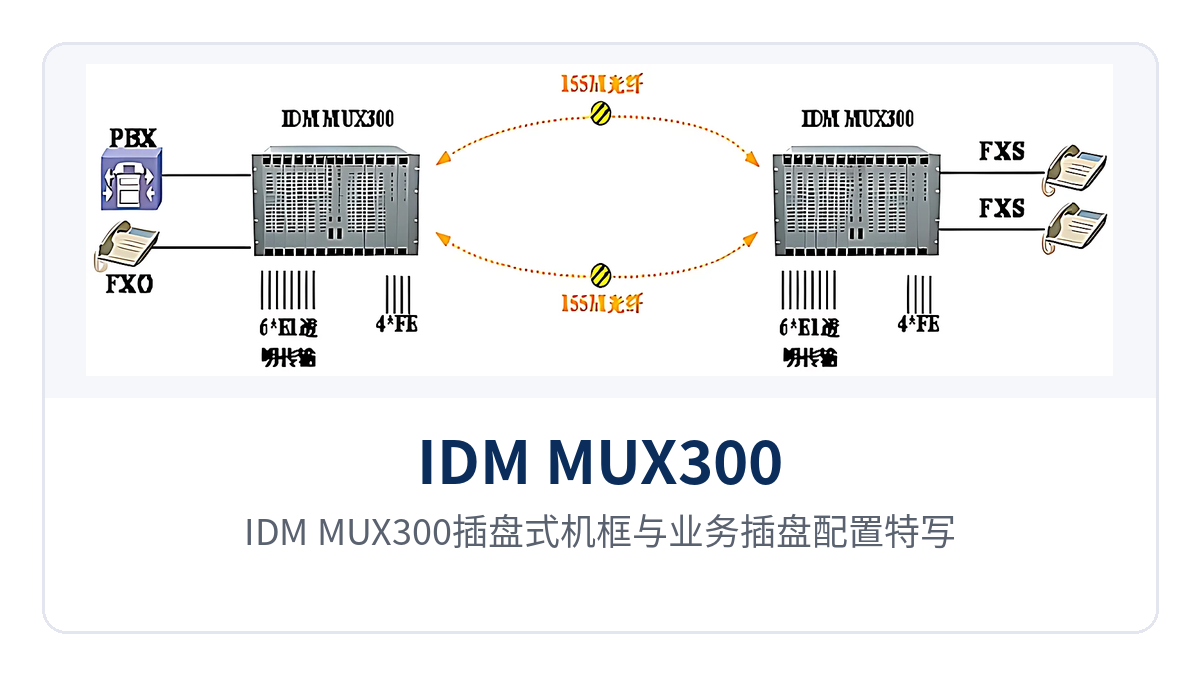
Figure 3: Close-up of the IDM MUX300 card-based chassis and service card configuration
How SDH ring network protection and dual power supply ensure services uninterrupted
SDH ring network protection relies on simultaneous transmission and reception in two optical directions and reserved protection time slots at the channel layer. When any segment of the link is interrupted, services are automatically switched to the other side of the ring. The switchover is completed at the transmission layer, and upper-layer telephone and data services do not need to redial or reconnect. This is how SDH ring network protection provides reliable communication for private networks.
The two SFP optical ports of the IDM MUX300 are designed for ring formation. Multiple stations closed along two directions form a ring network; when stations are distributed linearly, they are networked as a chain network; when stations are concentrated at a central station, they are networked as a star network. The E1 and Ethernet channels in the service cards occupy their own VC-12 time slots on the ring network, and maintenance on one link does not affect services carried by other time slots.
The power supply side supports AC220V and DC-48V formats, with optional DC+DC, AC+AC, and AC+DC dual backup power supply, and overall power consumption ≤90 W. Both the substation DC distribution panel and the equipment room AC mains power can be connected directly. Unattended sites are configured according to on-site power supply conditions, and no additional power conversion unit is required for the equipment.
The optical link budget is calculated based on transmit optical power of -12~-6 dBm and receiver sensitivity better than -32 dBm. The margin reserved for single-fiber 20 km transmission covers on-site splicing and aging loss. Stations beyond 20 km can optionally install long-distance optical modules, with distance and wavelength confirmed by pairing the modules at both ends.
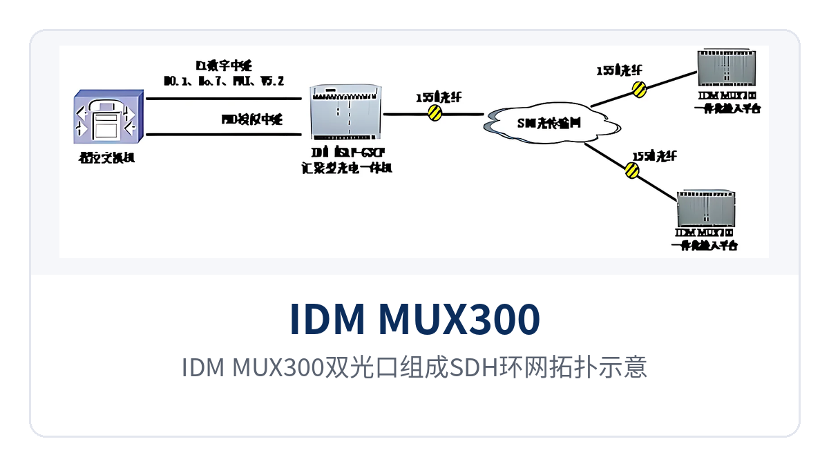
Figure 4: Schematic of an SDH ring network topology formed by the IDM MUX300 dual optical ports
Typical application scenarios
Electric power private network: one device carries E1 protection channels and dispatch telephone in substation communication upgrades
Between a substation and a dispatch center, dispatch telephone, telecontrol data, video surveillance, and office Ethernet usually coexist. There are many service types, but the service volume of a single station is not large. The IDM MUX300 combines E1 protection channels, EoS Ethernet, FXO/FXS dispatch telephone, and 64K telecontrol data into the same SDH device, leaving only one 6U rack position in the station cabinet. This is the integrated station configuration commonly seen in electric power private network communication upgrades, and also a typical multi-service access solution in the SDH product showcase.
During implementation, cards are configured according to the on-site service list: relay protection and safety control channels use E1 interfaces, monitoring and office use physically isolated EoS Ethernet, dispatch telephone uses FXO/FXS cards, and telecontrol data uses 64K or V.24 interfaces. Ring network protection covers a single point of failure on the optical cable, and dual power supply covers AC/DC switching within the station. Redundancy at both layers does not depend on upper-layer equipment coordination.
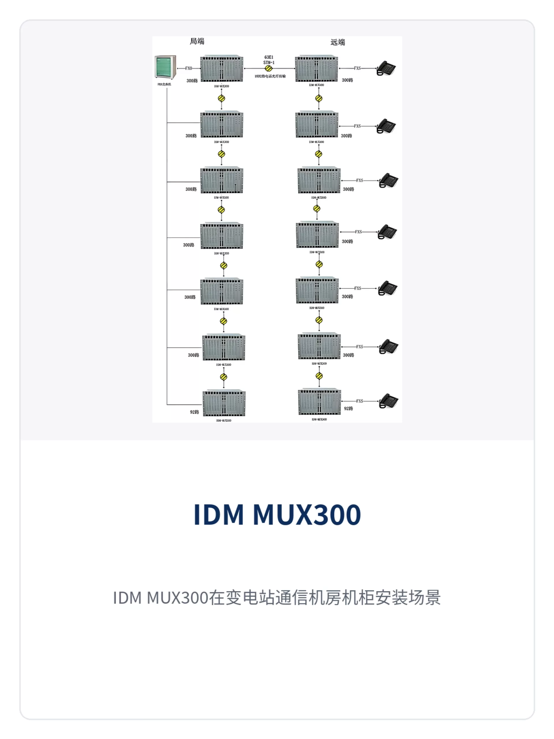
Figure 5: IDM MUX300 installed in a cabinet in a substation communications equipment room
Rail transit communication: 20 km single-fiber coverage and ring network protection between sections
Stations along a rail line are far apart, and power supply access and maintenance conditions in sections are limited. Optical transmission equipment needs to cover long sections with fewer repeater conditions. Single-fiber 20 km transmission eliminates the need to add repeaters in the sections between adjacent stations, and ring network protection limits the impact of accidental interruption of section optical cables to the switchover time, keeping train dispatch telephone and section services connected.
Official telephone, section telephone, broadcast audio, and monitoring data in the station can be connected to FXO/FXS, E&M 2/4-wire, and EoS Ethernet interfaces respectively, with the same device providing independent VC-12 channels for each service type. During section maintenance or optical cable cutover, services are transmitted along the other direction of the ring, and the dispatch center does not need to reconfigure each station.
Military and government private networks: DC-48V dual power supply adapts to unattended equipment rooms
Field sites and unattended equipment rooms commonly use -48V DC power supply, while some sites have only AC mains power, so power supply conditions are not uniform. The IDM MUX300 supports both AC220V and DC-48V formats and can be equipped with dual backup power supplies. Its overall power consumption is ≤90W, and the low power consumption feature allows sites to run longer on storage battery backup. Such configurations are common in military emergency communications vehicle solutions and government private network optical fiber communication solutions.
Multi-service integrated access lets one device carry voice, data and Ethernet services at the same time: command telephone traffic runs over FXO/FXS, service data over V.24 or V.35, and image and office data over EoS Ethernet. The device supports SETS synchronous timing and automatically switches the timing source according to failure or SSM, so clock synchronization is maintained even in multi-level networks formed by concatenating chain networks and ring networks.
How to Select and Deploy: Five Items to Check
Selection starts with five items—optical ports, service cards, topology, power supply and network management—and the complete unit configuration can be finalized once each item is aligned with on-site conditions. The five items below can serve directly as a checklist for confirmation with the commercial team and the construction party, and each corresponds to something that needs maintenance after the equipment is put into operation.
- Optical ports and distance: Select SFP modules according to the distance between adjacent sites. Use standard modules within 20 km; for distances over 20 km, select long-distance optical modules and confirm the wavelength pairing at both ends.
- Service card configuration: Determine card type and quantity according to the number of E1 channels, number of telephone channels, Ethernet group count and number of data interfaces, keeping capacity expansion margin in the 10 slots.
- Networking topology: A ring network requires two optical directions to close the ring, a chain network connects sites in sequence, and a star network suits scenarios where services are concentrated at the central station.
- Power supply mode: Choose DC-48V where the equipment room has a DC distribution panel, and AC220V for AC mains power. For important sites, choose dual backup power supplies fed from different distribution circuits.
- Network management access: Reserve the F network management interface and cascading interfaces, connect to the NetGuard management system or SNMP network management, and verify alarm reporting and performance collection before the equipment is put into operation.