IDM MUX180 Optical-Electrical Integrated Transmission Equipment
17-slot mixed insertion, one chassis houses E1, Ethernet, and 170 channels of 64K, saving three devices
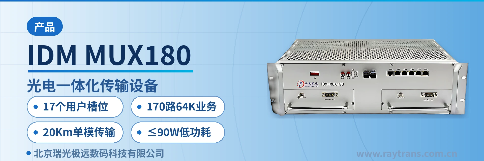
IDM MUX180 SDH equipment, 155M optical interface, 19-inch standard 3U chassis, provides 17 user slots, (24 E1 + 4×EOS FE + 170 channels of narrowband 64K services)
The IDM MUX180 17-slot mixed-insertion optical-electrical integrated transmission equipment is an SDH and PCM integrated transmission device developed by Beijing Ruiguang Jiyuan Digital Technology Co., Ltd. It consists of a 155M SDH optical transmission unit, a cross-connect unit, and 17 mixed-insertion service slots, and is used to simultaneously carry E1, Ethernet, and narrowband 64K services over a single optical fiber. It is an SDH equipment designed for the private network access layer.
Sites at the private network access layer often deploy E1 transmission, Ethernet extension, and telephone access on three separate devices, which increases cabinet space, patch panels, and power circuits accordingly. The IDM MUX180 consolidates the three service types into a single 19-inch 3U chassis, and a single unit can support mixed insertion of 24 E1 channels, 4 groups of EOS FE, and 170 narrowband 64K services. With one less layer of equipment at the access node, cabinet space, jumper count, and points of failure are reduced simultaneously, providing a compact SDH equipment selection for government private network optical fiber communication solutions and military emergency communications vehicle solutions.
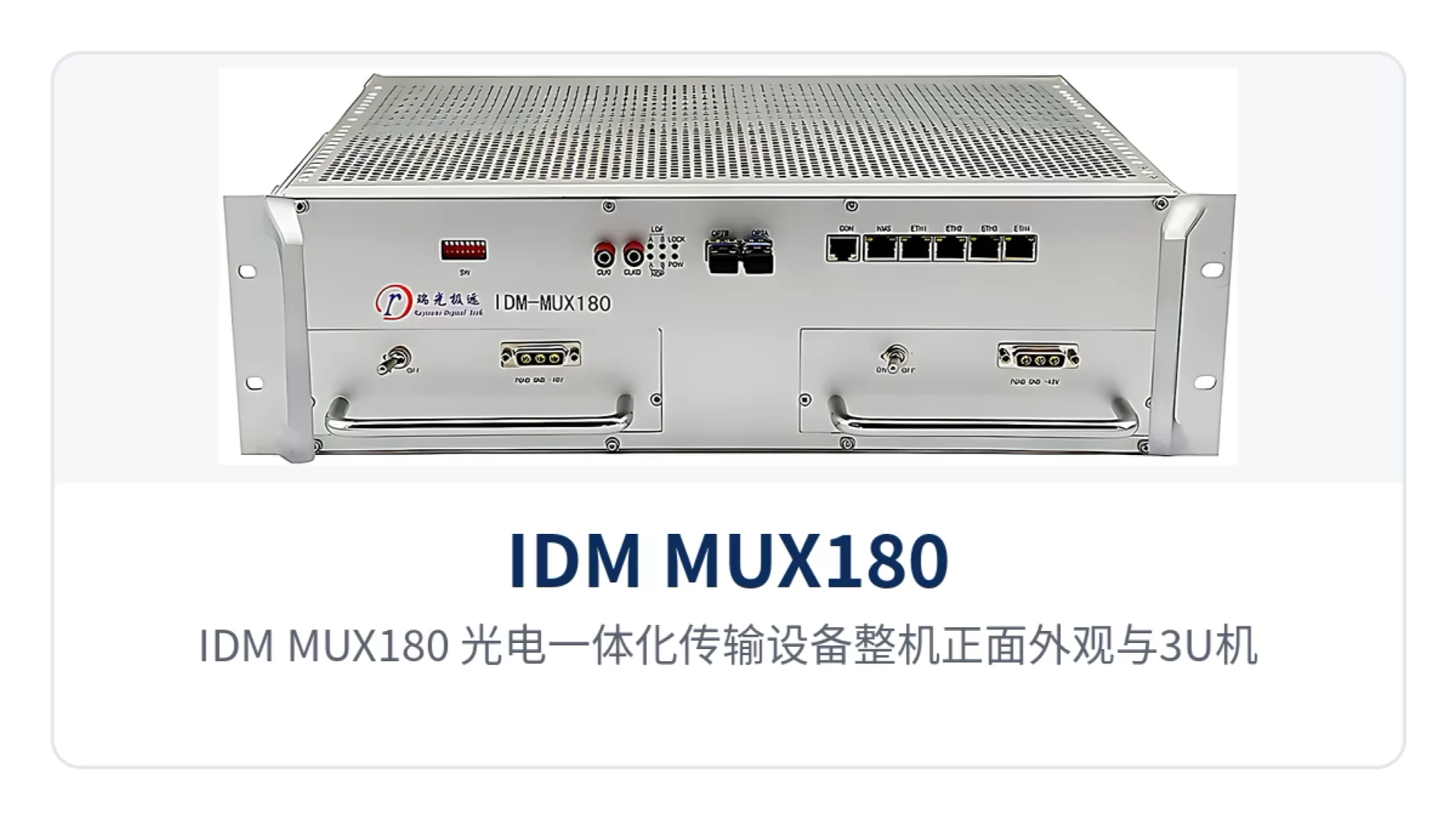
Figure 1: Front view of the IDM MUX180 optical-electrical integrated transmission equipment, with close-ups of the 3U chassis card slots and optical link alarm indicator LEDs
Key Specifications at a Glance: 17 user slots · 170 64K services · 24 E1 channels · 4 groups of EOS FE · 20 km single-mode transmission · receive/transmit rate 155.52 Mbps · receiver sensitivity better than -32 dBm · ≤90 W low power consumption · AC 220 V/DC -48 V dual power supply · 19-inch 3U
As an SDH equipment manufacturer, Raytrans has achieved unified bearing of SDH optical transmission and PCM services on the IDM MUX180. Its product showcase clearly reflects its positioning as optical transmission equipment: the unit performs single-mode 20 km transmission at an SDH rate of 155.52 Mbps, with receiver sensitivity better than -32 dBm, ≤90 W low power consumption, and support for AC 220 V/DC -48 V dual power supply, making it suitable as an SDH equipment for private network access in the Raytrans series.
What is a 17-slot mixed-insertion optical-electrical integrated transmission equipment? Three service types in one chassis
The line side is a 155.52 Mbps STM-1 optical channel, and the tributary side consists of 17 mixed-insertion service slots. After narrowband services enter the slots, they are multiplexed into E1 by 64K time slots and then allocated by the cross-connect unit to VC-12 containers on the optical line; Ethernet services occupy bandwidth in the form of N×VC12. A single STM-1 can accommodate 63 VC-12s, and E1, Ethernet, and 64K services each occupy independent containers within the same optical channel without preempting one another. As an SDH equipment designed for multi-service access, this model achieves unified bearing of SDH optical transmission, narrowband services, and Ethernet services within a single chassis.
The chassis is a 19-inch standard 3U unit with dimensions of 482×309×132 mm and a card-based design. The 17 user slots are populated card by card according to the site service point table. When fully configured, it provides 24 E1 channels, 4 groups of EOS FE, and 170 narrowband 64K services simultaneously; the service types vary with the inserted cards, while the optical ports and cross-connect unit remain unchanged. This product showcase approach intuitively demonstrates the flexibility of an SDH equipment manufacturer in the structural design of optical transmission equipment. In this series, Raytrans decouples service cards from the optical line unit, facilitating configuration on demand.
Panel indicator LEDs display the operating status of the optical path and each tributary, allowing on-duty personnel in the equipment room to read alarms directly in front of the cabinet without opening the cover to check each card. On the network management side, unified monitoring is provided through DCC, E1, N×64K, or TCP/IP channels, and alarms can be localized to a specific site by section.
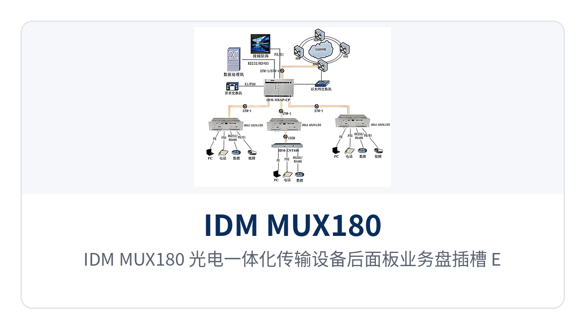
Figure 2: Rear panel layout of the IDM MUX180 optical-electrical integrated transmission equipment, showing service card slots, E1 and Ethernet interfaces, and power terminals
Core Functions: Access, Multiplexing, Cross-Connection, and Transmission Each Handle Their Own Part
The capabilities of the IDM MUX180 are distributed across four stages: access, multiplexing, cross-connection, and transmission. The table below lists each function and its role; during card configuration, verify card types and quantities against the project service point table. The table lists the maximum capabilities of the unit; the actual number of interfaces is determined by the card configuration. This SDH equipment can be used as an access layer node in both government private network optical fiber communication solutions and military emergency communications vehicle solutions, and Raytrans series products offer similar slot mixed-insertion capabilities in comparable scenarios.
| Function | Description |
|---|---|
| 17 user slots | The 3U chassis provides 17 front-insertion service card slots, allowing telephone cards, E1 cards, data cards, Ethernet cards, and audio cards to be mixed within the same chassis |
| 24 E1 access | The tributary side can provide 24 E1 channels compliant with ITU-T G.703, with selectable 75 Ω/120 Ω impedance, directly connecting to the 2M tributaries of SDH, PDH, and PCM equipment |
| 170 64K services | Narrowband slots carry 64 kbit/s services such as FXO/FXS, hotline, magneto, E&M 2/4-wire, and codirectional 64K, with up to 170 channels per fully configured unit |
| 4 groups of EOS FE | 4 groups of EOS Fast Ethernet interfaces compliant with IEEE 802.3, each with bandwidth configured as N×VC12 (N≤50) and adaptive full/half duplex |
| 155M optical transmission | SFP optical ports with receive/transmit rate of 155.52 Mbps and wavelengths of 1310 nm/1550 nm; standard single-mode transmission distance of 20 km, with long-distance optical modules available |
| Cross-connection | Provides 252×252 VC-12 level non-blocking cross-connection, supports unidirectional, bidirectional, and broadcast services, and allows any user time slot to be assigned to any line container |
| Synchronization timing | Clock source options include line clock, external clock at 2 Mbit/s or 2 MHz, and free-run, organized according to the existing network timing links |
| Alarms and network management | Panel indicator LEDs display optical path and tributary status, and SNMP network management is provided over DCC, E1, N×64K, and TCP/IP channels |
How to Verify Key Specifications: Optical Ports, E1, Ethernet, and Power Supply
The specifications are listed by group: optical interface, E1, Ethernet, voice, and power supply environment. The verification sequence is to first calculate the optical power budget, then count the E1 directions and service points, and finally confirm the power supply mode and cabinet space; the values in the table below are taken from product technical documentation, and engineering calculations are subject to on-site fiber and cabling conditions. Raytrans series SDH equipment maintains consistent specification labeling, making it easy for design institutes and integrators to reference directly during the solution phase.
Optical Interface and Transmission Distance
| Item | Parameter/Specification | Description/Applicable Conditions |
|---|---|---|
| Interface type | SFP | Pluggable optical module; single-mode is the standard configuration, with multimode optional |
| Receive/transmit rate | 155.52 Mbps/155.52 Mbps | STM-1 line rate, with identical receive and transmit rates |
| Receive/transmit wavelength | 1310 nm/1550 nm | Wavelengths at both ends must match the module model |
| Transmit optical power | -12 to -6 dBm | Available transmit-side optical power range |
| Receiver sensitivity | Better than -32 dBm | Receive threshold for weak optical links |
| Transmission distance | 20 km | Standard single-mode configuration; long-distance optical modules can be installed for longer transmission |
Single-mode 20 km is the standard configuration distance. Actual commissioning requires link budget calculation based on per-kilometer fiber attenuation, splice points, and the number of adapters. The transmit optical power of -12 to -6 dBm corresponds to a receive threshold better than -32 dBm, leaving margin for links with aged optical cables or numerous connectors; when the distance exceeds the standard configuration, long-distance optical modules can be installed to extend it without changing the chassis or service time slot configuration. This optical interface approach also applies to link calculations across buildings and sites in government private network optical fiber communication solutions.
E1 Interface
| Item | Parameter/Specification | Description/Applicable Conditions |
|---|---|---|
| Bit rate | 2.048 Mbps | Standard E1 line rate |
| Line code | HDB3 | Consistent with domestic E1 line formats |
| Standard protocol | Supports ITU-T G.703 | Directly connects to the tributaries of SDH, PDH, and PCM equipment |
| Impedance | 75 Ω/120 Ω | Coaxial or balanced access, selected according to on-site cabling |
| Frame structure | PCM30/32 | 32 time slots per frame, with 30 time slots carrying services |
| Signaling | Channel-associated signaling | Voice channel status is transmitted together with the voice time slots |
The E1 tributaries comply with ITU-T G.703. The two impedance options, 75 Ω coaxial and 120 Ω balanced, are selected according to on-site cabling, and changing the connection only involves interface adapters. The tributaries can directly connect to the 2M ports of SDH, PDH, and PCM equipment, so the existing transmission network does not need to be modified for access nodes, and no additional protocol conversion cards are required when SDH equipment runs alongside existing optical transmission equipment.
Ethernet and Data Interfaces
| Item | Parameter/Specification | Description/Applicable Conditions |
|---|---|---|
| Ethernet interface | RJ-45 | 4 groups of EOS FE Fast Ethernet interfaces |
| Ethernet bandwidth | N×VC12 (N≤50) | Bandwidth of each group is configured by the number of VC-12s |
| Standard protocol | Supports IEEE 802.3 | Direct connection to on-site switches and terminals |
| Operating mode | Full/half duplex/adaptive | Auto-negotiation with peer devices |
| Codirectional 64K interface | G.703 standard line code, 64 kbit/s bit rate, balanced 120 Ω impedance | Fully compliant with ITU-T G.703 recommendations |
| V.24 interface | Asynchronous ≤9600 bps; synchronous 64 kbps | Electrical characteristics comply with CCITT V.28 |
| V.35 interface | n×64 kbps (n=0 to 31) | RJ-45 interface compliant with ITU-T V.35; terminal interface complies with ISO 2593 |
The bandwidth of the 4 groups of EOS FE interfaces is configured as N×VC12, where N can be set between 1 and 50, sharing the same 155M optical channel with narrowband services. The V.24 and V.35 interfaces cover the common rates for telecontrol, monitoring, and router uplinks, while the codirectional 64K interface carries a single 64K data channel. These three types of data services are assigned to slots during card configuration. In military emergency communications vehicle solutions, this combination of interfaces allows command voice, service data, and video backhaul channels to be accessed simultaneously within a single SDH equipment.
Voice Interfaces
| Item | Parameter/Specification | Description/Applicable Conditions |
|---|---|---|
| Interface type | FXO/FXS | Selected according to whether the peer side is the switch side or the telephone side |
| Audio range | 300 Hz to 3400 Hz | Transmission within the voice frequency band |
| Compression | ITU G.711 A-law | 64 kbps voice encoding, interoperable with PCM networks |
| Impedance | Three-element complex impedance 200 Ω+560 Ω//0.1 μF | Two-wire telephone interface specification |
| Loop current | 20 mA/channel | Telephone power feeding current |
| Magneto and E&M 2/4-wire | Audio 300 Hz to 3400 Hz, balanced 600 Ω impedance | Compression ITU G.711 A-law, return loss no less than 18 dB |
Voice interfaces are configured according to the nature of the peer side: FXO for connecting to the switch side, FXS for directly connecting telephones, and hotline and magneto modes are also available within the private network. Voice is uniformly encoded using G.711 A-law at 64 kbps, interoperable with existing PCM networks without additional transcoding equipment at either end. The magneto and E&M 2/4-wire interfaces have a return loss of no less than 18 dB, making it easier to maintain voice clarity on long-distance voice channels.
Power Supply, Power Consumption, and Installation Environment
| Item | Parameter/Specification | Description/Applicable Conditions |
|---|---|---|
| Power supply mode | AC 220 V/DC -48 V | Dual power supply modes, selected according to equipment room power conditions |
| Overall power consumption | ≤90 W | Unit power draw when fully configured with cards |
| Operating temperature | -20℃ to +50℃ | Communications equipment rooms, integrated power cabinets, and field cabinets |
| Relative humidity | 0 to 95% (non-condensing) | Normal operation under non-condensing conditions |
| Dimensions | 482×309×132 (mm) | Length×Depth×Height, 19-inch 3U rack installation |
AC220V and DC-48V power supply formats are selectable on the same model: DC sites connect directly to the -48V DC distribution panel, while AC equipment rooms draw mains power. Overall power consumption is ≤90W, so the power draw and heat dissipation load remain manageable at full configuration with all boards inserted; wiring terminals and polarity are subject to the accompanying technical documentation. Power supply adaptability in field cabinets and emergency vehicle-mounted scenarios is one of the items frequently checked in bid responses for this SDH equipment manufacturer.
Differentiated Value: 17 User Slots, 20Km Single-Mode Transmission and ≤90W Low Power Consumption
Each of the three differentiated capabilities has a verifiable basis and can be written directly into technical specifications and bid parameter tables. The 17 user slots determine the service mix, optical port sensitivity and 20Km single-mode transmission determine whether stations can be directly connected, and power consumption and dual power supply determine whether unattended sites can stay online over the long term. Raytrans treats these three indicators as the focus of its product showcase, making it easy for users to compare them item by item during selection.
| Differentiation Point | Customer Value |
|---|---|
| 17 user slots, 24 E1 channels + 4 groups of EOS FE + 170 narrowband 64K channels | A single 3U chassis carries voice, data and Ethernet at the same time, so an access node no longer needs a separate optical multiplexer for each service type, and cabinet space and wiring are reduced accordingly |
| 155M optical port sensitivity better than -32dBm, 20Km single-mode transmission | A 20Km single-mode link between sites can be directly connected without a repeater equipment room; for longer links, long-distance optical modules can be fitted while the chassis and service configuration remain unchanged |
| ≤90W low power consumption, AC220V/DC-48V dual power supply | Unattended equipment rooms draw power from the existing supply without adding inverters, and battery backup time is not noticeably consumed by the access equipment |
| 19-inch 3U, 482×309×132mm | Occupies 3 rack units in a standard cabinet, with intra-station wiring concentrated in the same chassis, and O&M personnel locate the fault section by front panel alarms |
The above slot and interface combinations have been deployed in government private network optical fiber communication solutions and military emergency communications vehicle solutions. As an access layer node, the SDH equipment coordinates networking with existing optical transmission equipment, and the on-site configuration records of Raytrans series models can serve as a reference for solution dimensioning.
Typical Application Scenarios
The IDM MUX180 targets the private network access layer, with three typical deployment positions: electric power and rail transit private networks, military and government private networks, and unattended sites in the field for oilfields and mining areas. The service point lists differ across the three site types, but the configuration approach is the same: first define the 64K voice channels, then define the E1 directions and Ethernet ports, and finally select the power supply format according to the on-site power source. As a product showcase aimed at the access layer, the device demonstrates flexible configuration capability across a variety of private network scenarios.
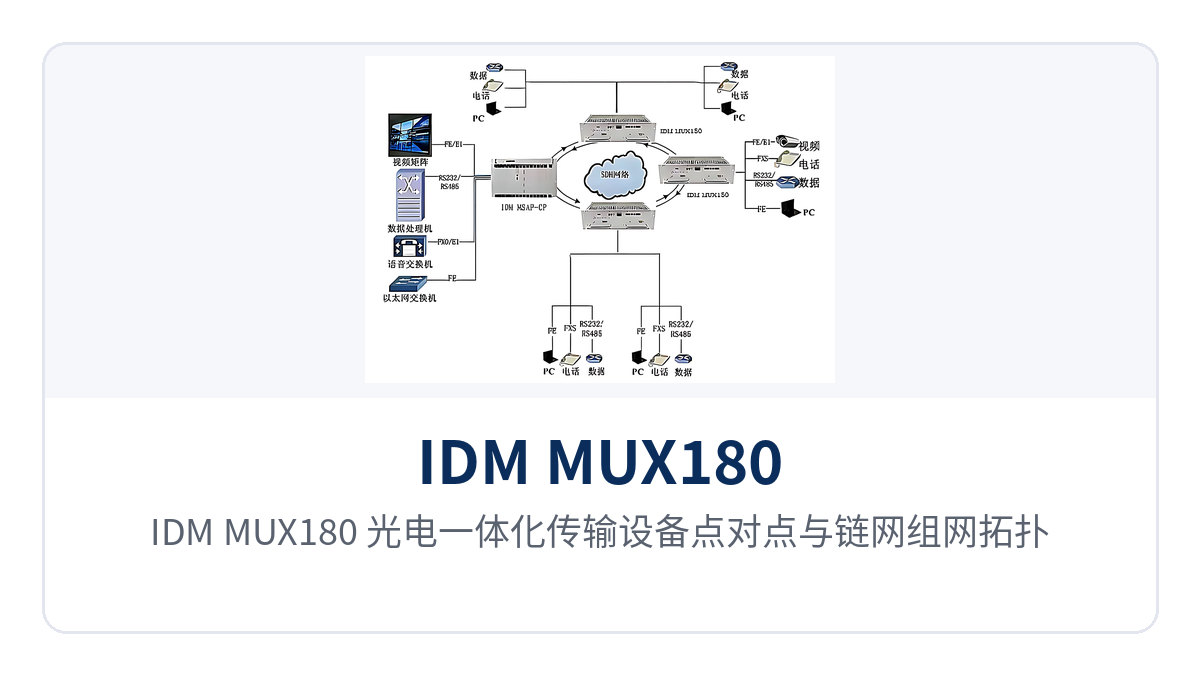
Figure 3: IDM MUX180 optical-electrical integrated transmission equipment point-to-point and chain network networking topology diagram
Electric Power and Rail Transit Private Networks: Multi-Service Backhaul over the Same Fiber for Substations and Stations Along the Line
Services from substations, switching stations and stations along rail transit lines to the dispatch center are mainly dispatch telephone, PA audio, telecontrol and monitoring data. The IDM MUX180 accesses these services by slot within the station and, through 24 E1 channels and cross-connection, delivers them onto the 155M optical line, so a single fiber backhauls voice and data simultaneously, reducing the number of incoming optical cables and wiring. As SDH equipment, its multiplexing capability at the optical transmission equipment level makes multi-service backhaul over the same fiber possible.
Most sites are unattended. The equipment is designed for -20℃+50℃ and 095% non-condensing humidity, can draw power directly from the station's -48V DC distribution panel, and its ≤90W overall power consumption places little discharge pressure on storage batteries. When a new bay or a new site is added, only service cards and time slot configuration are added, while the chassis and external wiring remain unchanged.
Military and Government Private Networks: Dual Power Supply Access and Rapid Field Setup
Power supply conditions at field command posts and temporary duty posts vary with the site, with mains power, generators and DC distribution panels coexisting. AC220V/DC-48V dual power supply allows the same device to be installed in cabinets of different power supply formats, so only one model needs to be kept as a spare, and no temporary power conversion device is needed when moving into different sites. This feature also gives the SDH equipment strong on-site adaptability in military emergency communications vehicle solutions.
The 17 user slots are configured according to the mission: telephone cards and E1 cards are inserted first to provide basic command voice channels, then Ethernet cards and audio cards are added as required. The 3U chassis fits into a standard cabinet or a vehicle-mounted rack, and the lifting and wiring workload for mobile setup decreases with the number of devices.
Unattended Sites in the Field for Oilfields and Mining Areas: 20Km Direct Connection and Low-Power Operation
Well sites, metering stations and mining area substations are distributed across a collection area tens of kilometers wide, and inter-site services are mainly telephone, payload data and monitoring. The single-mode 20Km optical port covers the spacing between adjacent sites, eliminating the need for an intermediate repeater equipment room and saving the power supply and attendance costs of repeater sites.
Field cabinets face high summer temperatures and unstable power supply conditions. The -20℃~+50℃ operating range and ≤90W overall power consumption reduce heat dissipation and backup power pressure, so solar power or a small-capacity storage battery can keep the equipment online over the long term. For longer links, long-distance optical modules can be fitted without affecting the time slots already enabled or other services.
Conclusion
Selection of access layer equipment ultimately comes down to three things: the link can be pulled through, the services can be configured, and the site can be kept running. As a 17-slot mixed-insertion optical-electrical integrated transmission device, the IDM MUX180 uses 17 user slots to handle the service mix, a 20Km single-mode optical port for direct inter-station connection, and ≤90W low power consumption with AC220V/DC-48V dual power supply for unattended power access. As an SDH equipment manufacturer, Raytrans continues to optimize the product showcase and configuration flexibility around private network access scenarios in the design of this series, and both government private network optical fiber communication solutions and military emergency communications vehicle solutions can rely on such optical transmission equipment for rapid deployment.
For electric power, rail transit, military and government, and oilfield and mining private network projects, a single 3U device handles access, multiplexing and transmission at the same time, reducing cabinet space, the number of patch cords and the variety of spare parts, making construction and O&M costs at the access layer easier to calculate. With a unified model, cross-line transfer and spare parts sharing also become simpler.