IDM MSG Magneto Gateway
Magneto voice channel directly to SIP, calls survive dual power supply failure, 1 WAN + 4 LAN saves one device
The IDM MSG OVER IP gateway is designed with large-scale dedicated integrated circuits and implements the transmission of one magneto telephone channel over Ethernet. The device's transmission mode can be selected as either one Ethernet electrical interface or one Ethernet optical interface; when the device uses an Ethernet electrical or optical interface, the maximum bandwidth is 100 M. The device supports WEB network management configuration, allowing modification of gateway server registration, IP address configuration, telephone call modes, and more through WEB pages.
The IDM MSG OVER IP dual-power-supply magneto gateway is an IP access gateway developed by Beijing Ruiguang Jiyuan Digital Technology Co., Ltd. (Raytrans). It consists of magneto telephone interfaces, Ethernet electrical or optical ports, and a SIP protocol stack, and is used to connect one magneto telephone channel to an Ethernet or optical fiber IP private network for transmission. It is a key access device in government private network optical fiber communication solutions and electric power substation magneto telephone access solutions.
Key Specifications at a Glance: 1–2-channel magneto telephone RJ11 interfaces · 1 WAN + 4 LAN or 1 optical + 4 electrical · 10/100M adaptive · SIP V1/V2 standard protocols · dual mutual-backup power supplies AC 220 V/DC -48 V · overall power consumption ≤5 W · latency ≤100 μs
Magneto telephones are still widely used in electric power substations, along railway lines, and in government private networks. These telephones use a hand-cranked generator to send ringing current and can still communicate during a power failure, yet the voice channel itself carries only analog audio and cannot be directly integrated into an IP-based dispatch network. Converting magneto voice channels into IP voice streams is an unavoidable step in magneto-to-SIP retrofit solutions; the focus of the retrofit is not the telephone but the gateway at the uplink side of the site that translates analog voice channels into SIP calls. As a professional command and dispatch system manufacturer, Raytrans offers this IP access gateway, which can coordinate networking with converged dispatching gateways and SIP telephones and is widely used in scenarios such as military emergency communications vehicle solutions. Its complete form is also shown in the product showcase.
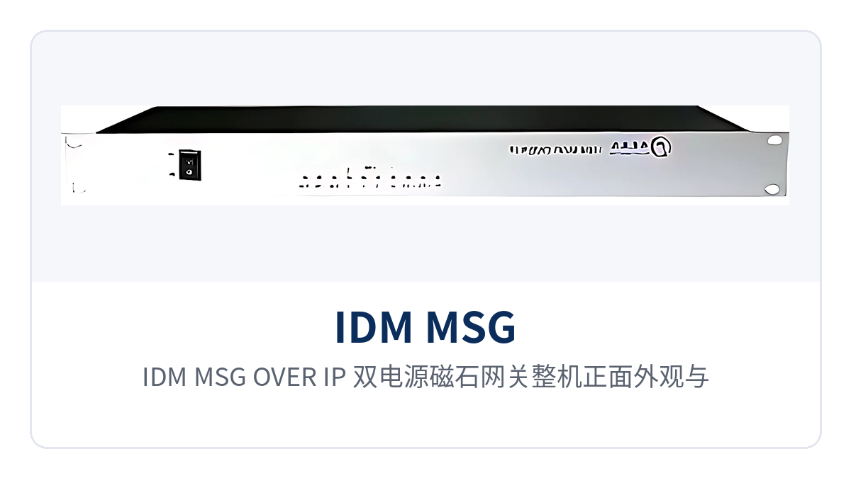
Figure 1: Front appearance of the IDM MSG OVER IP dual-power-supply magneto gateway and layout of power and Ethernet link indicator LEDs on the front panel
What the dual-power-supply magneto gateway is and how magneto voice channels are converted into SIP calls
The magneto interface uses transformer coupling, with an input and output impedance of 600 Ω. Voice, off-hook/on-hook status, ringing current, and other line states are carried on the same pair of wires. Transformer coupling isolates the telephone side from the internal circuits of the device, making it difficult for common-mode interference to enter the voice channel; sites with poor electromagnetic environments, such as substations and trackside equipment rooms, rely more on this isolation. As an IP access gateway designed for private network scenarios, the device performs bidirectional conversion of signaling and media between magneto voice channels and the IP network.
On the network side, the device translates line states into standard SIP signaling and packetizes voice into IP media streams. The uplink can use one Ethernet electrical interface or one Ethernet optical interface, both with a bandwidth of 100M. The SIP protocol supports V1 (RFC2543) and V2 (RFC3261), enabling interfacing with standard SIP softswitches or dispatch servers, and the device can also serve as a remote access unit of a converged dispatching gateway.
The unit uses a rack-mounted design and can be installed in a site communications cabinet. The magneto telephone side provides RJ11 interfaces. On the Ethernet side, the electrical port version provides five electrical ports (1 WAN plus 4 LAN), while the optical port version provides one optical port plus four electrical ports. In-station surveillance and office terminals can connect to the LAN ports nearby without an additional switch. For sites that need to connect SIP telephones, the LAN ports can also directly power and network the telephones.
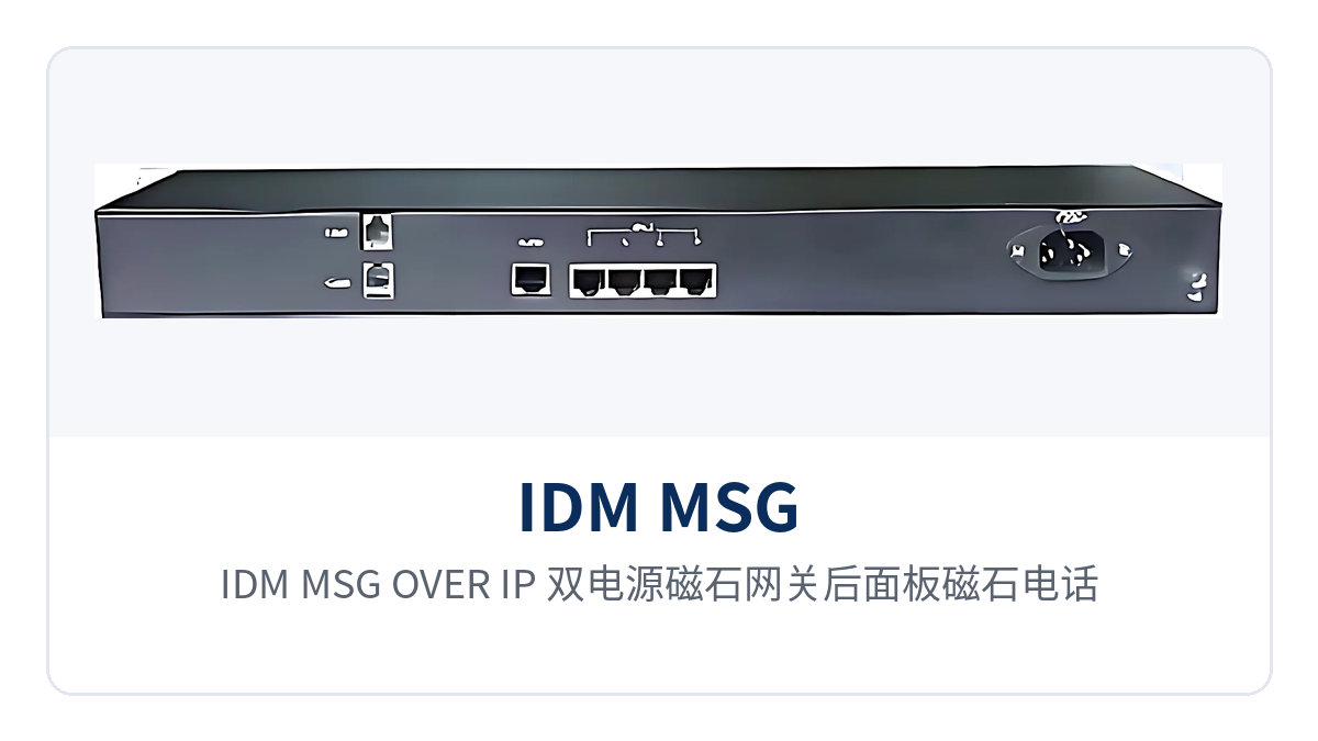
Figure 2: Rear panel layout of the IDM MSG OVER IP dual-power-supply magneto gateway with magneto telephone RJ11 interfaces and 1 WAN + 4 LAN Ethernet ports
Functions and configuration capabilities: SIP registration, phone book, and hotline transfer
The device's functions are grouped into four categories: voice channel access, call services, remote management, and on-site adaptation. Each function and its purpose is listed in the table below. When checking the service list on site, simply confirm row by row. Specific configuration items are completed on the WEB network management page, and parameter items are subject to the manufacturer's technical documentation. The network management interface that Raytrans provides for this product series organizes menus according to these four function groups.
| Function | Description |
|---|---|
| SIP V1/V2 standard protocols | Supports SIP V1 (RFC2543) and V2 (RFC3261), enabling interconnection with standard SIP softswitches and dispatch servers; magneto voice channels register with the network as SIP terminals |
| 1 WAN + 4 LAN or 1 optical + 4 electrical | The electrical port version provides five Ethernet electrical ports (1 WAN plus 4 LAN); the optical port version provides one optical port plus four Ethernet electrical ports, with 10/100M adaptive rates |
| 2-channel magneto telephone RJ11 interfaces | Provides two magneto telephone RJ11 interfaces, configured for use with one or two magneto voice channels, directly connecting to existing magneto telephones and magneto switching equipment |
| Magneto transformer coupling | The magneto interface uses transformer coupling with an input and output impedance of 600 Ω; the telephone side is electrically isolated from internal circuits to suppress common-mode interference |
| Call volume adjustment | Call volume is adjusted per voice channel on the network management page to suit the transmit and receive sensitivity of different telephones and line attenuation conditions |
| Phone book (20 contacts) | The phone book can store information for 20 contacts, allowing frequently used dispatch numbers to be dialed locally without dialing digit by digit each time |
| Call transfer, hotline, and do not disturb | Supports call transfer, hotline, and do not disturb; the hotline dials a preset number as soon as the phone goes off-hook, and do not disturb blocks non-dispatch incoming calls |
| WEB network management and registration status query | Log in to the WEB page through the WAN port to configure the IP address, SIP server registration, and call mode, and to query the SIP registration status of central office and remote-end devices |
Key specifications: magneto interfaces, Ethernet interfaces, and power supply environment
Specifications are listed by group: magneto interfaces, Ethernet interfaces, and power supply and environmental conditions. Values are taken from product documentation and can be directly cited in on-site design and acceptance. The order of verification is to first determine the number of voice channels and the uplink form, then check the power supply format and cabinet environment, and finally calculate link latency and packet loss based on actual measurements.
| Item | Parameter/Specification | Description/Applicable Conditions |
|---|---|---|
| Magneto telephone interfaces | 2× RJ11, configured for use with 1 or 2 channels | Connects to magneto telephones and magneto switching equipment; voice channels are carried over Ethernet |
| Magneto interface coupling mode | Transformer-coupled | The telephone side is electrically isolated from internal circuits |
| Magneto interface impedance | Input and output impedance 600 Ω | Matches common magneto telephones and magneto trunk interfaces |
| Ethernet interface configuration | 5 electrical ports (1 WAN + 4 LAN) or 1 optical port + 4 electrical ports | Choose the electrical or optical port version according to the site's uplink resources |
| Ethernet standard | IEEE 802.3 10/100BASE-TX | Direct connection to in-station switches and terminals |
| Transmission rate | 10/100 Mbit/s adaptive, adaptive by default | Rate is set through network management |
| Operating mode | Full-duplex/half-duplex, full-duplex by default | Supports auto-negotiation, rate, and duplex configuration |
| Interface type | RJ45, CAT3/5 unshielded twisted pair, MDI/MDI-X adaptive | Direct network cable connection; no crossover cable required |
| Ethernet frame length | Standard 64–1516 bytes, single-frame upper limit 1516 bytes | Verify against service packet length |
| Ethernet performance standard | RFC2544 performance | Acceptance testing follows RFC2544 |
| Packet loss rate and latency | Packet loss rate <0.01%, latency ≤100 μs | Factory test basis; on-site actual measurements prevail |
| SIP protocol versions | SIP V1 (RFC2543), V2 (RFC3261) | Configure according to the version supported by the softswitch side |
| Power supply mode | AC 220 V or DC -48 V, dual mutual-backup power supplies | Both power feeds connected simultaneously; select according to in-station power conditions |
| Overall power consumption | ≤5 W | Unit power draw at full configuration |
| Operating temperature | 0 °C to 40 °C for long-term operation, -5 °C to 45 °C for short-term operation | Short-term means no more than 24 consecutive hours and no more than 15 days per year in total |
| Transportation and storage temperature | 0 °C to 70 °C | Warehousing and transportation |
| Relative humidity | 95% (non-condensing) | For use in non-condensing environments |
| Structure | Rack-mounted design | Installed in a site communications cabinet; panel indicator LEDs show status |
The differentiated capabilities lie in three areas: power supply, magneto interfaces, and Ethernet configuration. The three items, their corresponding capabilities, and customer value are shown in the table below. The capability descriptions in the table are taken from product documentation; specific wiring and configuration are subject to on-site conditions and commercial confirmation. None of the three capabilities involves replacing telephones or cabling; after the retrofit, the differences are concentrated in the in-station power supply access and the uplink interface form.
| Differentiation Point | Corresponding Capability | Customer Value |
|---|---|---|
| Dual mutual-backup power supplies | AC 220 V and DC -48 V power feeds connected simultaneously; if one feed fails, the other supports operation; overall power consumption ≤5 W | Unattended sites do not need an inverter or dual-power-supply transfer device for the gateway; both the DC distribution panel and AC mains power can supply power directly, reducing the discharge burden on storage batteries |
| Magneto transformer coupling | Transformer-coupled magneto interface with input and output impedance of 600 Ω | Substations and trackside equipment rooms have strong common-mode interference; after transformer isolation, crosstalk and noise on voice channels are reduced, and call clarity remains stable |
| 1 optical + 4 electrical and latency ≤100 μs | Electrical port version 1 WAN + 4 LAN; optical port version 1 optical port + 4 electrical ports; 10/100M adaptive; packet loss rate <0.01%, latency ≤100 μs | One optical fiber delivers voice channels to the equipment room at the remote end; in-station surveillance and office terminals connect to LAN ports nearby; dispatch call latency and packet loss remain within acceptable ranges on the private network |
How to connect the magneto gateway to an IP private network: wiring, configuration, and commissioning steps
The procedure for connecting magneto telephones to an IP private network consists of five steps: wiring, address configuration, registration, service adjustment, and verification, all completed on the site side. Existing magneto telephones and cabling do not need to be replaced. Before commissioning, verify the telephone numbers, server addresses, uplink form, and in-station power conditions clearly, and on-site rework can basically be avoided.
- Connect telephones: Connect magneto telephones to the device's magneto interfaces via RJ11, configured for 1 or 2 channels. Before wiring, confirm that the telephones are magneto type and that ringing current is supplied by the telephone's hand-cranked generator.
- Select uplink: If usable optical fiber is available at the site, choose the optical port version and connect one optical fiber to the equipment room side; if only network cable resources are available, choose the electrical port version, uplink the WAN port to the private network, and connect the 4 LAN ports to in-station terminals.
- Configure addresses: Log in to WEB network management through the WAN port and set the management IP and gateway addresses; SIP registration parameters for central office and remote-end devices are configured on the same page.
- Register: Enter the SIP server address and telephone number, select SIP V1 or V2 according to the version supported by the softswitch side, and check whether the registration status is online after saving.
- Adjust services: Adjust call volume according to on-site conditions, enter phone book contacts, and enable hotline, do not disturb, and call transfer as needed.
- Verify: Use the magneto telephone to place test calls to central office and remote-end numbers, check for intermittent audio, echo, and one-way audio, and record packet loss and latency test results for archiving.
Power supply and installation are completed in the same construction session, with the enclosure fixed before wiring. Select AC 220 V or DC -48 V according to in-station conditions; connecting both feeds simultaneously forms dual mutual-backup power supplies. Wiring terminals and polarity are subject to the accompanying technical documentation. After the rack-mounted enclosure is installed in the communications cabinet, the front panel indicator LEDs show power and Ethernet link status, so on-duty personnel can see alarms while standing in front of the cabinet without opening the cover.
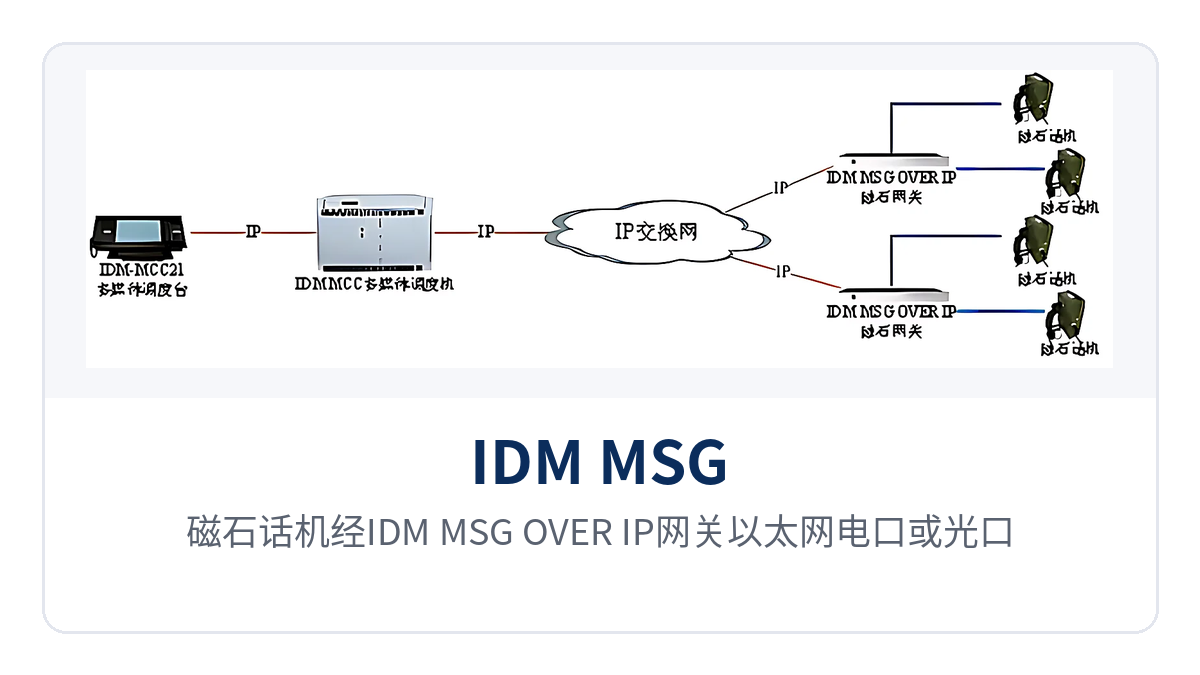
Figure 3: Point-to-point networking diagram of magneto telephones accessing an IP private network through the IDM MSG OVER IP gateway via Ethernet electrical or optical ports
Typical application scenarios
The common features of the three scenarios are distributed sites, long-term unattended operation, and the need for voice channels to reliably reach the dispatch center, while the uplink resources available at the sites are often only existing optical fiber or a single network cable. A dual-power-supply magneto gateway at the site side converts magneto voice channels into IP voice streams; the retrofit touches only the uplink side, not the telephones or cabling, keeping in-station construction work and power outage coordination time to a minimum.
Electric power private network: dispatch voice channel backhaul for substations and switching stations
In substations, switching stations, and distribution rooms, magneto telephones are installed in duty rooms and equipment rooms, sending ringing current via hand-cranked generators so that calls remain possible during station power failures. The IDM MSG OVER IP dual-power magneto gateway connects such voice channels to the station IP network and then sends them over existing optical fiber to the dispatch center, where dispatchers manage unified numbering and recording as SIP terminals. This magneto voice channel-to-SIP transformation solution is a typical practice in magneto telephone access solutions for electric power substations, and the scope of transformation is limited to the uplink side.
The electromagnetic environment and power supply conditions at electric power sites are less than ideal: the transformer-coupled 600 Ω magneto interface isolates voice channels from station circuits, making it difficult for common-mode interference to couple in; dual mutual-backup AC220V and DC-48V power supplies allow direct power supply access from both the station DC distribution panel and AC mains power, and power consumption of ≤5 W has almost no impact on storage battery backup time.
Rail Transit: Voice Access for Trackside Sites and Trackside Equipment Rooms
Trackside sites and trackside equipment rooms along rail transit lines are distributed in a belt shape, with inter-station distances ranging from several hundred meters to several kilometers, and section optical cables laid along the line. At the site side, magneto telephones are connected to the gateway, and the optical port form is sent over section optical cables to the station communications equipment room, where the equipment room side then integrates into the IP-based official telephone and dispatch system.
Temperature differences and dust in trackside cabinets are real challenges for the equipment. After the rack-mounted structure is installed in the cabinet, status is read via panel indicator LEDs, so O&M personnel conducting inspections along the line do not need to open each unit. When section optical cables are cut by construction, voice channels can be restored via the station's backup channel, and the transformed voice link no longer depends on the complete route of analog audio cables.
Military and Government Private Networks: Voice Fallback for Mobile Command Posts and Unattended Sites
Mobile command posts, duty posts, and field sites of military and government private networks face power supply conditions that vary with the site, with mains power, generators, and DC distribution panels coexisting, and no dedicated maintenance personnel. Dual mutual-backup AC220V and DC-48V power supplies allow the same device to be installed in cabinets of different power supply formats, and only one model of spare parts needs to be stocked. Such military emergency communications vehicle solutions and government private network optical fiber communication solutions have different requirements for the uplink form, so during selection the optical port or electrical port can be determined according to on-site resources.
Magneto voice channels are the fallback means in such scenarios: the telephone has built-in hand-cranked generation and local ringing current, and only digitized voice is transmitted over the link, without relying on external switch feeding. Enabling only requires connecting the telephone at the site side and configuring the IP and SIP registration; O&M personnel can remotely query the registration status through the WAN port, without having to drive to the site each time.
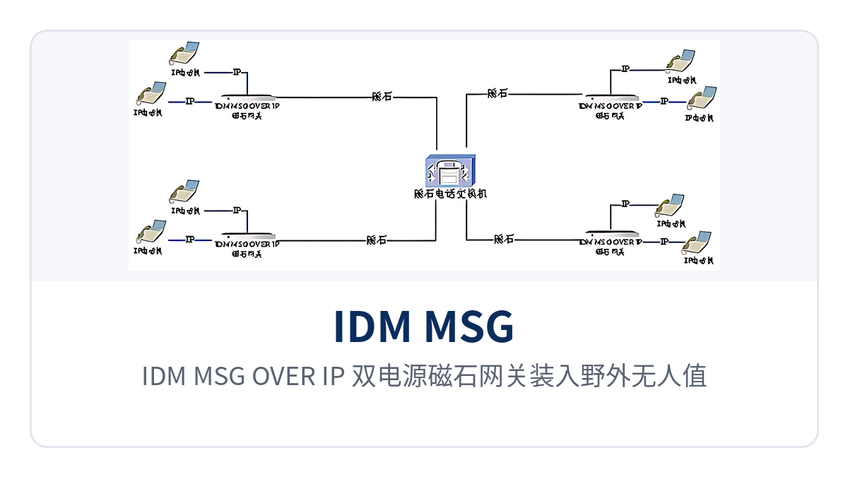
Figure 4: Close-up of the IDM MSG OVER IP dual-power magneto gateway installed in an outdoor unattended site cabinet and the AC220V/DC-48V dual-power supply power terminals
Conclusion
As an access device that delivers magneto voice channels onto an IP private network, the IDM MSG OVER IP dual-power magneto gateway uses a transformer-coupled 600 Ω magneto interface to connect to existing telephones, completes the uplink via an Ethernet electrical port or optical port, and supports long-term operation of unattended sites with dual mutual-backup AC220V/DC-48V power supplies and ≤5 W power consumption. The key to IP transformation of magneto telephones lies not in replacing the telephones, but in whether this layer of conversion at the site side is stable.
During selection, first verify the number of voice channels and the uplink form, then confirm the three conditions of power supply format, cabinet space, and electromagnetic environment, and then determine the number of units to deploy according to the number of sites. For projects in electric power, rail transit, and military and government private networks, it is recommended to include packet loss and latency indicators in the acceptance terms, test on site according to RFC2544 and keep the results on file; link conditions and configuration parameters are subject to the manufacturer's technical documentation and commercial confirmation.