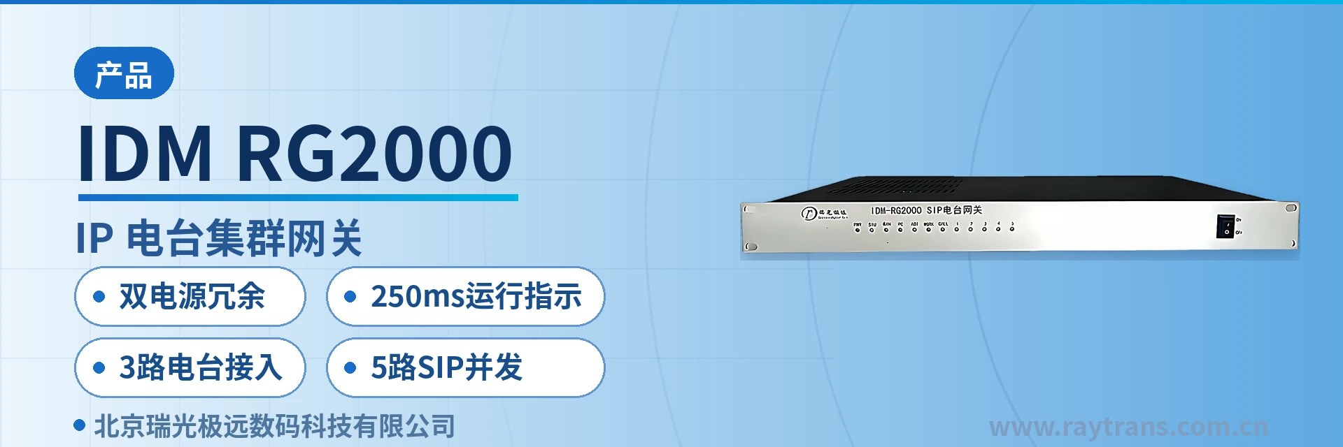
IDM-RG2000 SIP Radio Trunking Gateway
3 radio channels, 5 concurrent SIP calls, voice and PTT hosted on one device, 6-party voice conference
The IDM-RG2000 SIP radio trunking gateway is used in the product showcase domain and is intended for industry customers' communication/transmission/dispatch equipment (details to be refined based on documentation).
The IDM-RG2000 SIP radio trunking gateway is a gateway with 3 radio access ports and 5 concurrent SIP calls, developed by Beijing Ruiguang Jiyuan Digital Technology Co., Ltd. (Raytrans). It connects VHF base station radios and trunking radio sets to a SIP softswitch dispatch network, and is an IP access gateway device for wireless and SIP convergence scenarios in the product showcase. On one side, the device connects to the dispatch server and dispatch console through a SIP trunk; on the other side, it connects the audio and parameter control lines of the base station radios through radio interfaces 1 to 3, enabling bidirectional voice intercommunication between dispatch telephones and radio sets and supporting calls between trunking intercom and SIP telephones.
The unit is a 19-inch 1U chassis with dual redundant power inputs, and the front panel houses the power, CPU operating, status, WAN port and PC port indicator LEDs. The panel LEDs reflect three categories of status: power supply, operation and connectivity, so operating status can be read directly from the indicators in front of the cabinet.
For command and dispatch projects that need to connect base station radios to the SIP dispatch telephone network and expect the device to run long-term at unattended sites, selection can be checked against the capacity of 3 radio access ports and 5 concurrent SIP calls. As an IP access gateway product from the command and dispatch system manufacturer Raytrans, the device serves three scenarios: smart mining communication solutions, military emergency communications vehicle solutions and government private network optical fiber communication solutions. After in-cabinet installation in the station building, dispatchers can reach radio channels through the dispatch console or SIP telephones.
Key Specifications at a Glance: dual redundant power supply · 250ms operating indication · 3 radio access ports · 5 concurrent SIP calls · 6-party voice conference room · 19-inch 1U chassis
What is a gateway with 3 radio access ports and 5 concurrent SIP calls? What role does it play in a dispatch system?
A gateway with 3 radio access ports and 5 concurrent SIP calls is an access conversion device between radio sets and the IP dispatch network, and its role is to remove the format gap between the wired telephone network and the radio network. As an IP access gateway for command and dispatch scenarios, the IDM-RG2000 SIP radio trunking gateway converts the voice and PTT signaling of base station radios into SIP signaling and media streams, so that dispatch telephones, SIP telephones and VHF radios can call each other and hold group conferences and broadcasts on the same dispatch line, providing a unified access channel for trunking intercom and cross-network calls.
The device consolidates voice channels that originally belonged to two separate systems into one 1U chassis, so radio duty operator seats and telephone dispatch seats can be merged, and cross-network calls no longer depend on manual patch cords.
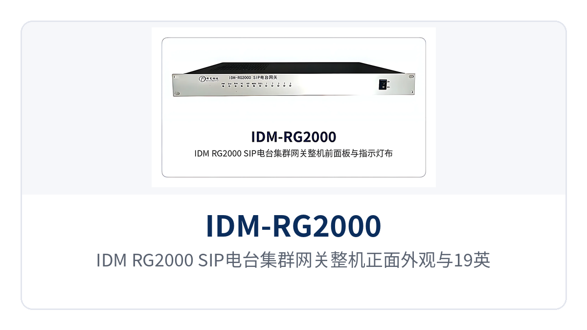
Figure 1: Front view of the IDM-RG2000 SIP radio trunking gateway and its 19-inch 1U chassis
Voice and radio control are hosted on one gateway, so no separate devices are needed for the two services. The IDM-RG2000 SIP radio trunking gateway registers with both the SIP voice dispatch server and the IoT communication server: the SIP softswitch protocol handles calls, transfer and conferencing, while the MQTT IoT protocol handles the delivery of parameters such as PTT commands, radio frequency and transmit power.
The dispatch end calls radios by number on the dispatch console, while the O&M end changes frequency and adjusts power remotely on the management platform; the two channels use their own protocols and do not contend for voice resources.
In the traditional approach, radio duty and telephone dispatch are separate, and duty operators rely on manual transfer and multiple parallel intercoms to intercommunicate, which takes up cabinet space and easily misses calls. The IDM-RG2000 SIP radio trunking gateway combines voice bridging, conference organization and radio parameter control in one device, so cross-network intercom no longer requires extra dispatch lines or manual patch cords, and duty seats are streamlined accordingly.
How many radios and how many telephone lines can one device connect? Function and interface list
The functions of the IDM-RG2000 SIP radio trunking gateway are organized around radio access, cross-network voice intercommunication and device status visualization, and all capabilities are available simultaneously on one device. The table below lists the specific interfaces and capabilities by function item for item-by-item checking against the on-site configuration.
Function | Description |
|---|---|
Radio access | Provides radio interfaces 1 to 3 (RJ45 connector), connecting 3 base station radios per unit, with each radio corresponding to an independent audio channel and a parameter control serial channel |
SIP cross-network intercom | Connects radio voice to the dispatch network through the SIP softswitch protocol, enabling bidirectional voice intercommunication among dispatch telephones, the dispatch console and radios |
5 concurrent SIP calls | One device provides 5 concurrent SIP calls, and each radio has a dedicated SIP hotline channel to the dispatching exchange |
6-party voice conference room | Each radio corresponds to a 6-party voice conference room, and one radio can speak online with 5 concurrent SIP calls at the same time |
FXO trunk access | Provides 2 FXO trunk telephone interfaces to connect PSTN or SPC exchange lines to the system, so outside line telephones can also join radio dispatch calls |
MQTT remote control | Sets radio frequency, adjusts transmit power and delivers PTT commands remotely through the MQTT IoT protocol |
Radio protocol self-learning | Automatically learns radio commands for power increase/decrease, transmit and receive frequency switching and antenna pointing control, so multiple radio models can be connected without modification |
Dual redundant power supply | Two independent power feeds are connected separately; if either feed fails, the other continues to supply power, and the power indicator shows whether power supply is normal |
Status visualization | Power, CPU operating, status, WAN port, PC port, WORK and CALL indicator LEDs are grouped on the front panel, so operating status can be read directly |
Ethernet interface | Provides an RJ45 Ethernet electrical interface and an FS optical interface, supporting 10/100BASE-T and 10/100BASE-FX |
Management interface | Provides an RJ45 management interface for local configuration and maintenance |
How are the panel indicator LEDs read? What do 250ms flashing and alternating red and green mean?
The IDM-RG2000 SIP radio trunking gateway brings all three categories of status — power supply, operation and connectivity — to the front panel, so O&M personnel can judge whether the device is currently normal without connecting a maintenance computer. The reading order is power indicator first, then operating indicator, then network indicators; the complete indicator definitions are given in the table below.
Indicator LED | Color | Function | Status Description |
|---|---|---|---|
PWR | Green | Power indicator | The LED is on when the system power supply is normal and off when the power supply is abnormal |
ACT | Green | Operating indicator LED | It blinks at intervals of about 250ms when the CPU is working normally, and stays on or off when the CPU is abnormal |
STU | Green, red | Status indicator LED | The LED stays red when the WAN port has not obtained an IP address (no network cable connected, DHCP address acquisition failure, IP address conflict, PPPoE dial-up failure, etc.); it blinks alternately red and green when the connection is normal |
WAN | Green | WAN port indicator LED | It stays on when a WAN connection is established but there is no service traffic, and blinks when there is service traffic |
PC | Green | PC port indicator LED | It stays on when the link is up but there is no service traffic, blinks when there is service traffic, and is off when the link is down |
WORK | Green | WORK indicator LED | It blinks when the device is operating normally |
CALL | Green | CALL indicator LED | It blinks when the device is operating normally |
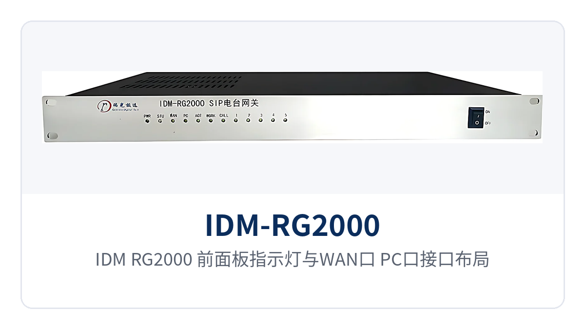
Figure 2: Close-up of the IDM-RG2000 front panel indicator LEDs and the WAN and PC port layout
Three types of LEDs correspond to three types of judgment: if the power LED PWR is off, the power supply is abnormal, and the two power feeds should be checked first; if the operating LED ACT does not blink at intervals of about 250ms, the CPU is working abnormally; if the status LED STU stays red, the WAN port has not obtained an IP address. If the green LEDs of the WAN port and the PC port stay on, the link is up but there is no service traffic for the moment; if they blink, services are being transmitted; if they are off, the link is down.
Alternate red and green blinking of the STU status LED indicates a normal connection. When the red LED stays on, troubleshoot in the following order:
Check whether the network cable of the WAN port is properly connected and whether the port of the opposite-end device is normal;
Check whether the uplink network distributes addresses normally and whether the DHCP service is reachable;
Check whether the device address conflicts with the IP address of another device;
For lines using PPPoE dial-up, check whether the dial-up account and password are correct.
After the address is obtained successfully, the status LED resumes alternate red and green blinking, and the WAN port indicator LED turns to blinking when there is service traffic. Panel interpretation does not rely on any dedicated tool; inspection personnel can complete preliminary positioning while standing in front of the cabinet.
The 250ms operating indication is the direct basis for judging whether the CPU is working normally. Blinking at intervals of about 250ms indicates that the CPU is working normally, while steady on or steady off indicates an abnormality. In an unattended field equipment room, opening the cabinet and checking the LEDs distinguishes power supply problems from device problems without first connecting a maintenance computer. Used together, the dual power supply redundancy and the 250ms operating indication can reduce both downtime and the number of attendance on site.
Key Specifications and Performance Indicators
The interface and performance parameters of the IDM-RG2000 SIP radio trunking gateway are subject to the product documentation of Raytrans. The following table summarizes the definite specifications on the radio side, the telephone side and the network side for reference in product showcase selection and networking design.
Item | Parameter/Specification | Description/Applicable Conditions |
|---|---|---|
Radio access capacity | 3 channels; a single unit connects 3 base station radios | Each radio channel corresponds to an independent audio channel and a parameter control serial channel |
Radio audio interface | 3 channels, transformer-coupled | Input/output impedance 600 Ω; receive/transmit gain adjustable, 0 dB transmit and 0 dB receive by default; balanced input, can be configured as unbalanced (one end grounded) |
Telephone trunk interface | 2 FXO channels, transformer-coupled | Interface impedance 200 Ω + 680 Ω//0.1 μF three-element impedance; 600 Ω pure resistance available on request |
Concurrent SIP calls | 5 | Each radio has a fixed SIP hotline channel to the dispatching exchange, plus 1–2 SIP channels that can be switched to any radio |
Conference capability | 6-party voice conference room, independent per radio | One radio can talk online with 5 concurrent SIP calls at the same time |
Network interface | WAN port, PC port, management interface (RJ45) | The WAN port connects to the uplink IP network and obtains an address through DHCP or PPPoE; the PC port is a local Ethernet interface; the management interface is used for local configuration and maintenance |
Ethernet electrical interface | 10/100BASE-T, full-duplex/half-duplex adaptive | Compliant with IEEE 802.3, 802.1P and 802.1Q; RJ45 connector, 100M Category 5 twisted pair |
Ethernet optical interface | 10/100BASE-FX, FS interface | Transmit power ≥ -5 dBm, receiver sensitivity ≤ -35 dBm; wavelength 1310/1550 nm; transmission distance 10 km and 40 km, up to 120 km |
Control interface | Asynchronous, 8 data bits, 1 stop bit, no parity | Baud rate 57600, used for radio parameter control and protocol self-learning |
Signaling protocol | SIP softswitch protocol, MQTT IoT protocol | MQTT supports PTT command transmission, serial port radio frequency management and radio power setting |
Panel indication | PWR, ACT, STU, WAN, PC, WORK and CALL indicator LEDs | Power, operating, connection and service status are displayed together; see the indicator LED table above for specific status definitions |
Power supply mode | Dual power supply redundancy access | Two independent power feeds are connected separately; if either feed fails, the other continues to supply power; the voltage format and overall power consumption are subject to the manufacturer's technical documentation and commercial confirmation |
Enclosure | 19-inch standard 1U | Dimensions 170×437.6×44 (mm), suitable for installation in a standard cabinet |
Operating environment | Not yet recorded in the knowledge base | Subject to the manufacturer's technical documentation and commercial confirmation |
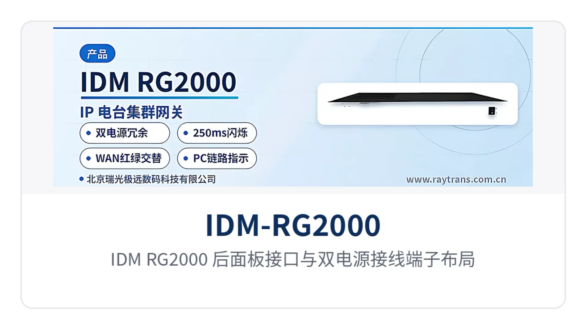
Figure 3: IDM-RG2000 Rear Panel Interfaces and Dual Power Supply Terminal Layout
Dual power supply redundancy access determines the availability of the device under the power supply conditions of a station building. Two independent power feeds are connected separately to the enclosure; if either feed fails, the other continues to supply power, so the private network equipment does not go down. The PWR power indicator LED reflects whether the power supply is normal; it goes off and raises an alarm on any abnormality. During engineering survey, confirm that the station building can provide two independent power feeds taken from different distribution circuits; otherwise the redundancy is only a nominal backup.
Differentiated Value: Dual Power Supply Redundancy, 250ms Operating Indication and 3 Radio Channels with 5 Concurrent SIP Calls
The differentiated capabilities of the IDM-RG2000 SIP radio trunking gateway focus on three aspects: power supply reliability, operating status visibility and access capacity. The correspondence between the four short labels and customer value is shown in the table below. These designs target scenarios with high continuity requirements, such as smart mining communication solutions, military emergency communications vehicle solutions and government private network optical fiber communication solutions, and are also the capabilities that Raytrans highlights in its product showcase.
Differentiation Point | Description and Customer Value |
|---|---|
Dual power supply redundancy: two independent power feeds connected separately | If either feed fails, the other continues to supply power, so the private network equipment does not go down; the power indicator LED reflects whether the power supply is normal and goes off with an alarm on any abnormality, so the station building does not need a special trip for a single power supply failure |
250ms operating indication: the CPU operating LED blinks at 250ms | Steady on or steady off indicates an abnormality; unattended sites can locate faults by the LED, and inspection personnel can judge at the cabinet whether spare parts need to be replaced |
3 radio channels: a single unit connects 3 base station radios | Each radio channel corresponds to an independent audio channel and a parameter control serial channel; one 1U device takes on the work of multiple single-channel gateways, reducing cabinet space and cabling at the same time |
5 concurrent SIP calls: 5 concurrent SIP calls | Each radio has an independent 6-party voice conference room, and one radio can talk online with 5 concurrent SIP calls at the same time, so dispatching, duty and on-site multi-party consultation do not have to queue for the channel |
The three selling points come down to the same operating actions: connect power, check the LEDs, dial. The IDM-RG2000 SIP radio trunking gateway puts dual power supply redundancy access, 250ms operating indication, 3 radio channels and 5 concurrent SIP calls into one 1U device. The dispatcher calls a radio by number, and O&M personnel judge the status by the LEDs; neither needs additional middleware or dedicated tools.
Typical Application Scenarios: How to Connect Smart Mining, Emergency Communications Vehicles and Government Private Networks
The typical networking of the IDM-RG2000 SIP radio trunking gateway is to connect base station radios and trunking radios to the SIP dispatch network, forming a communication system in which telephones, softswitch terminals and radio sets are uniformly dispatched between the dispatch equipment room and remote station buildings. The device is deployed in the dispatch equipment room or in a cabinet at the station building, and on the radio side the audio and parameter control lines of the base station radios are connected through radio interfaces 1 to 3.
How Are Underground Radios Connected in a Smart Mining Communication Solution?
In a smart mining communication solution, underground and surface VHF radio sets and trunking intercoms often belong to systems separate from the surface dispatch telephones. The IDM-RG2000 SIP radio trunking gateway is installed in a cabinet in the pithead dispatch equipment room, connecting surface base station radios and underground repeater radios to the SIP dispatch network. The dispatch console calls any radio channel by number, and multiple SIP phones can join the radios in a 6-party conference to issue shutdown, evacuation and maintenance instructions.
Dual power supply redundancy keeps dispatching uninterrupted when one power feed is under maintenance, and the 250ms operating indication lets inspection staff confirm device status by the indicator LEDs at an unattended pithead equipment room.
How Is Front-to-Rear Communication Ensured on a Military Emergency Communications Vehicle?
In a military emergency communications vehicle solution, vehicle-mounted VHF base station radios and trunking radio sets need to access the rear command and dispatch system both while moving and while parked. The IDM-RG2000 SIP radio trunking gateway is installed in the communication vehicle cabinet in a 19-inch 1U form factor. On the radio side it connects to the vehicle-mounted base station radios; on the network side it backhauls through the WAN port over a vehicle-mounted satellite or 4G link; on the SIP side it interfaces with the softswitch at the command center, enabling bidirectional voice intercommunication between the front and the rear.
Under operating conditions such as in-vehicle power switching and generator start/stop, dual power supply redundancy ensures calls continue when either feed loses power, and the indicator LEDs alone confirm whether the device is operating normally.
How Far Can a Government Private Network Optical Fiber Communication Solution Transmit?
In a government private network optical fiber communication solution, optical cables have usually already been laid between station buildings along the line and the command center. The network side of the IDM-RG2000 SIP radio trunking gateway provides 10/100BASE-FX optical interfaces with transmission distances of 10 km and 40 km, up to 120 km, so radios at station buildings can uplink directly to the dispatch center through the optical port without pulling a separate Ethernet cable to each station building.
When a remote station building is unattended, the MQTT channel allows remote frequency change, power adjustment and PTT command delivery, and together with panel indicator LED reading it reduces personnel travel.
Selection and Deployment Recommendations
Before deployment, first take stock of the number of radio channels and frequency bands to be connected, check the configuration against the capacity of 3 radio channels and 5 concurrent SIP sessions, and confirm whether the station building can provide two independent power feeds. For the network side, select 10/100BASE-T electrical ports or 10/100BASE-FX optical ports according to the distance between the station building and the dispatch center; optical port transmission distances are 10 km, 40 km and up to 120 km. Reserve 19-inch 1U space in the cabinet; dimensions are 170×437.6×44 mm. As a typical configuration in the IP access gateway product showcase, the device can handle the access aggregation of trunking intercoms and SIP telephones, providing a reference for subsequent selection by command and dispatch system manufacturers; Raytrans has corresponding deployment experience in smart mining communication solutions, military emergency communications vehicle solutions and government private network optical fiber communication solutions.
On-site troubleshooting follows three steps: power, operation and connection:
First check whether the PWR power indicator LED is lit to determine whether both power feeds are normal;
Then confirm whether the ACT operating indicator LED blinks at about 250ms intervals to determine whether the CPU is working normally;
Then check whether the STU status indicator LED blinks alternately red and green and whether the WAN port and PC port indicator LEDs match the actual services.
This reading method requires no maintenance computer connection and suits unattended sites and station buildings with long inspection intervals. When selecting a gateway with 3 radio channel access and 5 concurrent SIP sessions for a project, verify the four items of radio channel count, SIP concurrency, FXO trunk and optical port distance to complete the access planning for one device; engineering parameters such as the operating environment are not yet recorded in the knowledge base, and the manufacturer's technical documentation and commercial confirmation shall prevail.