IDM MSAP8000 Integrated Service Transmission Equipment
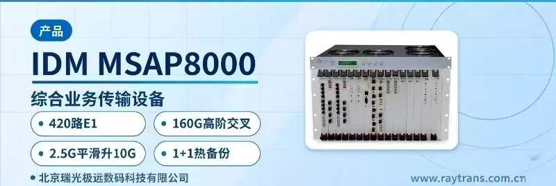
160G cross-connect, standalone unit with 420 E1 channels, 300 PCM channels, 14 slots for adding boards
The SDH optical transmission equipment is an STM-16/STM-64 multi-service transmission equipment that fully takes into account the diversity of network services and changes in network structure, inheriting Raytrans's expertise in the SDH/MSTP field.
The IDM MSAP8000 160G cross-connect multi-service transmission equipment is an STM-16/STM-64 multi-service transmission equipment developed by Beijing Ruiguang Jiyuan Digital Technology Co., Ltd. It integrates ADM add/drop multiplexing, DXC cross-connection, Ethernet switching, and PCM multiplexing into a single 19-inch 7U chassis, and is used for the construction and capacity expansion of transmission backbones and for high-capacity metropolitan service scheduling. It is Raytrans's representative SDH equipment on its optical transmission equipment product line.
The number of units in a backbone equipment room is usually determined by the termination method of edge services and the number of cross-connect layers. The IDM MSAP8000 uses a higher-order 160G / lower-order 20G cross-connect matrix for scheduling, while terminating 420 E1 channels and 300 channels of 64K PCM service in 14 service slots. One 7U unit does the work that previously required multiple narrowband multiplexing devices, visually demonstrating the integrated advantage of one unit serving multiple functions in the product showcase.
SDH equipment selection often comes down to three questions: how much edge service can be terminated, how much space is occupied in the cabinet, and whether capacity expansion requires replacing the entire unit. As a professional SDH equipment manufacturer, Raytrans gives the corresponding answers: 420 E1 channels terminated per unit, a 19-inch 7U footprint, and capacity expansion by adding boards to the 14 service slots, while the chassis, backplane, and external optical cables remain unchanged during expansion.
Configuring boards according to existing services initially and adding boards according to increments later is a common deployment rhythm for this equipment in private network projects. Electric power private networks, rail transit communication solutions, and military and government private networks at backbone nodes usually require high-capacity time-slot cross-connection, high-density edge service termination, and unit-level redundancy protection at the same time, and these three requirements must be met within one unit. Combined with MSTP multi-service transmission capabilities, Raytrans can also provide overall packages for government private network optical fiber communication solutions and military emergency communications vehicle solutions.
Key Specifications at a Glance: STM-64 rate · higher-order 160G / lower-order 20G cross-connect · 14 service slots with mixed insertion · 420 E1 channels + 300 channels of 64K PCM per unit · dual bus + 1+1 hot standby for boards · 19-inch 7U, typical power consumption <200W
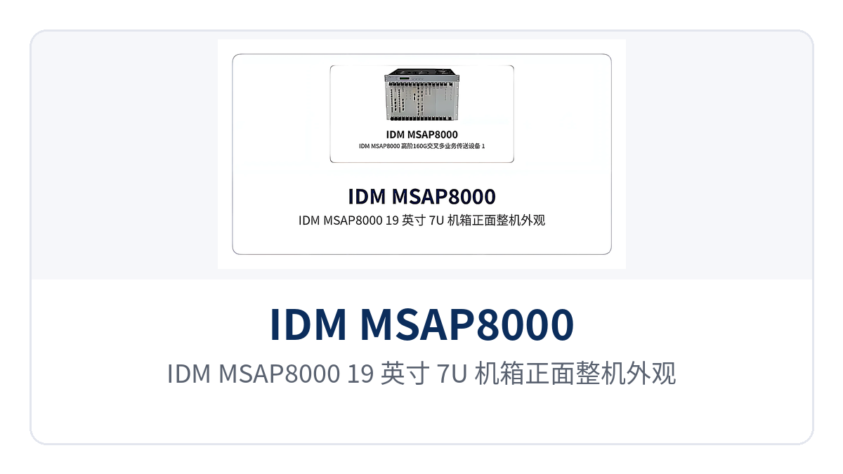
Figure 1: Front view of the IDM MSAP8000 19-inch 7U chassis showing the overall appearance and the silkscreen labels of the 14 service board slots
What services can the 160G cross-connect multi-service transmission equipment access?
Access capacity can be checked at three layers: optical direction, circuit service, and data service. On the optical direction side, STM-64, STM-16, STM-4, and STM-1 optical ports are supported; a 10G system can be configured with 4 10G optical directions, and a 2.5G system with 16 2.5G optical directions.
The circuit side carries E1 and 64K services, and the data side carries FE, GE, and EOS interfaces. All three service types enter the same cross-connect matrix for scheduling, so narrowband voice no longer requires a separate PCM layer, and the number of access-side units and the variety of spare parts are reduced accordingly.
The equipment concentrates optical transmission, time-slot cross-connection, PCM multiplexing, and data access on the same platform. Each function and its purpose are listed in the table below. By checking item by item against the site service list, you can determine which boards need to be configured and which slots should be reserved for future sites.
| Function | Description |
|---|---|
| Rate and smooth upgrade | Rate level STM-64, backward compatible with STM-16, STM-4, and STM-1 networking; as a 2.5G system it can be smoothly upgraded to a 10G system, expanding 64K/2M/155M/622M access and GE/FE data access capabilities |
| Time-slot cross-connection | Higher-order 160G and lower-order 20G cross-connect capacity, with unified scheduling of higher- and lower-order time slots; a 10G system supports 4 10G optical directions, and a 2.5G system supports 16 2.5G optical directions |
| Multi-service access | 14 service slots support mixed insertion of 10G, 2.5G, 622M, and 155M optical boards with GE, FE, and PCM boards, carrying voice, circuit, and data services in the same chassis |
| Service termination capacity | A single unit supports 420 E1 channels, 300 channels of 64K PCM service, and 64 155M optical directions |
| Device-level protection | Dual bus design, 1+1 hot standby for critical boards, 1:N protection for tributary boards, dual power supply distribution system, and distributed power supply for boards |
| Network-level protection | Supports MSP 1+1/1:1, with protection modes covering the relevant types in ITU-T recommendations |
| Data service handling | Provides EOS, PCM, and other data interfaces on top of traditional SDH equipment, allowing GE/FE services to be accessed directly |
| Maintenance operations | Boards can be mixed, SFP optical modules are pluggable (LC connector), ALS function, and online optical power detection at the optical port, facilitating line fault location |
How should the 14 service slots be arranged to balance existing services and future capacity expansion?
The slot planning sequence is to first convert the service list into the number of boards, then allocate optical direction boards according to the networking topology, and finally reserve margin for future sites. Follow the four steps below; each step corresponds to a verifiable configuration result, making it easy for the site and commercial teams to confirm in sync.
- Count the number of voice channels, 2M circuits, and Ethernet ports at the site, and convert them into the number of PCM boards, E1 boards, and GE/FE boards.
- Allocate optical direction boards according to chain, ring, or star networking, and reserve some slots for future new sites.
- Slots are not fixed to board types; voice boards, data boards, and optical boards can be mixed in the same chassis, and service type changes only require swapping boards.
- Replacing an SFP optical module does not disturb the cabling of other slots, and together with the ALS function this facilitates on-site operations and fault isolation.
What rates, interfaces, and protection specifications do the technical specifications cover?
The technical specifications of the IDM MSAP8000 are based on the SDH transmission system and cover dimensions such as rate level, cross-connect capacity, service interfaces, power supply, and environment. The parameters in the table below are taken from product documentation; actual configurations vary with board combinations and project requirements, and the final board list confirmed commercially shall prevail.
| Item | Parameter/Specification | Description/Applicable Conditions |
|---|---|---|
| Rate level | STM-64 | Backward compatible with STM-16, STM-4, and STM-1 networking |
| Cross-connect capability | Higher-order 160G; lower-order 20G | Higher- and lower-order time slots are scheduled uniformly within the same matrix |
| Service interfaces | STM-64, STM-16, STM-4, STM-1(O), STM-1(E), E1, FE, GE, 64K service | 64K service includes FXO/FXS, 2/4-wire EM, V.24, V.35, RS485, magneto telephone, etc. |
| Service slots | 14 | Mixed insertion of optical boards, data boards, and PCM boards; boards configured per service list |
| Mechanical dimensions | 19-inch 7U standard rack | Front installation, front maintenance; optical transmission interfaces are cabled at the front |
| Device-level protection | Dual bus, 1+1 hot standby for critical boards, 1:N for tributary boards, dual power supply distribution, distributed power supply for boards | Dual redundancy for boards and power supply |
| Network-level protection | MSP 1+1/1:1 | Protection modes comply with ITU-T recommendations |
| Typical power consumption | <200W | Typical value for the unit |
| Power supply | Nominal -48VDC, fluctuation range -57VDC to -40VDC | Can be taken directly from the equipment room DC power distribution panel |
| Environmental requirements | Temperature 0℃~+45℃; relative humidity 5%~90% | Equipment room environmental conditions |
| Electromagnetic compatibility | Electromagnetic interference meets CISPR22 Class A; anti-interference meets IEC1000-4 series | Typical electromagnetic environment of electric power and rail transit equipment rooms |
The nominal power supply is -48VDC with a fluctuation range of -57VDC to -40VDC, and it can be connected directly to the equipment room DC power distribution panel. The operating temperature is 0℃~+45℃ and the relative humidity is 5%~90%; electromagnetic interference meets the CISPR22 Class A standard and anti-interference performance meets the IEC1000-4 series standards, adapting to the electromagnetic environment of electric power and rail transit equipment rooms.
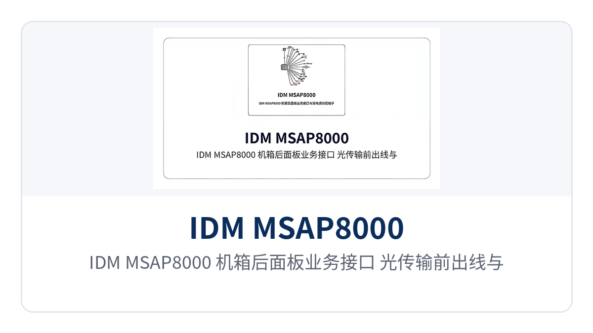
Figure 2: Layout of the service interfaces, front-cabled optical transmission interfaces, and dual power supply distribution terminals on the rear panel of the IDM MSAP8000 chassis
What practical value do the three differentiated capabilities bring?
The three capabilities correspond to three requirements often raised simultaneously in private network projects, and can be checked item by item against capability and value. The left side of the table shows the verifiable technical form, and the right side shows the actual benefits at the equipment room and O&M level, which can be used directly to check against tendering clauses and technical specifications during selection.
| Differentiated capability | Actual value to private network customers |
|---|---|
| 420 E1 channels | A single unit carries 420 E1 channels and 300 channels of 64K PCM service; one 7U unit replaces multiple narrowband multiplexing devices, reducing the number of cabinets and cables |
| 14 slots with mixed insertion | 64K voice, E1, 155M, 622M, 2.5G, 10G, and GE/FE boards are mixed in the same chassis; expansion only requires adding boards, while the chassis and backplane are retained |
| 160G cross-connect | Higher-order 160G and lower-order 20G cross-connect; backbone scheduling and edge service termination are completed in the same matrix, eliminating separately stacked cross-connect devices at each layer |
| Dual bus 1+1 | Dual bus design with 1+1 hot standby for boards and 1:N protection for tributary boards, plus MSP 1+1/1:1 on the network side, with automatic switchover when an active board fails |
The termination capacity of 420 E1 channels and 300 channels of 64K PCM allows the narrowband services of a substation or a station to be concentrated on one unit. The number of cabinets, the scale of patch panels, and the number of cables in the equipment room decrease accordingly, and network management scope, spare parts variety, and duty inspection items are also easier to standardize.
Typical Application Scenarios
The IDM MSAP8000 targets private network scenarios that require both transmission capacity and reliability, and is typically deployed at backbone nodes or aggregation equipment rooms. As a professional SDH equipment manufacturer, Raytrans provides SDH equipment products and product showcase packages around the SDH and MSTP technology systems. The following three scenarios are typical deployments of this equipment in private networks.
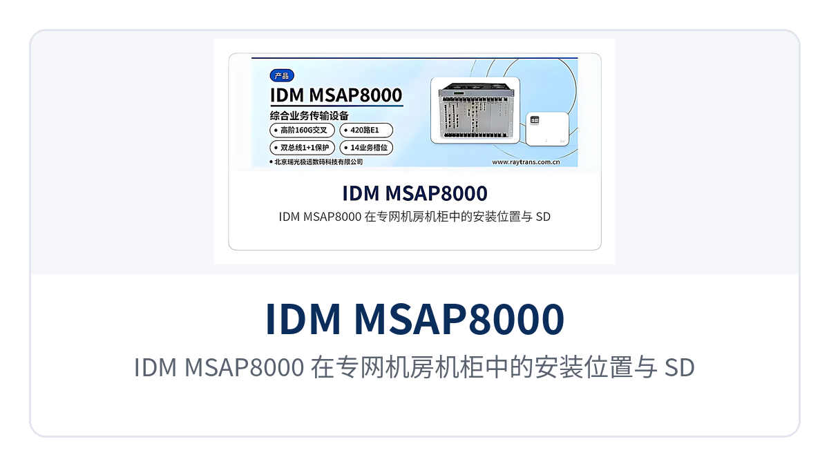
Figure 3: Installation position of the IDM MSAP8000 in a cabinet in a private network equipment room and schematic of SDH ring network connections
Electric Power Private Network
The dispatching data network and production channels of an electric power private network are sensitive to transmission interruption and usually require board-level redundancy and wide-range DC power supply. The IDM MSAP8000 meets this requirement with a dual bus design, 1+1 hot standby for critical boards, and 1:N protection for tributary boards, and its -48VDC power supply can be taken directly from the power distribution panel in the substation equipment room.
The 420 E1 channel access volume is aggregated by site and then concentrated onto the backbone, so distributed 2M circuits no longer require stacked equipment at every site. The number of cabinets and the maintenance workload in the substation equipment room are reduced accordingly, and when a new bay is put into operation, boards can simply be added as needed without replacing the entire unit or rebuilding the platform, preserving the continuity of the transmission platform.
Rail Transit Communication
The transmission network for rail transit communication must carry voice, circuit, and data services simultaneously within limited equipment rooms. The IDM MSAP8000 uses 14 service slots for mixed insertion of PCM voice boards, E1 boards, and GE/FE data boards, so that narrowband and data services on the station side are accessed into the same chassis at once.
Optical transmission interfaces are cabled at the front and service interfaces at the rear, and the front-installation, front-maintenance structure facilitates cabling and inspection in space-constrained station equipment rooms. When the line is extended and new stations are added, service boards are inserted as needed without rebuilding the transmission platform. This form is also a typical networking approach of Raytrans's rail transit communication solution, making it easy to unify equipment models across the entire line.
Military and Government Private Network
Military and government private networks prioritize continuous availability and rapid fault location. The IDM MSAP8000 supports pluggable SFP optical modules (LC connector), the ALS function, and online optical power detection at the optical port, so O&M personnel can determine which segment of the line is faulty without changing service configurations.
The dual bus and 1+1 hot standby of boards, together with MSP 1+1/1:1 network-level protection, reserve continuous transmission channels for command and dispatch services. When the device is installed in the rack of an emergency communications vehicle, the 7U chassis and front maintenance approach facilitate rapid commissioning and withdrawal, meeting the mobile deployment requirements of the military emergency communications vehicle solution and also facilitating short-term duty at field sites. The optical transmission equipment from Raytrans adopts the same form in the government private network optical fiber communication solution, meeting the transmission continuity requirements of government services.
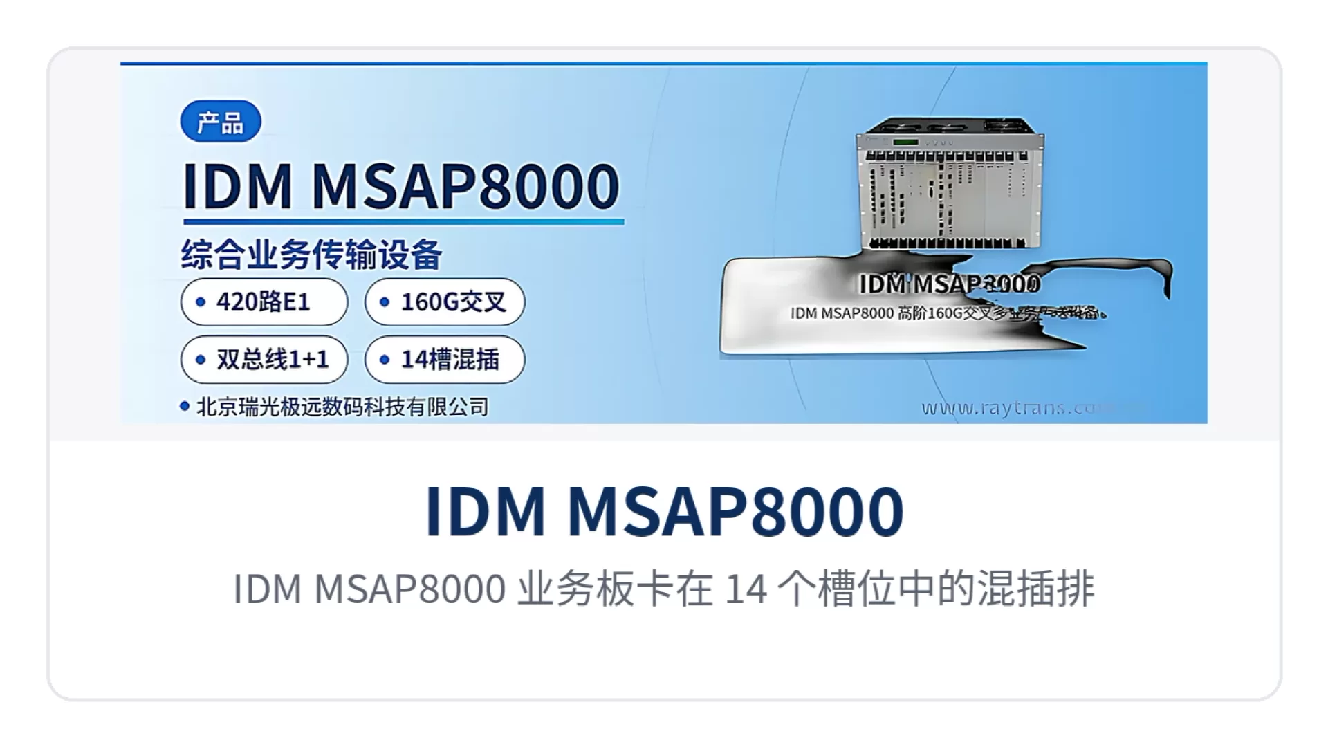
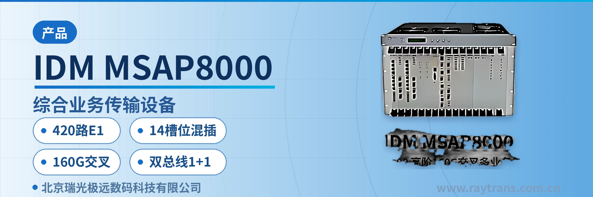
Figure 4: Close-up of the mixed insertion layout of IDM MSAP8000 service boards in 14 slots and the plugging or unplugging maintenance of SFP optical modules