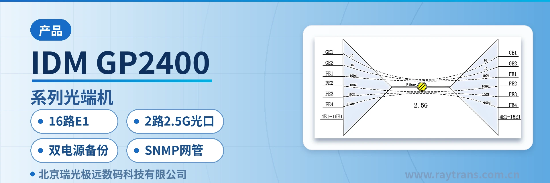
IDM GP2400 Series PDH Optical Multiplexer
16 × E1, 4 × Fast Ethernet, 2 × Gigabit Ethernet single-fiber aggregation, one unit replaces three, saving switches at the site
The IDM GP2400 series optical multiplexer provides 2.5G optical ports, 4 to 16 groups of E1 circuits, 4 groups of line-rate 100M Ethernet, and 2 groups of line-rate 1000M Ethernet interfaces. It can provide an SNMP network management interface, comprehensive alarm monitoring, high integration, low power consumption, stable performance, and ease of use. It can be widely used in private networks such as public security, electric power, railway, and mining, as well as in public networks of carriers such as China Mobile, China Unicom, and China Telecom.
The IDM GP2400 series optical multiplexer is a PDH optical multiplexer developed by Beijing Ruiguang Jiyuan Digital Technology Co., Ltd. It transmits E1 circuits and Fast Ethernet and gigabit Ethernet services simultaneously over a pair of optical fibers, and a standalone unit provides 2 2.5G optical ports, 4 to 16 groups of E1, 4 Fast Ethernet ports, and 2 gigabit Ethernet interfaces. As a typical multi-service optical multiplexer, the device uses a 19-inch 1U chassis and supports SNMP network management and dual power supply backup.
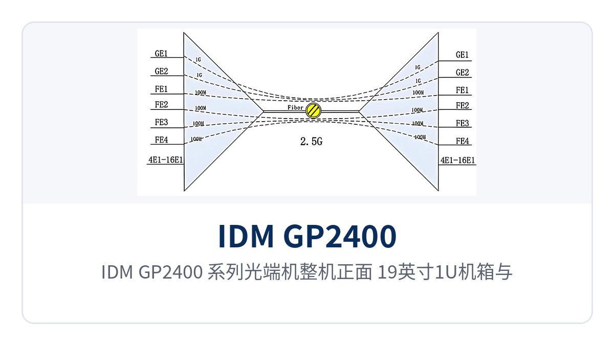
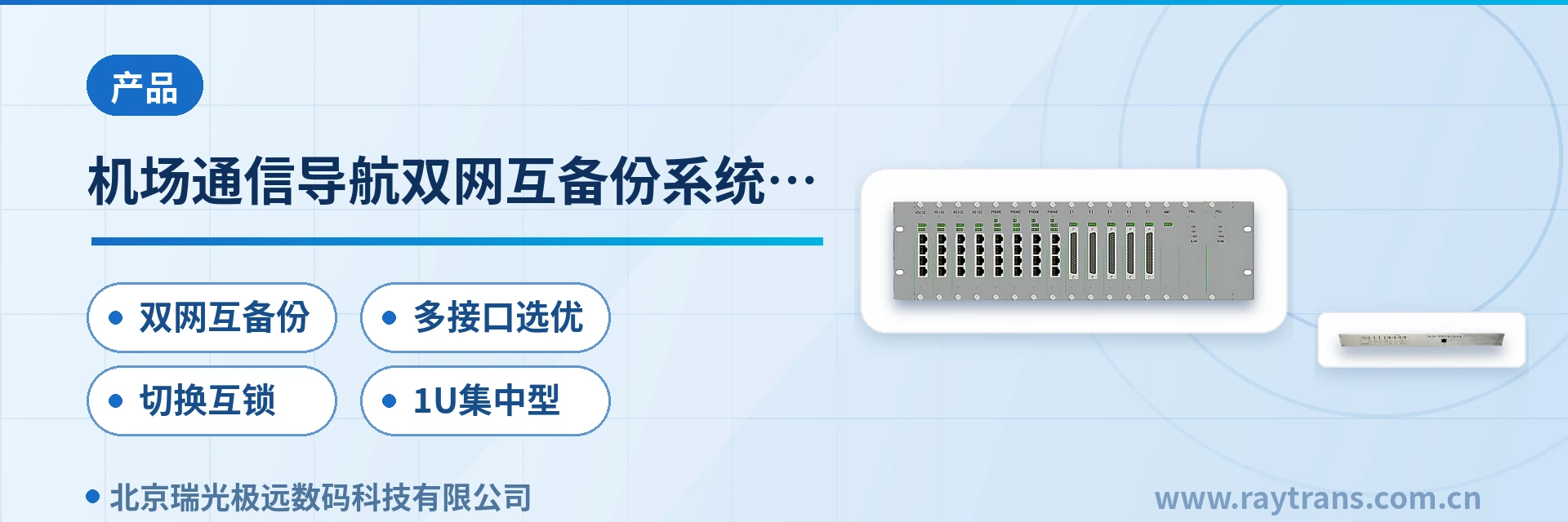
Figure 1: Front view of the IDM GP2400 series optical multiplexer, 19-inch 1U chassis and front-panel alarm indicator LEDs
For integrated access between sites on private networks such as public security, electric power, railway, and mining, a standalone unit packs 16 E1 channels, 4 Fast Ethernet ports, and 2 gigabit Ethernet ports into one 1U device. This is the direct value that distinguishes the IDM GP2400 series PDH optical multiplexer from single-service optical multiplexers, and it also reflects how a professional optical multiplexer manufacturer considers multi-service convergence capability in its product showcase. In the past, a private network site had to be equipped separately with an E1 multiplexer, a switch, and gigabit transmission equipment; now one device can complete the access and aggregation of three types of services, reducing rack space and associated cabling at the same time. Whether for a government private network optical fiber communication solution, a smart mining communication solution, or a military emergency communications vehicle solution, this type of gigabit network optical multiplexer and multi-service optical multiplexer can serve as the core access device at the site; Raytrans can also provide corresponding product showcase and selection support around actual networking requirements.
Key specifications at a glance: 2 2.5G SFP optical ports (standard transmission 40 km) · 4 to 16 groups of E1 (ITU-T G.703, 75 Ω/120 Ω) · 4 Fast Ethernet + 2 gigabit Ethernet · dual power supply backup (AC220V/DC-48V) · 19-inch 1U chassis 482×309×132 mm
What kind of device is the IDM GP2400 series optical multiplexer
The IDM GP2400 series optical multiplexer is a PDH optical multiplexer device that multiplexes narrowband E1 services and broadband Ethernet services onto the same 2.5Gbps optical fiber link. One unit is placed at each end of the link: one end aggregates the services and feeds them into the fiber, and the other end restores them to standard interfaces for output. All service-side interfaces connect according to common standards, so existing SPC switching equipment, routers, or monitoring platforms can be accessed without changing their original configuration, and the amount of site modification is small. It is one of the product showcase models that the optical multiplexer manufacturer Raytrans offers for the private network market.
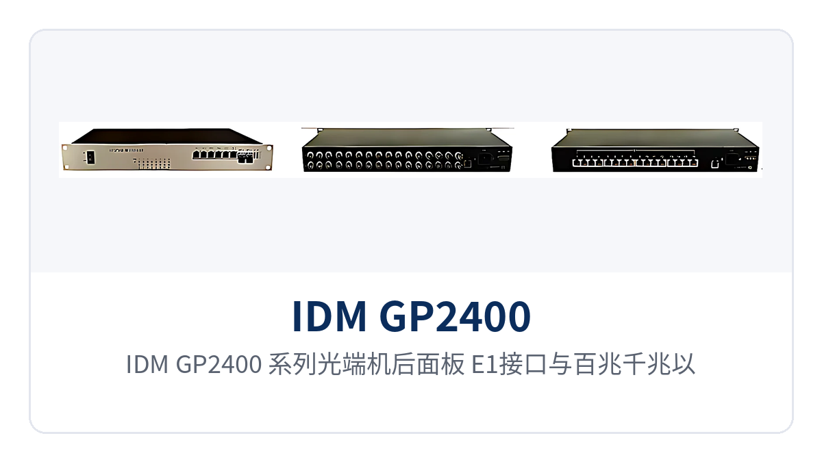
Figure 2: Rear panel of the IDM GP2400 series optical multiplexer, layout of E1 interfaces and Fast/gigabit Ethernet ports
How three types of services are transmitted in parallel over a pair of optical fibers
E1 channels are organized according to the PCM30/32 frame structure, with a bit rate of 2.048Mbps and HDB3 line code, compliant with the ITU-T G.703 standard; in transparent transmission mode, the time slot content is not modified. Ethernet channels are encapsulated according to IEEE802.3, with 10M/100M/1000M auto-negotiation and full/half duplex auto-negotiation; after entering the 2.5G optical port, they are multiplexed with fixed bandwidth allocation, and the two types of services do not preempt each other's capacity.
The 2 gigabit Ethernet ports are physically isolated from each other, and the bandwidth of each group can be set separately, so monitoring, office, and service data can be carried on separate ports without affecting each other; the 4 Fast Ethernet ports are used to connect low-speed services such as cameras and terminals. This interface division allows one 2.5G multi-service optical multiplexer to take on both service isolation and centralized backhaul, so the site side no longer needs an external switch; the capability of the gigabit network optical multiplexer is fully demonstrated here.
Core functions and interface configuration
The functions of the IDM GP2400 series optical multiplexer are designed around three main lines: E1 transparent transmission, Ethernet aggregation, and centralized monitoring. The interface form and on-site role corresponding to each function item are summarized in the table below; check row by row according to service type to determine the wiring method.
| Function | Description |
|---|---|
| 19-inch 1U chassis structure | Uses a standard 19-inch 1U chassis that can be installed directly in a private network cabinet, with little equipment room renovation |
| 2 2.5G SFP optical ports | Provides 2 SFP optical module slots, receive/transmit rate 2.5G/5.25G, single-mode fiber with multimode optional |
| 4 to 16 groups of E1 circuits | E1 bit rate 2.048Mbps, HDB3 line code, 75 Ω or 120 Ω impedance selectable, supports transparent transmission |
| 2 gigabit Ethernet ports | 2 physically isolated 1000M interfaces, each group's bandwidth configurable, can carry monitoring and service data on separate ports |
| 4 Fast Ethernet ports | 4 100M line-rate Ethernet interfaces for access of low-speed services such as cameras and terminals |
| SNMP network management interface | Provides an IP-based SNMP network management interface, supporting centralized configuration and alarm viewing |
| Alarm monitoring function | Two levels of alarms, panel indicator LEDs and network management, for locating abnormalities on site and remotely at the same time |
| Dual power supply backup | Supports AC220V and DC-48V, with optional DC+DC, AC+AC, AC+DC dual backup power supply |
Technical specifications and interface specifications
The following parameters cover optical interfaces, E1 interfaces, Ethernet interfaces, and power supply and environmental conditions. The values are taken from the IDM GP2400 series optical multiplexer product documentation for networking design and equipment selection verification. Where on-site conditions differ from commercial terms, the manufacturer's technical documentation and commercial confirmation shall prevail.
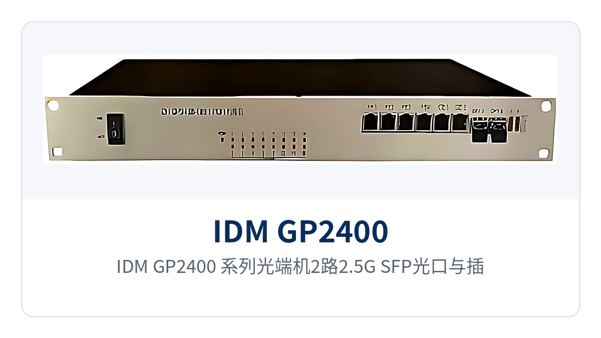
Figure 3: Close-up of the 2 2.5G SFP optical ports and inserted optical modules of the IDM GP2400 series optical multiplexer
| Item | Parameter/Specification | Description/Applicable Conditions |
|---|---|---|
| Optical interface type | SFP | Pluggable optical module, selected according to distance and fiber core conditions |
| Fiber mode | Single-mode (multimode optional) | Multimode is used for short-distance interconnection within an equipment room |
| Receive/transmit rate | 2.5G/5.25G | The 2 2.5G optical ports operate at this rate |
| Receive/transmit wavelength | 1310nm/1550nm | Two wavelengths selectable, used in pairs at both ends |
| Transmit optical power | +2dBm | Typical value for single-mode modules, subject to actual measurement with an optical power meter |
| Receiver sensitivity | Better than -20dBm | The link loss budget can be calculated on this basis |
| Transmission distance | 40 km for standard models | Repeaterless transmission; long-distance optical modules can be customized if exceeded |
| Number of E1 interfaces | 4/8/16 groups | Selected according to model suffix, fixed configuration at the factory |
| E1 bit rate and line code | 2.048Mbps / HDB3 | Compliant with ITU-T G.703 |
| E1 impedance | 75 Ω/120 Ω | Selectable, matching the interface of the connected device |
| E1 frame structure and signaling | PCM30/32 / channel-associated signaling (CAS) | Time slot content is not changed during transparent transmission |
| Ethernet interfaces | 2 gigabit + 4 Fast Ethernet, RJ45 | 10M/100M/1000M auto-negotiation, compliant with IEEE802.3 |
| Ethernet operating mode | Full/half duplex/adaptive | Auto-negotiation with the peer device |
| Power supply mode | AC220V/DC-48V | Optional DC+DC, AC+AC, AC+DC dual backup |
| Overall power consumption | ≤90W | Unit value including optical modules |
| Operating temperature | -10℃~+50℃ | Suitable for unattended equipment room environments |
| Relative humidity | 0~95% (non-condensing) | No condensation inside the cabinet |
| Product dimensions | 482×309×132 mm | 19-inch 1U chassis, including mounting ears |
What on-site problems do 16 E1 channels and 2 2.5G optical ports in a standalone unit solve
Access requirements at private network sites usually focus on three points: many types of narrowband services but small capacity at a single point, limited optical fiber resources, and equipment rooms that are mostly unattended. As a multi-service optical multiplexer, the IDM GP2400 series optical multiplexer addresses these three points through its interface density, optical port specifications, and power supply design, merging functions previously handled by multiple devices into one 1U chassis and flexibly adapting to typical scenarios such as government private network optical fiber communication solutions, smart mining communication solutions, and military emergency communications vehicle solutions.
| Differentiated capability | Value to private network sites |
|---|---|
| 16 E1 + 4 Fast Ethernet + 2 gigabit in a standalone unit | One device completes narrowband and broadband service access, saving space in private network equipment rooms and reducing cabinet and cabling costs at the same time |
| 2 2.5G SFP optical ports, standard transmission 40 km | Meets long-distance private network networking; long-distance optical modules can be customized when the distance exceeds that of standard models |
| AC/DC dual backup power supply optional | AC and DC can be connected at the same time, so services continue to run when a single power supply fails |
| -10℃~+50℃ wide-temperature design | Suitable for unattended equipment rooms without air conditioning and field sites |
| SNMP network management and alarm monitoring | The duty room can view site status centrally, reducing on-site inspection frequency |
Typical application scenarios
Public security private network: E1 leased line and monitoring data backhaul from police station to sub-bureau
Between a police station and a sub-bureau, it is necessary both to transmit the E1 leased line channel of the public security intranet and to backhaul the video surveillance data within the station. Deploy one IDM GP2400 series PDH optical multiplexer at each end, use 4 groups of E1 to carry leased-line services and 2 gigabit ports to carry monitoring and office data on separate ports, and a pair of optical fibers completes the product showcase and service backhaul. With the gigabit ports physically isolated, increased monitoring traffic will not squeeze the bandwidth of office services.
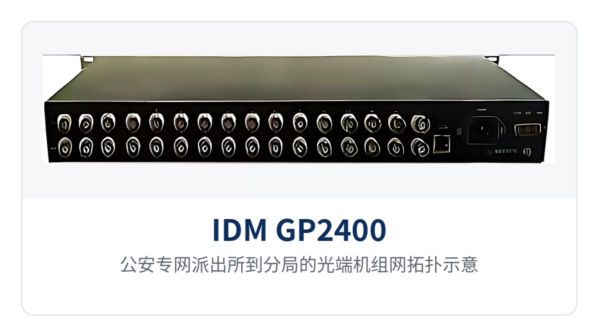
Figure 4: Networking topology diagram of optical multiplexers from police station to sub-bureau on the public security private network
Electric power private network: substation dispatch channels and in-station data backhaul over the same fiber
Between a substation and a dispatch center, E1 channels such as telecontrol and protection signals and in-station Ethernet data are usually transmitted in parallel. The IDM GP2400 series multi-service optical multiplexer aggregates 8 to 16 groups of E1 and 4 Fast Ethernet ports onto a pair of optical fibers, so only one 1U rack position needs to be reserved in the station. The device supports AC220V and DC-48V dual power supply access, so the station DC distribution panel and AC mains power can be introduced at the same time, keeping the power supply mode consistent with existing conditions in the station.
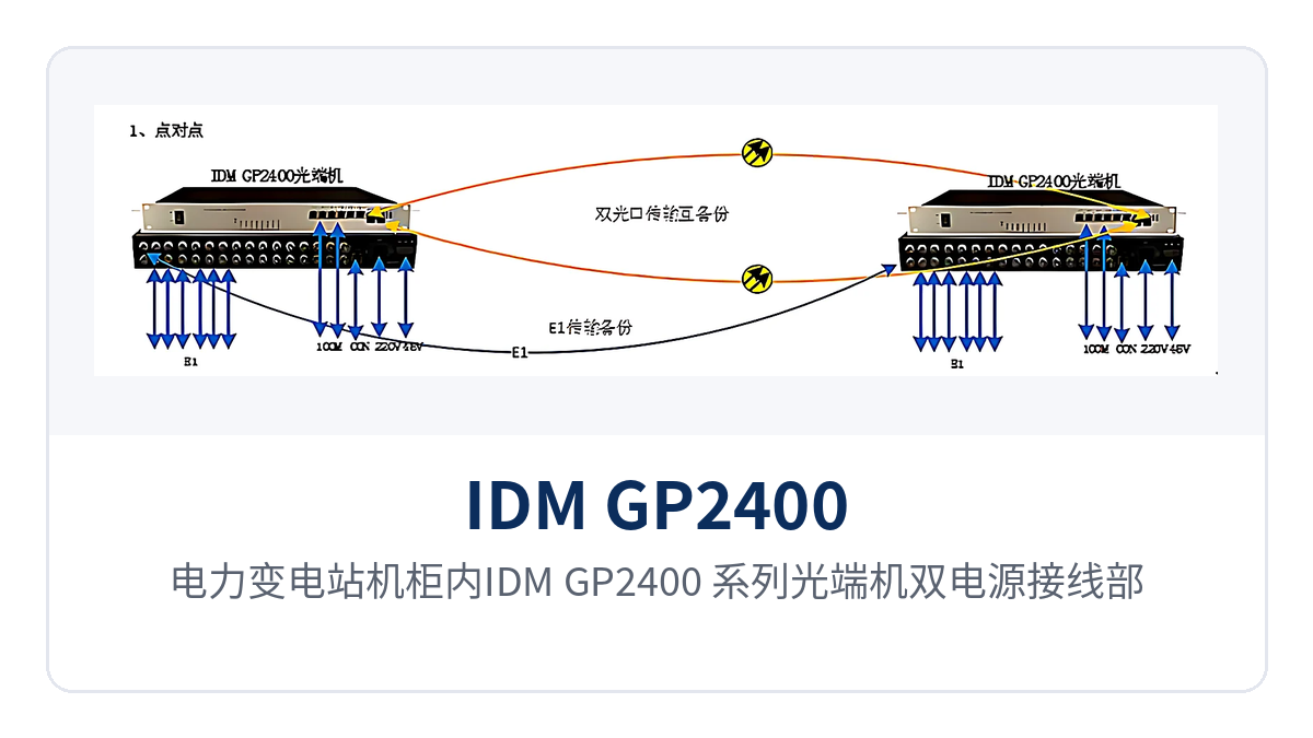
Figure 5: Dual power supply wiring deployment of the IDM GP2400 series optical multiplexer in an electric power substation cabinet
Railway private network: channel and video access between stations and trackside sites
Trackside sites along a railway are scattered and equipment room conditions vary greatly, and trackside sites are often unattended. The IDM GP2400 series optical multiplexer adapts to such environments with an operating temperature of -10℃~+50℃ and dual power supply backup; 16 groups of E1 can carry signal and service channels, and the 2 gigabit ports connect video and service data separately, so the site side no longer stacks multiple small devices.
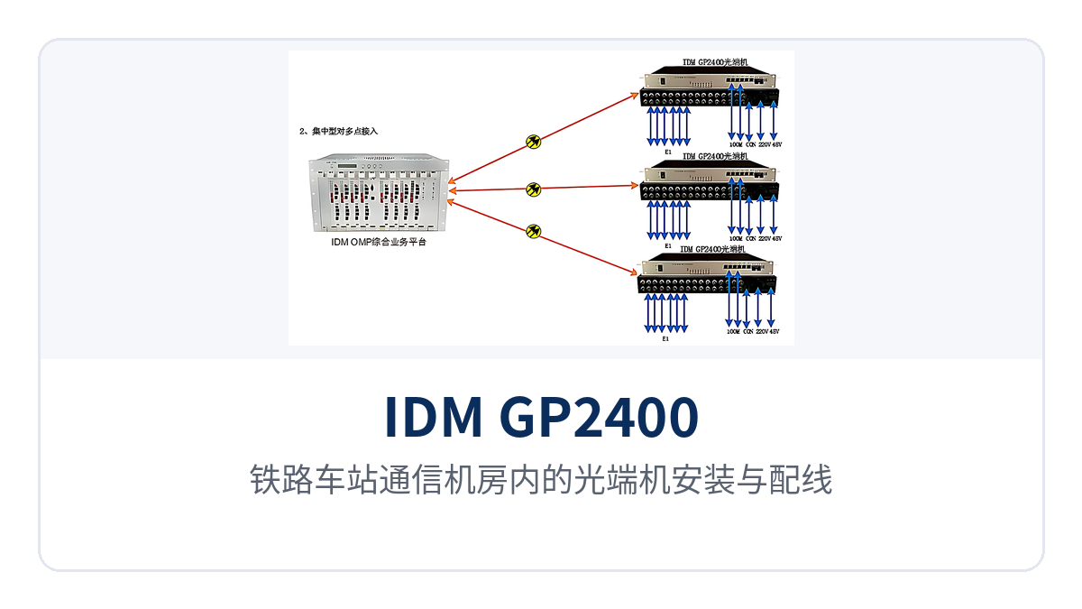
Figure 6: Installation and wiring of optical multiplexers in a railway station communications equipment room
Mining and carriers: multi-service aggregation at pithead sites and access nodes
Sites such as mine pitheads and ventilation shafts, as well as carrier access nodes, concentrate multiple services in one cabinet, which is exactly a typical application point of the smart mining communication solution. The IDM GP2400 series gigabit network optical multiplexer packs E1 channels, Fast Ethernet monitoring, and gigabit uplink into 1U of space, so it can be deployed even when equipment room space is tight; SNMP network management lets the duty room view alarms from all sites in one place without inspecting each site one by one.
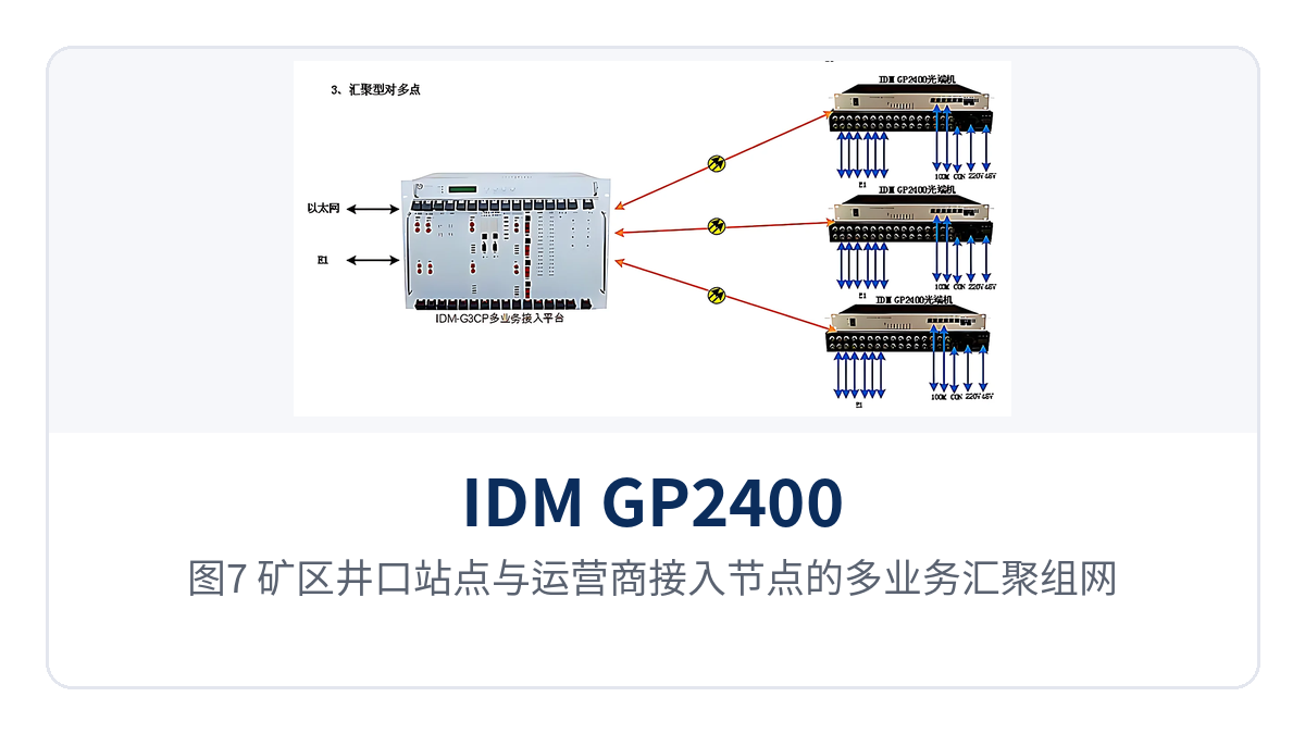
Figure 7: Multi-service aggregation networking of a mine pithead site and a carrier access node
How to Choose Between 4E1, 8E1 and 16E1
The key to selection is to count how many E1 groups the site needs, then confirm whether the Ethernet ports are sufficient. The three models in the GP2400 series have identical optical port and Ethernet configurations; they differ only in the number of E1 interfaces. Simply reserve two to four groups of margin based on the number of E1 channels on site, and there is no need to move up to a high-capacity model in advance for future capacity expansion.
| Model | E1 interface | Ethernet interface | Applicable sites |
|---|---|---|---|
| IDM GP2400 4E1 | 4 groups | 4-channel 100M + 2-channel 1000M | End sites with low E1 demand and mainly data backhaul |
| IDM GP2400 8E1 | 8 groups | 4-channel 100M + 2-channel 1000M | Medium sites balancing dedicated line channels and data backhaul |
| IDM GP2400 16E1 | 16 groups | 4-channel 100M + 2-channel 1000M | Branch bureaus, substations and stations with concentrated E1 channels |
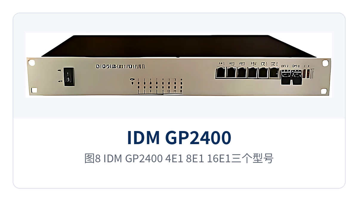
Figure 8: Front panel interface comparison of the IDM GP2400 4E1, 8E1 and 16E1 models
Installation and Commissioning Highlights
The IDM GP2400 series optical multiplexers use a standard 19-inch 1U chassis, and installation and commissioning proceed more smoothly in the following order. Each step corresponds to an item that can be checked on site; confirming each item before connecting services reduces rework and secondary downtime.
- Cabinet positioning: confirm the 1U rack position, intake and exhaust clearance and grounding; the unit dimensions are 482×309×132mm
- Optical fiber connection: pair by SFP module wavelength, use 1310nm and 1550nm in pairs, and cross-connect receive and transmit
- E1 wiring: select 75Ω or 120Ω impedance according to the interconnected equipment, and keep the impedance consistent at both ends of the same E1 link
- Ethernet access: connect the Gigabit ports by service, and set the respective bandwidth of the 2 Gigabit ports in the network management system
- Power supply access: connect AC220V and DC-48V according to on-site conditions; for dual-backup models, power on both power feeds at the same time
- Network management configuration: after assigning an IP address, connect to SNMP network management and confirm that alarm reporting is consistent with the panel indication
How to Use SNMP Network Management and Alarm Monitoring
After the services are connected, configure an IP address for the IDM GP2400 series optical multiplexer and add it to SNMP network management, and site status can then be viewed in the duty room. Alarms such as no optical signal received at the optical port, E1 channel loss and power supply abnormality can be reported to the NMS platform, and the panel indicator LEDs change accordingly, so the remote end and the site match, and troubleshooting no longer requires visiting each site.
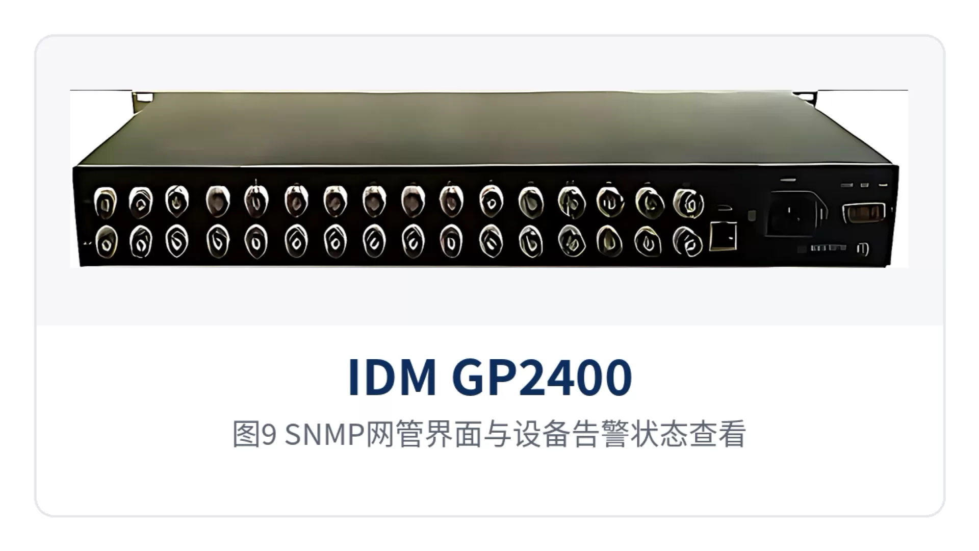
Figure 9: SNMP network management interface and device alarm state viewing