IDM GP2000 Dual Gigabit Ethernet Optical Multiplexer
2.5G self-healing ring network, dual gigabit, dual RS485, multiple serial ports aggregated into one IP port
The IDM GP2000 dual gigabit Ethernet optical multiplexer uses 2.5G optical fiber ring networking. The central-end equipment uses our IDM MSAP-G3CP as the aggregation node to provide the gigabit Ethernet and RS485 services from remote GP2000 devices. The remote node uses our IDM GP2000 device, which directly provides 2 physical gigabit Ethernet ports and 2 RS485 service interfaces. This solution can be widely used in security surveillance, expressway surveillance, tunnel network transmission and other systems, providing high-speed gigabit Ethernet services and RS485 serial port data.
IDM GP2000 dual gigabit Ethernet optical multiplexer is a 2.5G optical fiber ring network transmission device for video surveillance and serial port data backhaul, developed by optical multiplexer manufacturer Beijing Ruiguang Jiyuan Digital Technology Co., Ltd. (Raytrans), and used to deliver gigabit Ethernet and RS485 services from remote stations to the central end over optical fiber. A single remote node provides 2 physical gigabit Ethernet ports and 2 RS485 interfaces, while the central end uses the IDM MSAP-G3CP centralized plug-in card equipment as the aggregation node. In the media converter product showcase, the unit belongs to the gigabit network optical multiplexer category for industry networking.
The pain point of surveillance projects lies in the link itself: once toll stations, tunnels and sites along a road section are chained together, any optical cable that is dug up will cut off all the sites behind it. This dual gigabit Ethernet optical multiplexer supports chain network and ring network topologies. Once the ring is formed, an optical cable interruption at one point makes services automatically switch to the other side of the ring, so sites do not have to stop services and wait for emergency repair. This makes it particularly suitable for security surveillance services with high requirements on link continuity in expressway surveillance and tunnel network transmission scenarios.
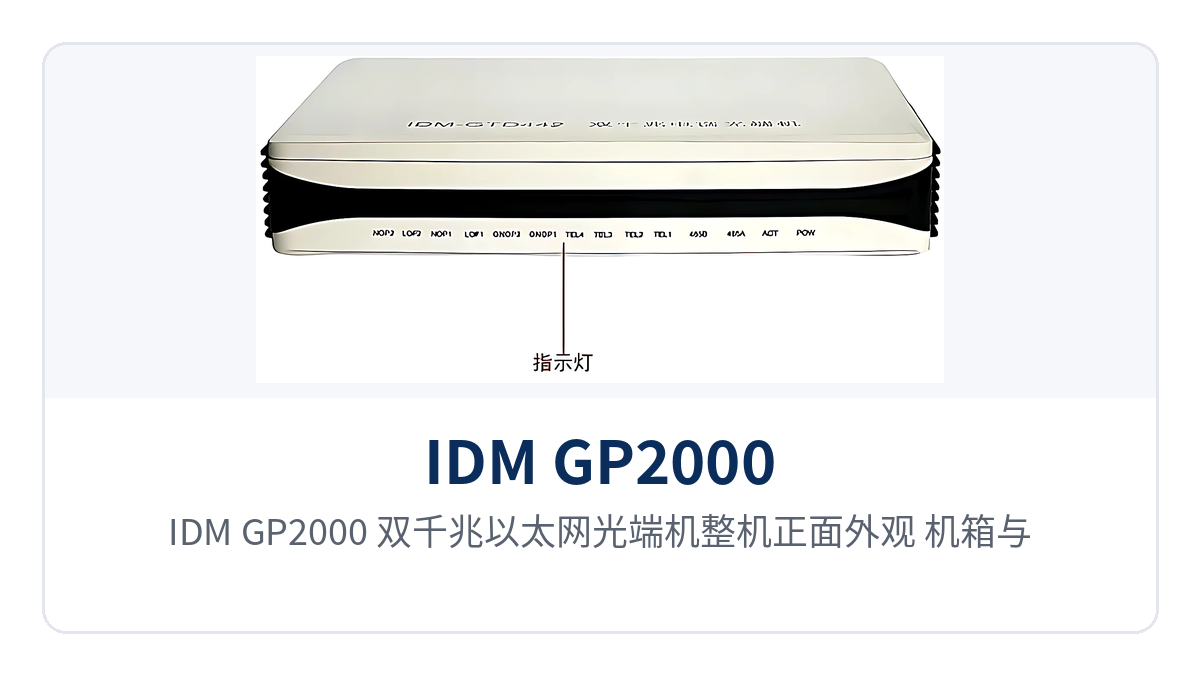
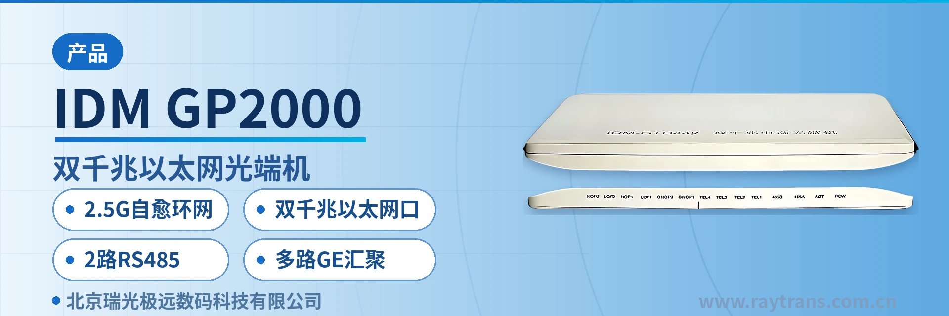
Figure 1: Front appearance of the IDM GP2000 dual gigabit Ethernet optical multiplexer, showing the enclosure and panel indicator LEDs
Key specifications at a glance: 2.5G self-healing ring network (chain network and ring network) · dual gigabit Ethernet ports · 2-channel RS485 · multi-channel GE aggregation · multi-channel RS485 aggregated into one IP port · central end IDM MSAP-G3CP. As part of the multi-service optical multiplexer and video optical multiplexer product lines, Raytrans provides complete optical multiplexer product showcase and selection support.
What kind of device is a dual gigabit Ethernet optical multiplexer
A dual gigabit Ethernet optical multiplexer, also commonly called a gigabit ring network optical multiplexer, is a device that multiplexes gigabit Ethernet and RS485 serial port data onto optical fiber for transmission. When organized as a ring network, it can be connected site by site along the line and closed head-to-tail into a ring. As part of the media converter product category, the IDM GP2000 acts as the remote access node in this structure, while the central side uses the IDM MSAP-G3CP for aggregation. The two are interconnected over a 2.5G optical link, forming a path of remote access plus central aggregation.
How a 2.5G self-healing ring network keeps services alive when an optical cable is interrupted
Ring network self-healing requires that every site has two optical directions: one along the line to the next station and one to the previous station, with both ends returning to the central end. The 2.5G optical link brings the Ethernet and RS485 services of each station into the ring. Normally, services are sent to the center in one direction; when a section of the ring is interrupted, services are rerouted inside the device in the other direction and no longer pass through the failed section.
The change in networking approach also simplifies cable construction. Only optical cable needs to be laid along the line between sites, and video and serial port data share one optical fiber link, so no separate copper cable is needed for each service type. The number of connectors, cable tray occupancy and points of failure are reduced accordingly, and power supply access and enclosure conditions along the line are more uniform.
What service interfaces does the remote node provide
The remote node is the end installed on site, and its service-side interfaces determine how cameras and serial port devices are connected. The IDM GP2000 uses a fixed configuration for its interfaces, so wiring is done directly by interface type during commissioning without additional converters or expansion modules. This means fewer devices in the site enclosure and simpler O&M inventory checks.
What the 2 physical gigabit Ethernet ports connect to
The 2 gigabit Ethernet ports are independent physical interfaces that can connect to network cameras, NVRs, switches or roadside devices separately. A common practice in video surveillance is to use one port for the video ring network and the other for the toll or office network, so the two service types each use their own port and do not share the same forwarding channel. The interface rate is gigabit and backward compatible with Fast Ethernet terminals.
What the 2-channel RS485 connects to
The 2-channel RS485 carries serial port data, typically for PTZ control, vehicle detectors, variable message signs, tunnel environment monitoring and lighting control devices. RS485 is a two-wire differential bus, connected on the site side in A/B wiring sequence. When multiple slave devices are attached to the same bus, they are distinguished by address, and serial port data and video are backhauled over the same optical link.
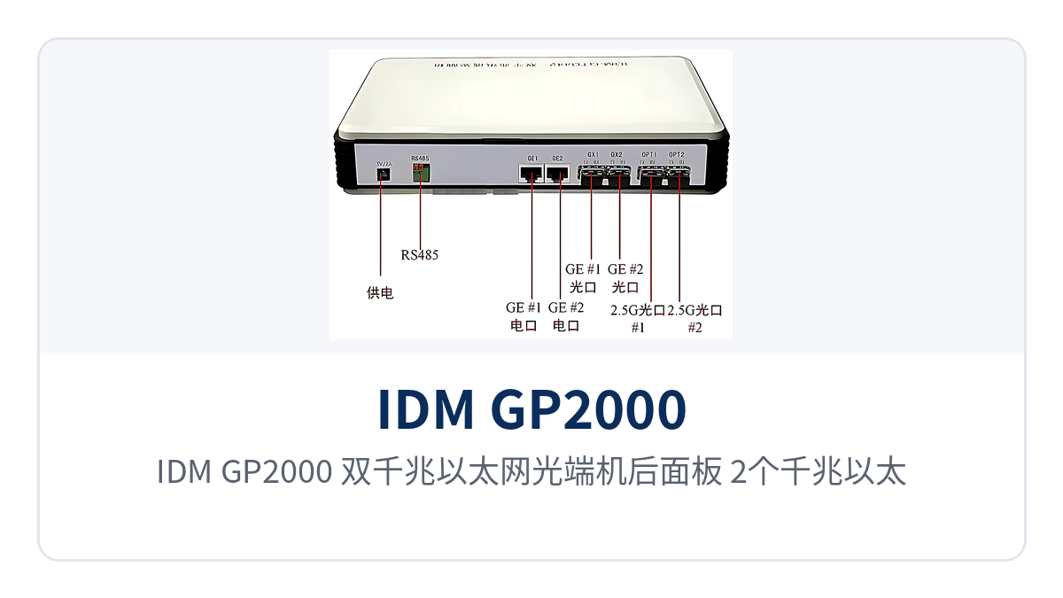
Figure 2: Rear panel of the IDM GP2000 dual gigabit Ethernet optical multiplexer, showing the layout of 2 gigabit Ethernet ports and 2 RS485 interfaces
How the central end aggregates multiple RS485 channels into one IP port
The IDM MSAP-G3CP at the central end is centralized plug-in card equipment where services from multiple remote stations are terminated and output to the upper-level platform. After multiple RS485 services are aggregated into one IP port at the central end, the monitoring platform only needs to connect to one network port and access one IP address to poll the serial port devices of each site along the line, without opening a separate serial port server for each site.
The gigabit Ethernet side is also aggregated at the central end. Video streams uploaded from each site enter the core network uniformly from the aggregation side, and the platform only needs to plan channels by site number. Aggregation-side bandwidth is calculated according to the number of sites and total stream volume. For capacity expansion, adding remote nodes is enough to provide access, reserving access means for later security surveillance and emergency communications.
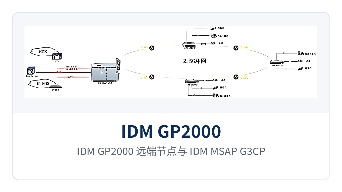
Figure 3: Topology schematic of a 2.5G self-healing ring network formed by IDM GP2000 remote nodes and an IDM MSAP-G3CP central aggregation node
Functions and performance specifications
The following table lists remote interfaces, ring network capabilities and central aggregation item by item, making it easy to check the configuration against the site service list. The parameters are taken from IDM GP2000 product documentation; items not given in the documentation are noted in the table, and the specific configuration should be confirmed with the optical multiplexer manufacturer before ordering.
| Function | Description |
|---|---|
| 2.5G optical fiber ring network | Remote and central ends are networked over a 2.5G optical link, supporting chain network and ring network; when an optical cable is interrupted at one point on the ring, services self-heal and reroute |
| 2 physical gigabit Ethernet ports | A single remote unit provides 2 physical gigabit Ethernet interfaces, which can carry video surveillance and office or toll data separately |
| 2-channel RS485 service interface | A single remote unit provides 2-channel RS485, carrying serial port data such as PTZ control, vehicle detectors and variable message signs |
| Multiple RS485 channels aggregated into one IP port | The central end aggregates multiple RS485 services into one IP port, and the platform accesses serial port devices along the line via a single IP address |
| Multi-channel gigabit Ethernet aggregation | The central end aggregates gigabit Ethernet services from multiple remote sites and sends them to the core network |
| Chain network and ring network | Supports chain connection and head-to-tail ring formation; sites choose the topology according to the line route, simplifying cable construction |
| Reserved capacity for expansion | Capacity can be expanded by adding remote nodes as required, providing access means for later security surveillance and emergency communications |
| Item | Parameter/Specification | Description/Applicable Conditions |
|---|---|---|
| Optical fiber transmission rate | 2.5G | The same rate is shared by ring network and chain network |
| Networking approach | Chain network, ring network (self-healing) | A ring network requires both ends to return to the central end |
| Remote Ethernet interface | 2 physical gigabit Ethernet ports | RJ45 connector, backward compatible with Fast Ethernet terminals |
| Remote serial port interface | 2-channel RS485 | Two-wire differential bus, connected in A/B wiring sequence |
| Central-end aggregation equipment | IDM MSAP-G3CP | Centralized plug-in card equipment, handling multi-channel GE and RS485 aggregation |
| Central-end serial port output | Multiple RS485 channels aggregated into one IP port | The platform accesses the serial port devices of each site via a single IP address |
| Service types carried | Gigabit Ethernet, RS485 serial port data | Video and serial port data are backhauled over the same cable |
| Optical interface type and transmission distance | not yet recorded in the knowledge base | According to line length and optical module configuration; confirm with the manufacturer before ordering |
| Power supply mode | not yet recorded in the knowledge base | Subject to the supplied technical documentation and site power supply access conditions |
| Operating temperature and installation method | not yet recorded in the knowledge base | Confirm according to protection and temperature control conditions for outdoor enclosures |
Typical application scenarios
Video surveillance projects share common traits: sites are distributed along the line, the service volume at a single point is not large, but the link must not be interrupted. The following three scenarios are common applications of the dual gigabit Ethernet optical multiplexer. The networking topology, interface allocation and central aggregation approach are determined according to on-site conditions, and sites can be added or removed on the ring at any time.
Security surveillance: monitoring points backhauled over an optical fiber ring
Monitoring points on urban roads and industrial park perimeters are scattered, and leasing a link for each point is costly. One remote node is placed in each surveillance box, with the 2 gigabit ports connected to the camera and the local switch respectively. Multiple sites are chained along the optical fiber into a ring back to the surveillance center, where the IDM MSAP-G3CP aggregates the video streams from each site and sends them to the platform.
Once the ring is formed, if an optical cable is dug up during construction, video streams switch to the other side, and the surveillance center does not lose all images due to a single point of failure. In this scenario, the RS485 channel often connects to speed dome PTZ and alarm linkage devices. Serial port control and video use the same optical fiber, so no serial port server needs to be placed in the front-end box.
Expressway surveillance: one unit from toll station to road section center
Expressway surveillance is organized into toll stations, road section sub-centers and tunnel portals. Distances between stations are long, and cabinet and power supply access conditions are limited. Remote nodes are deployed by site: one gigabit port connects to lane license plate recognition and video, the other to the station office network, and the 2-channel RS485 connects to lane controllers and variable message signs, with services backhauled to the road section center along the road section optical cable.
The central aggregation node concentrates the gigabit services of each toll station and sends them to the road section monitoring platform. Multiple RS485 channels are aggregated into one IP port, and the platform polls lane devices along the line via one address. From toll station to road section center, only one set of equipment and one optical link are needed, and existing cameras and lane controllers can continue to be used during upgrades.
Tunnel network transmission: services continue when an optical cable is unexpectedly interrupted
In tunnels, surveillance, lighting control, variable message signs and vehicle detectors are distributed along the tunnel bore. Equipment spacing is short but the quantity is large, and both power supply and maintenance windows are limited. Remote nodes are installed at tunnel portals and in equipment boxes inside the tunnel, with gigabit ports connected to cameras and switches and RS485 ports connected to lighting control and detection devices. Services are chained along the in-tunnel optical cable back to the tunnel management station.
In-tunnel optical cables are often interrupted by construction, fire or vehicle accidents, and ring network self-healing is designed for exactly such failures: services switch to the other side of the ring on both sides of the breakpoint, and lighting control and video do not stop with the breakpoint. During construction, only one optical cable needs to be laid along the tunnel bore, reducing copper cable usage and the number of connectors. When adding sites later, new remote nodes can simply be connected to the ring.
Networking and deployment points
On-site implementation proceeds in four steps: first determine the topology, then check interfaces and wiring sequence, then check the optical link and power supply access, and finally check central-end aggregation and platform access. Confirming all four steps at the drawing stage means wiring can follow the drawings during commissioning, significantly reducing rework and second site visits.
- Topology selection: if sites are distributed in a band along the line and both ends can return to the center, choose a ring network; if endpoint sites cannot form a ring, choose a chain network, and services at the endpoints are not protected by ring network protection.
- Interface allocation: allocate the 2 gigabit ports by service, connecting video separately from office and toll networks, so the two service types do not compete for the same forwarding channel.
- RS485 wiring sequence: connect in A/B wiring sequence, configure bus termination at both ends according to on-site conditions, and use uniform wiring sequence labels on the site side for easier later troubleshooting.
- Optical link calculation: select optical modules according to line length, count splice points and patch cords in link loss, and confirm module specifications with the optical multiplexer manufacturer before ordering for long-distance sections.
- Power supply access and installation: determine the power supply and installation method according to site enclosure conditions, apply waterproofing and temperature control to outdoor enclosures, and take electrical parameters from the supplied technical documentation.
- Central-end access: check aggregation ports and platform-side IP planning according to the number of sites, and align the IP port for RS485 aggregation with the monitoring platform network segment in advance.
Conclusion
The dual gigabit Ethernet optical multiplexer carries remote gigabit Ethernet and RS485 services over a 2.5G optical fiber ring network. A single remote unit provides 2 physical gigabit ports and 2-channel RS485, while the central end uses the IDM MSAP-G3CP to complete multi-channel GE aggregation and aggregate multiple RS485 channels into one IP port. The link structure and interface configuration are defined once according to the site list. As an optical multiplexer manufacturer, Raytrans covers video optical multiplexers, gigabit network optical multiplexers, multi-service optical multiplexers and other categories in its media converter and optical multiplexer product showcase, making selection by scenario easier.
Link reliability is provided by ring network self-healing; the number of interfaces and the aggregation mode are determined by site service volume. The three scenarios of security surveillance, expressway monitoring, and tunnel network transmission can be implemented with the same structure. For capacity expansion, simply add remote end nodes to the ring; the central end structure does not need to be rebuilt.