
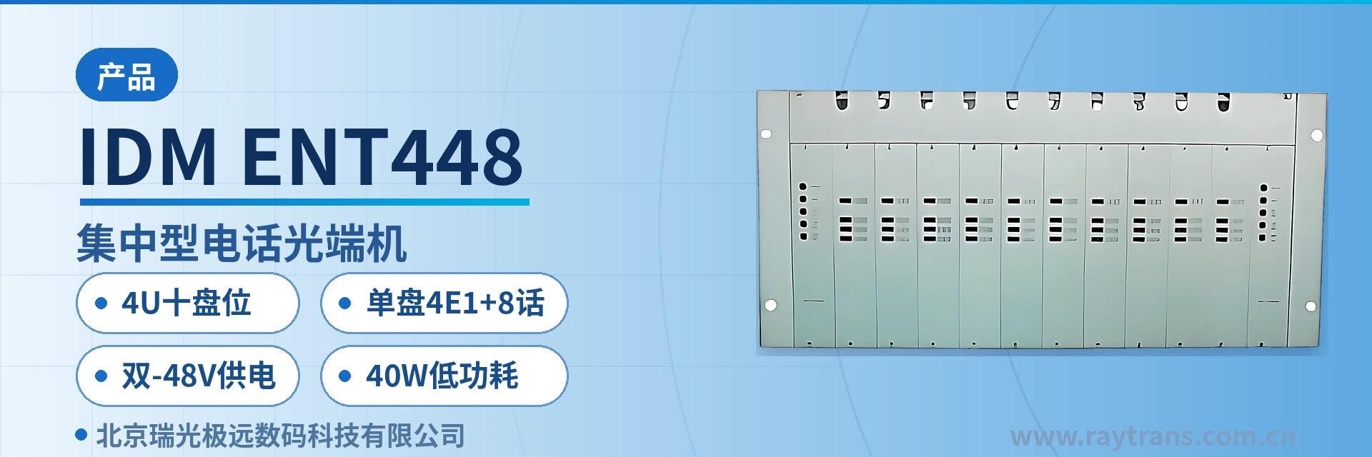
IDM-ENT448 Centralized Telephone Optical Multiplexer
4U ten-slot, 8 telephone ports and 4 E1 ports per card, 4 Ethernet ports, one chassis replaces three units
IDM-ENT448 centralized multi-service optical multiplexer, 19-inch 4U standard card-based chassis; IDM-ENT448 centralized multi-service optical multiplexer provides dual -48 V power supply; 10 service card slots; each service card provides 4 Ethernet service ports, 4 E1 service interfaces, and 8 telephone service interfaces;
IDM-ENT448 is a 4U ten-slot centralized telephone optical multiplexer developed by Beijing Ruiguang Jiyuan Digital Technology Co., Ltd. It is a multi-service optical multiplexer product for private network access scenarios, used to multiplex analog telephone, E1 trunk and Ethernet services onto a single 155Mbps optical transmission channel. As a centralized equipment of the optical multiplexer manufacturer Raytrans, this product is often presented in the product showcase together with government private network optical fiber communication solutions and military emergency communications vehicle solutions.
The equipment adopts a 19-inch 4U standard card-based chassis, providing 10 service card slots and dual -48V power supply. A single service card provides 8 telephone channels, 4 E1 and 4 Ethernet interfaces at the same time. As a centralized multi-service optical multiplexer, a single chassis can handle the voice, trunk and data access of one site, eliminating the rack space and optical fibers occupied by stacking multiple single-service devices; for government private network optical fiber communication solutions and military emergency communications vehicle solutions that require the deployment of telephone optical multiplexers and optical multiplexer equipment, this centralized multi-service optical multiplexer helps simplify the site equipment hierarchy.
Key specifications at a glance: 4U ten-slot · 4E1+8 voice channels per card · dual -48V power supply · 40W low power consumption · 4 Ethernet ports per card · 155Mbps optical port
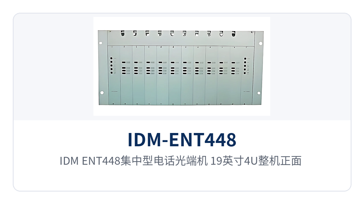
Figure 1: IDM-ENT448 centralized telephone optical multiplexer, 19-inch 4U unit front view, 10 service card slots and alarm indicator LEDs
What kind of equipment is the 4U ten-slot centralized telephone optical multiplexer
The 4U ten-slot centralized telephone optical multiplexer divides chassis capacity by service card slots: 10 slots carry voice channels, trunk and data services, and the number of interfaces grows with the number of inserted cards. It is one of the product showcase solutions that Raytrans offers for centralized sites. The IDM-ENT448 chassis measures 440×230×176mm, and the 19-inch 4U structure occupies 4U of installation space in a standard cabinet. The panel is provided with a function control switch and alarm indication.
When fully equipped with 10 service cards, a single chassis can provide 80 telephone channels, 40 E1 groups and 40 Ethernet interfaces, and the traffic and data counts of a medium-sized site can usually be fully provisioned in one chassis. There is no need to fully equip it at the initial stage of commissioning; insert cards according to the actual service list first, and then expand capacity by inserting additional cards later, while the chassis, backplane and power supply structure remain unchanged.
The capacity accounting of this card-based optical multiplexer is clear: card slots, number of telephone channels, number of E1 groups and number of Ethernet ports correspond one to one. As a 19-inch 4U optical multiplexer, the cabling area outside the chassis and adjacent rack space need to be reserved separately, and the equipment room space can be calculated as 4U plus the cabling area.
Key specifications: optical port, telephone, E1 and Ethernet interface specifications
The following table lists the capabilities of the IDM-ENT448 in two groups, functions and performance: the function table covers the chassis, card slots and service interfaces, and the performance table covers the optical port, telephone, E1, Ethernet, power supply and environmental conditions. When checking the configuration list and preparing bid responses, simply use the rows as needed; the parameter definitions and applicable conditions are listed together.
Function overview
| Function | Description |
|---|---|
| 4U ten-slot card-based chassis | 19-inch 4U standard card-based chassis, providing 10 service card slots; capacity expansion is done by inserting additional cards without replacing the complete unit |
| Multi-service access per card | A single service card provides 8 telephone channels, 4 E1 groups and 4 Ethernet interfaces, with all three service types accessed on the same card |
| Dual -48V power supply | The chassis is designed for dual -48V DC power supply and can connect to the DC power supply of a communications equipment room; AC 220V power supply is also optional |
| Function control and alarm indication | The panel provides a function control switch and alarm indication, so service and power supply status can be read directly on the front of the chassis |
| 155M optical transmission channel | Telephone, E1 and Ethernet services are multiplexed into a single 155Mbps optical channel, and a pair of optical fibers completes inter-site interconnection |
| Centralized networking | Services are extended using the optical fiber interfaces, digital trunk ports or analog subscriber interface resources of the central office switch, replacing remote small offices |
Interface and performance specifications
| Item | Parameter/Specification | Description/Applicable Conditions |
|---|---|---|
| Chassis structure | 19-inch 4U standard card-based chassis | Dimensions 440×230×176mm, for standard cabinet installation |
| Service card slots | 10 | Single card configuration: 8 telephone channels + 4 E1 groups + 4 Ethernet ports |
| Optical interface type | FC (SC and others can be customized) | Selected according to the on-site optical cable termination method |
| Fiber mode | Single-mode (multi-mode optional) | Selected according to link conditions; transmitter and receiver configured as a pair |
| Optical line rate | 155Mbps±50ppm | Telephone, E1 and Ethernet services share one optical channel |
| Wavelength | 1310nm | Configured as a pair with the peer device |
| Transmit optical power | -2 to -11dBm | Output optical power at the transmit side |
| Receiver sensitivity | Better than -36dBm | Lower limit of optical power for normal operation at the receive side |
| Telephone interface | Audio range 300Hz to 3400Hz, three-element complex impedance 200Ω+560Ω//0.1μF | ITU G.711 A-law companding, loop current 25mA per channel |
| E1 interface | Bit rate 2048Kbps, line code HDB3, supports ITU-T G.703, impedance 75Ω/120Ω | Frame structure PCM30/31, channel-associated signaling |
| Ethernet interface | RJ-45, 10/100Base-T, 10M/100M | Supports IEEE802.3, full/half duplex/adaptive |
| Power supply mode | DC-48V or AC 220V | Chassis configured with dual -48V power supply |
| Overall power consumption | 40W±10% | Overall chassis power consumption, including power used when service cards are operating |
| Operating temperature | 0℃ to 40℃ | Humidity ≤90% (non-condensing) |
How 4 Ethernet ports, 4 E1 and 8 telephone channels per card coexist in one chassis
Inside the equipment, voice is compressed into a 64Kbit/s stream according to ITU-T G.711 A-law, loaded into E1 time slots in a PCM30/31 frame structure, and then multiplexed together with Ethernet services into the 155Mbps optical channel. The E1 interface has a bit rate of 2048Kbps and HDB3 line code, complies with ITU-T G.703, offers selectable 75Ω or 120Ω impedance, and uses channel-associated signaling.
The three service types each use independent channels on the same service card, without rewriting each other or occupying each other's bandwidth. This is also why a single board can replace a small transmission device: after one optical fiber enters the site, voice channels, trunk and data are distributed to their respective interfaces within the same chassis.
- Telephone channel: analog voice channels are encoded with G.711 and then enter 64K time slots; a single card provides 8 lines, with a loop current of 25mA per channel, and can connect to telephones, fax machines and switching equipment.
- E1 channel: a single card provides 4 E1 groups, with a bit rate of 2048Kbps and HDB3 line code, PCM30/31 frame structure, used for trunk extension or connection to existing PCM and SDH equipment.
- Ethernet channel: a single card provides 4 RJ-45 electrical ports, 10/100Base-T adaptive, compliant with IEEE802.3, with selectable full/half duplex, carrying service data and surveillance backhaul.
All interfaces use industry-standard specifications, and the on-site value this brings is that the wiring method is consistent with existing systems. The exchange side accesses via E1 or analog subscriber interfaces, the user side assigns numbers by telephone, and the data side uplinks via RJ-45, so the engineering team does not need to add protocol conversion devices for any particular service type.
What kind of sites are suited to dual -48V power supply and 40W overall power consumption
The chassis is designed for dual -48V DC power supply and connects directly to the DC power distribution cabinet or battery bank of a communications equipment room, sharing one DC power supply system with transmission and switching equipment. For AC scenarios, AC 220V power supply is optional, so the unit can also be installed when only mains power is available at the site; the power supply format is determined according to site conditions at the time of ordering.
The overall power consumption of 40W±10% is calculated for the complete chassis, equivalent to the power consumption of one lighting lamp per site. Low power consumption means more margin in battery backup time, less heat inside the chassis and a lighter load on equipment room air conditioning, and unattended sites can cover the planned backup time with a conventional battery configuration.
- Check before power-on: confirm the DC voltage level and polarity, air switch capacity and grounding method; the two power feeds of the dual -48V supply should be taken from different air switches.
- Monitor during operation: check whether the chassis alarm indication and power status indication are normal, and observe whether the equipment runs stably during battery discharge tests.
- Recheck during capacity expansion: after inserting additional service cards, recheck the air switch and battery capacity against the full-load figures, and recalculate power consumption based on the incremental consumption per card.
How to install and commission
Installation and commissioning proceed in the following order: chassis positioning, optical path termination, card configuration and service verification are carried out in four stages. Record the correspondence between card slots and interfaces after each step; subsequent capacity expansion, fault location and O&M handover will all be based on this record.
- Chassis positioning: secure the 19-inch chassis in a standard cabinet according to the 4U space, and position the cabling area and cable trays according to the construction drawings.
- Optical path termination: the optical interface is FC (SC and others can be customized), single-mode fiber (multi-mode optional), and the 1310nm wavelength is configured as a pair with the peer end.
- Power connection: connect dual -48V DC or AC 220V according to site conditions; the two DC power feeds should be taken from different air switches and properly grounded.
- Card configuration: insert service cards according to the service list; a single card provides 8 telephone channels, 4 E1 groups and 4 Ethernet ports, and the card slot numbers correspond one to one with the service ledger.
- Interface matching: connect telephones or switching equipment to the telephone interfaces, use coaxial or balanced cables for E1 according to 75Ω/120Ω, and connect data devices to the Ethernet ports.
- Power-on verification: observe the panel alarm indication, spot-check voice channel call quality, E1 channel bit errors and Ethernet link status, and record the results for archiving.
Differentiated value
The three capabilities correspond respectively to rack space, power supply adaptability and private network interfacing cost. The following table maps each capability to its on-site value. When comparing selections and prices, extract the items you need row by row; the data comes from the product showcase materials and can be quoted directly in project responses. The capability descriptions in the table are consistent with the parameter table, so technical review and commercial price comparison can use the same set of facts.
| Differentiation Point | Specific Capability | Corresponding On-Site Value |
|---|---|---|
| 4U ten-slot high density | The 19-inch 4U chassis provides 10 service card slots, and a single card integrates 8 telephone channels, 4 E1 groups and 4 Ethernet ports | Voice, trunk and data of one site are consolidated in one chassis, reducing both cabinet space and the number of fiber cores |
| Dual -48V power supply and 40W power consumption | Dual -48V DC power supply, AC 220V optional, overall power consumption 40W±10% | Connects directly to the equipment room DC power supply and battery, with ample backup margin and a light heat dissipation burden at unattended sites |
| E1 dual impedance and channel-associated signaling | Supports ITU-T G.703, selectable 75Ω/120Ω impedance, PCM30/31 frame structure, channel-associated signaling | Connects directly to existing PCM, SDH and private network switching equipment without adding protocol conversion devices |
Typical application scenarios
The three types of private networks have different priorities for the IDM-ENT448 multi-service optical multiplexer: electric power and rail transit value the number of voice channels and interface compatibility, while military and armed police private networks place more emphasis on power supply continuity and equipment independence. The following describes the networking position and configuration points by industry, making it easy to determine the number of cards according to site scale.
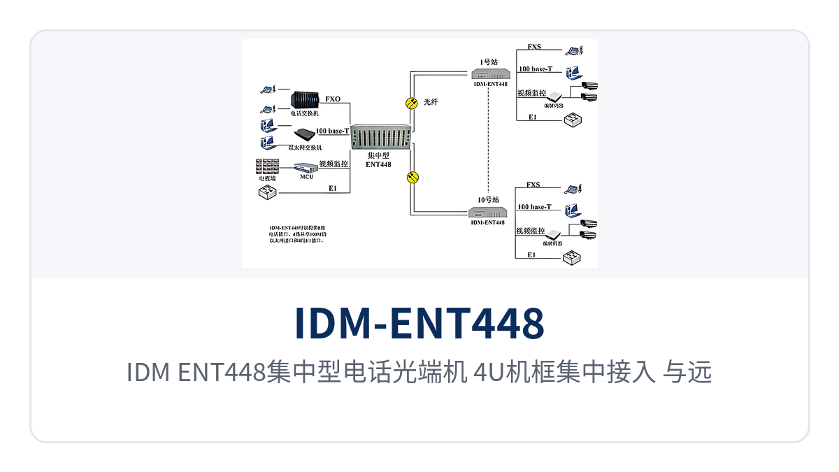
Figure 2: IDM-ENT448 centralized telephone optical multiplexer, 4U chassis centralized access, point-to-point networking topology with remote stations
Electric power private network: substation dispatch telephone and telecontrol data backhaul over the same fiber
Substations and power supply stations are distributed along the lines, and it is necessary both to ensure continuous availability of dispatch telephones and to backhaul telecontrol data and in-station surveillance to the dispatch center. The IDM-ENT448 performs centralized access on the substation side: dispatch and administrative telephones are assigned numbers via the telephone interfaces, the trunk to the dispatch center is extended via the E1 interfaces, and telecontrol data and surveillance backhaul go through the Ethernet interfaces. As an optical multiplexer for government private network optical fiber communication solutions and electric power private networks, this model completes the converged backhaul of voice, trunk and data services within the same chassis.
The number of voice channels is provisioned by inserting cards in tiers according to site traffic; small stations start with one or two service cards, while hub stations are planned for full configuration of 10 cards. The standard cabinet in the substation equipment room reserves 4U of rack space, and the card-based chassis is arranged adjacent to the cabling area, keeping the inspection and card replacement routes short.
Rail Transit: Centralized Voice Channel Access at Stations and Section Duty Points
Stations, depots and section duty points along a rail transit line are distributed along the route. The number of telephones varies considerably with station class, and E1 channels are also required between stations to carry dedicated communication services. The IDM-ENT448 is configured in a card-based manner according to site traffic. E1 interfaces are used for inter-station trunk extension, and Ethernet interfaces carry station service data and video backhaul.
The 19-inch 4U chassis facilitates unified installation in the communications equipment room. Sites along the line stock spare cards of the same model, reducing the variety of spare parts. Section duty points are mostly unattended, and dual -48V power supply and 40W-level power consumption place low demands on storage batteries and equipment room heat dissipation.
Military and Armed Police Private Networks: Independent Transmission of Duty Post Telephones and Private Network Data
Military and armed police private networks have clear requirements for call availability and link independence. Communications between duty posts, garrison points and command nodes are organized independently over the private network. In the military emergency communications vehicle solution, the IDM-ENT448 can likewise provide centralized access at the duty post side: the exchange side accesses via E1 or analog subscriber interfaces, the user side provisions subscriber lines to telephones at each job role, and private network data is uplinked through Ethernet interfaces. The three types of services share a single optical fiber.
The equipment is installed centrally in cabinets in the equipment room. Panel alarm indications and card slot numbers are the basis for on-site fault location. Replacing a service card stocked by number completes the replacement, and communications recovery at the site does not depend on manufacturer attendance on site. Duty posts usually do not have professional maintenance resources; panel alarms and card slot numbers are intuitive enough for duty personnel to report the fault location clearly over the telephone.
Conclusion
The 4U ten-slot centralized telephone optical multiplexer consolidates capacity, interfaces and power supply into a single chassis: the IDM-ENT448 uses 10 service card slots to provide 80 telephone channels, 40 E1 groups and 40 Ethernet channels, and a single card can carry all three types of services simultaneously. Dual -48V power supply and 40W±10% overall power consumption suit unattended sites. As a professional optical multiplexer manufacturer, Raytrans continues to provide practical product showcase and selection support for private network users in electric power, rail transit, and military and police sectors.
For electric power, rail transit, and military and police private networks, the value of this card-based optical multiplexer lies in capacity expansion by card and maintenance by card: capacity growth is met by adding cards, faulty cards are replaced while powered, and the chassis and wiring remain untouched. The specific card configuration and interface type are determined according to the site service list, and the parameters are subject to Raytrans' manufacturer's technical documentation and commercial confirmation.


