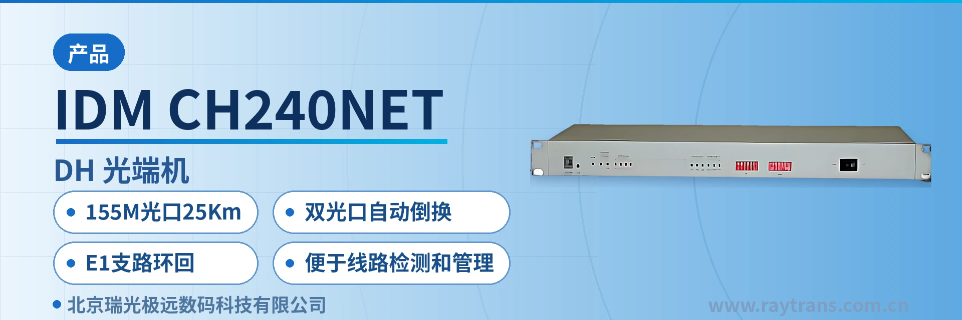
IDM-CH240NET PDH Optical Multiplexer
E1 and Ethernet mixed transmission over one fiber saves one optical multiplexer and media converter; E1 tributary loopback; dual
The 240NET series PDH optical multiplexer is an optical transmission device developed on the basis of large-scale integrated circuits. It implements mixed multiplexing and optical transmission of transparent E1 circuits and 100M line-rate Ethernet data channels; full-duplex/half-duplex adaptive
The 8-channel E1 plus Fast Ethernet PDH optical multiplexer is a type of access equipment that multiplexes multiple narrowband E1 circuits and Ethernet data onto the same optical fiber for transmission. Developed by Beijing Raytrans, it is used for E1 channel and IP data backhaul between private network sites. The equipment is deployed as a pair: one end connects the existing services at the site and converts them into optical signals, while the other end restores the corresponding E1 and RJ-45 interfaces. Only one optical fiber link is required between the two points. It is a typical PDH optical multiplexer for private network access scenarios in the product showcase.
The IDM-CH240NET PDH optical multiplexer provides 8 groups of transparent transmission E1 circuits and 2 groups of line-rate 100M Ethernet interfaces with VLAN partitioning in a single enclosure. The two types of services are sent out together through a 155Mbps optical port, with adaptive full-duplex and half-duplex operation. At the site side, there is no need to configure a separate E1 optical multiplexer and a separate media converter for E1 services and IP services, and the number of rack positions, power supply modules and cabling in the cabinet is reduced accordingly. As a multi-service optical multiplexer, it carries E1 and Ethernet services simultaneously on a pair of devices, which also reflects the integration approach of optical multiplexer manufacturers at the access layer. On this basis, Raytrans can provide compact optical multiplexer equipment required for government private network optical fiber communication solutions and military emergency communications vehicle solutions.
Key Specifications at a Glance: 155M optical port 25Km · 8 E1 + 2×100M · dual optical port automatic switchover · E1 tributary loopback · ITU-T G.703 (75 Ω/120 Ω) · overall power consumption ≤40W
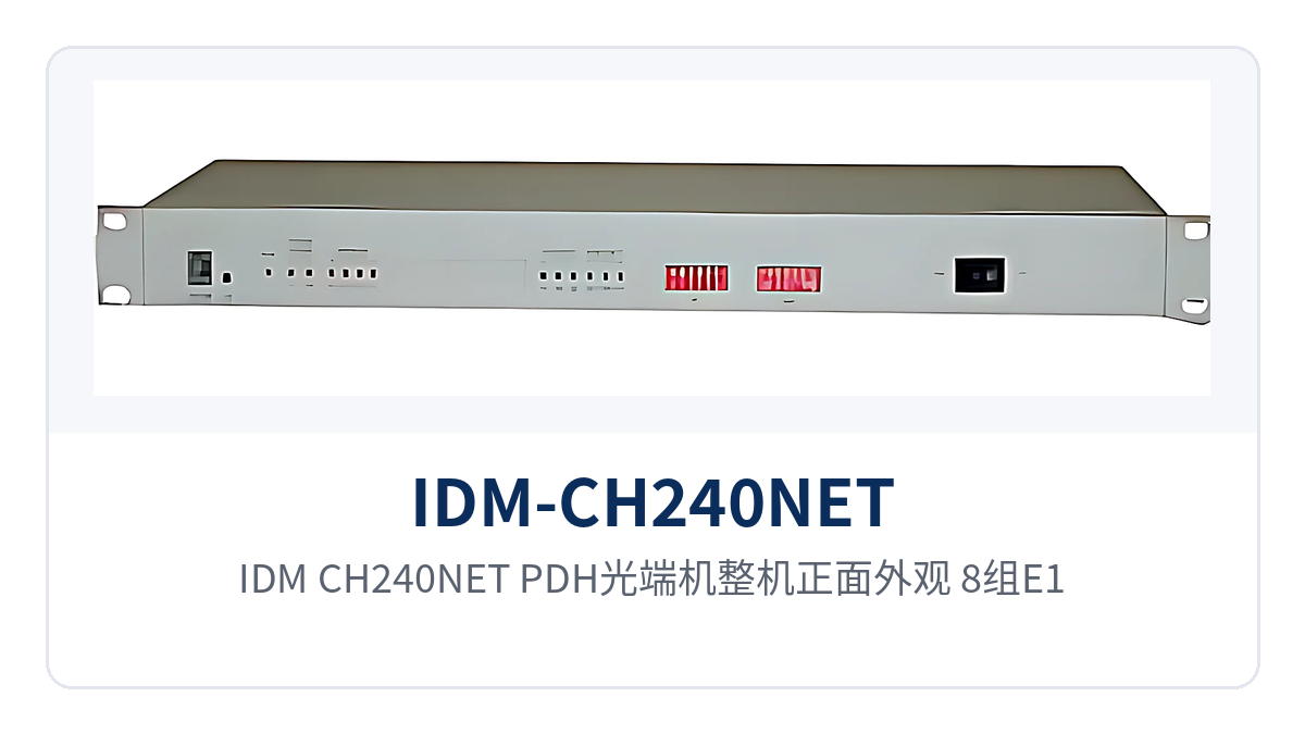
Figure 1: Front view of the IDM-CH240NET PDH optical multiplexer, showing 8 E1 and 2 Fast Ethernet interfaces and operation/alarm indicator LEDs
How the 8-Channel E1 Plus Fast Ethernet PDH Optical Multiplexer Transmits Two Types of Services over One Fiber
The capacity calculation for same-fiber multiplexing is straightforward: each group of E1 occupies 2.048Mbps, so 8 groups of E1 total about 16.4Mbps, and the 2 Ethernet groups share 100M line-rate bandwidth on the optical path. The two types of services together remain within the 155Mbps optical port capacity, so they can travel over the same optical path. Existing lines with limited fiber cores do not need capacity expansion for this purpose; the upgrade only involves the equipment at both ends. This is exactly the typical value of PDH optical multiplexers in existing network upgrades, and it is also a key scenario that many optical multiplexer manufacturers continue to optimize in their product showcase.
The E1 channels operate in transparent transmission mode in accordance with ITU-T G.703, without parsing or modifying the time slot content. Signaling is transmitted together with the services, so existing PCM multiplexers, digital trunks and dispatch devices can be connected without modification. The Ethernet channels transmit and receive in accordance with IEEE802.3, and the two groups of interfaces can be partitioned by VLAN to carry different service domains such as surveillance, office and production separately. For multi-service optical multiplexer applications that need to carry voice and data simultaneously, this design of mixed E1 and Ethernet transmission exactly matches the need in government private network optical fiber communication solutions for smooth migration of existing TDM services.
What Functions and Interfaces One Device Can Carry
The IDM-CH240NET covers four categories of functions—E1 access, optical transmission, Ethernet multiplexing and link protection—with eight capabilities in total. Their functions and applicable conditions are listed in the table below. During selection and acceptance, check row by row against the on-site service list to confirm whether the number of E1 channels, interface type and redundancy configuration match the requirements, so as to avoid discovering interface mismatches only after rack installation. In the product showcase of this series, Raytrans clearly lists the applicable boundaries of each function for engineering personnel to compare quickly.
| Function | Description |
|---|---|
| 8 groups of E1 transparent transmission | Provides 8 groups of transparent transmission E1 channels in accordance with ITU-T G.703, with a bit rate of 2048Kbps and HDB3 line code. The time slot content is passed through as-is and can interconnect with PCM multiplexing and dispatch equipment. |
| 155Mbps optical transmission | The optical port transmission rate is 155Mbps, with a standard single-mode transmission distance of 25Km. Long-distance optical modules can be installed to extend the link further. |
| 2 groups of line-rate 100M Ethernet | Provides 2 groups of RJ-45 interfaces, 10M/100M adaptive, compliant with IEEE802.3, sharing line-rate 100M bandwidth and allowing service domains to be partitioned by VLAN. |
| Optional dual optical port redundancy | Dual optical ports are optional, supporting forced switchover or automatic protection switching, so that services are transferred to the standby optical port when one fiber is interrupted. |
| E1 tributary loopback | Supports E1 tributary loopback, forming a test loop locally at the equipment side to determine whether the fault lies in the equipment, the optical path or the peer end. |
| Local/remote alarm monitoring | Provides comprehensive local and remote alarm indications. When the optical path or an E1 channel is abnormal, both ends give indications, and remote faults can be judged remotely. |
| Optional dual power supply | Dual power supply is optional. AC220V and DC-48V formats can be connected according to site conditions, preventing a single power feed from becoming a single point of failure. |
| Adaptive full/half duplex | The Ethernet ports support full-duplex, half-duplex and adaptive operating modes, automatically negotiating rate and duplex mode with the peer device. |
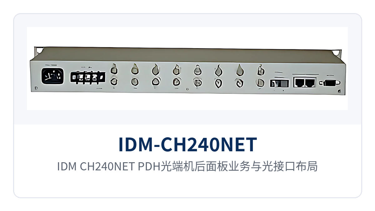
Figure 2: Rear panel service and optical interface layout of the IDM-CH240NET PDH optical multiplexer, showing 8 E1 interfaces, 2 Fast Ethernet ports, FC optical ports and power terminals
Key Specifications: Optical Interface, E1, Ethernet and Power Supply Environment
The specifications of the optical interface and service interfaces determine whether the link can be established: on the optical side, the link margin is calculated based on transmit optical power, receiver sensitivity and transmission distance; on the electrical side, compatibility with the peer device is checked based on impedance and frame structure. The parameters in the table below follow the product documentation. Where ordering configurations and on-site conditions differ, the manufacturer's technical documentation and commercial confirmation shall prevail.
Optical Interface and E1 Interface Parameters
| Item | Parameter/Specification | Description/Applicable Conditions |
|---|---|---|
| Optical interface type | FC (SC and others customizable) | Selected according to the peer optical fiber adapter and patch cord type |
| Fiber mode and wavelength | Single-mode (multi-mode optional), 1310nm/1550nm | Selected according to on-site optical cable conditions; used in pairs at both ends |
| Transmission rate | 155Mbps | A single optical path carries 8 groups of E1 and 2 Ethernet channels |
| Transmit optical power | -2~-11dBm | Factory specification, used for link attenuation calculation |
| Receiver sensitivity | Better than -36dBm | Bit errors are likely when received optical power is below this value |
| Transmission distance | 25Km | Standard optical module; long-distance optical modules can be installed for longer distances |
| Number of E1 channels | 8 groups | IDM-CH120NET has 4 groups; IDM-CH480NET has 16 groups |
| E1 bit rate and line code | 2048Kbps, HDB3 | Compliant with ITU-T G.703 |
| E1 impedance | 75 Ω/120 Ω | Select coaxial or balanced wiring according to the peer device |
| E1 frame structure and signaling | PCM30/31, channel-associated signaling | Interconnects with existing PCM networks using the same frame structure |
Ethernet, Power Supply and Environmental Parameters
| Item | Parameter/Specification | Description/Applicable Conditions |
|---|---|---|
| Ethernet interface | RJ-45, 10M/100M adaptive | 2 groups, compliant with IEEE802.3 |
| Ethernet operating mode | Full/half duplex/adaptive | Automatically negotiated with the peer device |
| VLAN partitioning | Supported | The two groups of interfaces are partitioned by service domain, sharing 100M line rate on the optical path side |
| Power supply mode | AC220V/DC-48V | Dual power supply optional; connected to on-site AC mains power or DC communications power supply |
| Overall power consumption | ≤40W | Calculated according to site power supply capacity and cabinet heat dissipation conditions |
| Operating temperature | 0℃~50℃ | Equipment room and equipment cabinet environment |
| Relative humidity | 0~95% (non-condensing) | Normal operation under non-condensing conditions |
| Enclosure dimensions | 440×230×45mm | Height 45mm, occupying little space in the cabinet |
How Dual Optical Port Redundancy and E1 Tributary Loopback Enable Self-Healing and Fault Diagnosis
Dual optical port redundancy addresses the problem of service stoppage after a fiber interruption: with two optical ports configured, the equipment supports both forced switchover and automatic protection switching. Forced switchover is used during planned maintenance to route services to a specified optical port, while automatic protection switching transfers services to the standby optical port when a fiber is unexpectedly interrupted. The dual optical port automatic switchover function is particularly important for military emergency communications vehicle solutions—on-vehicle optical cable routing conditions are complex, and whether the link can recover automatically upon interruption directly affects the continuity of emergency services. The switchover mode and switching time are subject to the manufacturer's technical documentation and commercial confirmation. A switchover drill is recommended before formal commissioning.
E1 tributary loopback addresses the problem of determining where a fault lies: by forming a test loop on the local equipment and combining it with local/remote alarm indications, the problem can be narrowed down to the equipment, the optical cable or the peer device, without first traveling to the remote site. For unattended sites distributed along the line, this capability directly determines whether troubleshooting is completed the same day or the next day. In the product showcase of this PDH optical multiplexer, Raytrans also lists E1 tributary loopback as one of the core means of O&M fault diagnosis.
On-site troubleshooting proceeds in three steps—alarms, loopback and optical power—which are progressive: the observation result of the previous step determines how to proceed with the next, so O&M personnel do not need to rely on guesswork, and conclusions can be readily shared with remote duty personnel, shortening the time spent on repeated confirmation between the two ends.
- First check the alarm indications of the optical ports and E1 tributaries at both ends to confirm whether the abnormality is on the optical path side or the E1 interface side;
- Perform E1 tributary loopback at the local end. If the local loopback is normal but the peer end is unreachable, the problem is most likely in the optical path or the peer device;
- Check whether the optical module transmit optical power (-2~-11dBm) and the received optical power meet the sensitivity requirement of better than -36dBm;
- Use the peer alarm records to narrow the fault down to a single station or a single segment, and then decide whether to dispatch personnel to the site.
Typical Application Scenarios
The IDM-CH240NET PDH optical multiplexer is mainly deployed in point-to-point mode: one unit at the service site and one unit at the central equipment room or centralized control station, with the two ends directly connected by optical fiber. After E1 and Ethernet are restored at the other end, they are connected back to the existing transmission and switching equipment. Site expansion only requires adjusting interface cards and cabling, without laying new optical cables. The following describes deployment positions and service allocation according to the actual networking approaches of three industries.
Electric Power Private Network: Telecontrol Channels and In-Station Data Between Substations and Dispatch Centers
Telecontrol data, protection signals and in-station IP services between substations, switching stations and dispatch centers usually belong to different channels. The IDM-CH240NET connects 8 groups of E1 services and 2 groups of Ethernet services separately within the station and sends them to the centralized control station over one optical fiber. E1 retains its original 2.048Mbps interface format, so existing PCM and telecontrol equipment in the station do not need to be replaced. As a mature multi-service optical multiplexer, this model plays a connecting role in the electric power private network and also provides a reusable deployment approach for site access in government private network optical fiber communication solutions.
Electric power sites are mostly unattended. Power is supplied at DC-48V according to the in-station communications power supply, and the optional dual power supply keeps services online when one power feed is abnormal. When optical cables are damaged by road construction or severe weather, the optional dual optical port redundancy provides a standby optical path, and the alarm indications at both ends help quickly locate the damaged section.
Rail Transit Communication: Channel Extension for Stations Along the Line, Section Equipment Rooms and Depots
Sites along a rail transit line are distributed and far apart. Dedicated telephone, PA and monitoring data need to be transmitted between stations and section equipment rooms, where only limited fiber cores and rack positions are often available. The IDM-CH240NET has enclosure dimensions of 440×230×45mm and can be installed in standard cabinets along the line. Its 8 groups of E1 and 2 Ethernet channels are transmitted over the same fiber, so the space and number of cables occupied at the site side are relatively small.
Power supply formats at sites along the line are not uniform. AC and DC power supply modes can be configured station by station, reducing the variety of spare parts. The operating temperature range of 0℃~50℃ makes it suitable for communications equipment rooms and equipment cabinets with ventilation, and convenient for installation in the same cabinet as other transmission devices.
Military and Government Private Networks: Service Access for Remote Sites and Temporary Command Posts
Sites on military and government private networks are often located in remote areas with limited duty conditions, placing concentrated demands on service continuity and on-site maintainability. IDM-CH240NET performs fault diagnosis locally through E1 tributary loopback and local/remote end alarm indication, reducing the number of site visits and making it suitable for equipment rooms at the remote end and field stations with limited manpower. In military emergency communications vehicle solutions, the device enables rapid service commissioning once deployed in a paired configuration, and it is also a typical product form from optical multiplexer manufacturer Raytrans for private network access scenarios.
Temporary command posts or mobile sites usually require rapid commissioning. Once the devices are deployed in a paired configuration and connected to optical fibers, the E1 and Ethernet interfaces are restored without changing the configuration of the opposite-end equipment. The point-to-point channel structure makes link relationships clear and facilitates temporary adjustment of node locations according to mission requirements.
Selection and Deployment
Start selection by counting channels: the number of E1 service channels determines which model to choose, while Ethernet service volume and segmentation requirements determine whether ports should be planned by VLAN. The three models share the same Ethernet configuration, all providing 2 groups of 100M interfaces; they differ in the number of E1 channels and the corresponding site service scale. Simply configure one tier above the confirmed number of channels; there is no need to estimate by peak values and leave excessive margin.
| Model | E1 Channels | Ethernet Interfaces | Applicable Sites |
|---|---|---|---|
| IDM-CH120NET | 4 groups | 2 groups of 100M | End stations with smaller service volume and small equipment rooms |
| IDM-CH240NET | 8 groups | 2 groups of 100M | Medium-scale sites and section communication nodes |
| IDM-CH480NET | 16 groups | 2 groups of 100M | Aggregation stations with more E1 channels and service-concentrated sites |
IDM-CH240NET corresponds to the 8-group E1 and 2-group 100M configuration in this series and is the standard model of the 8-channel E1 optical multiplexer. Deployment proceeds in five steps, from optical path calculation and interface setup to power supply access, redundancy configuration, and service commissioning. Each step has verifiable checkpoints; complete them on site in sequence before proceeding to the next:
- Verify the optical path: use standard optical modules for single-mode distances within 25Km, select long-distance optical modules for greater distances, and calculate the link margin based on a transmit optical power of -2 to -11dBm and a receiver sensitivity better than -36dBm.
- Set the interfaces: select 75 Ω coaxial or 120 Ω balanced wiring for E1 according to the opposite-end equipment; the Ethernet ports are adaptive 10M/100M, and VLANs are divided by service domain.
- Connect the power supply: connect AC220V or DC-48V according to site conditions; when dual power supplies are configured, the two feeds should come from mutually independent power sources.
- Configure redundancy: when dual optical ports are required, set forced switchover or automatic protection switching, and perform a switchover drill to confirm normal service.
- Commission services: verify channels one by one using E1 tributary loopback, check the local/remote end alarm indications, and then put the system into formal operation.
Conclusion
As an 8-channel E1 Fast Ethernet PDH optical multiplexer, IDM-CH240NET carries 8 groups of transparent E1 and 2 channels of wire-speed 100M Ethernet over a single 155Mbps optical fiber, with a standard transmission distance of 25Km. Optional dual optical port redundancy supports forced switchover and automatic protection switching, while E1 tributary loopback together with local/remote end alarm indication enables fault diagnosis at the remote end to be performed locally.
The IDM-CH240NET PDH optical multiplexer is suitable for site access on electric power private networks, rail transit communication, and military and government private networks. The two power supply formats, AC220V and DC-48V, can be configured per site. The CH120NET and CH480NET in the same series extend by E1 channel count, with 4-group and 16-group configurations respectively. The interfaces and power supply configurations listed in the product showcase can all be selected according to actual site requirements, and optical multiplexer manufacturer Raytrans can provide technical documentation and commercial support for the corresponding models.