
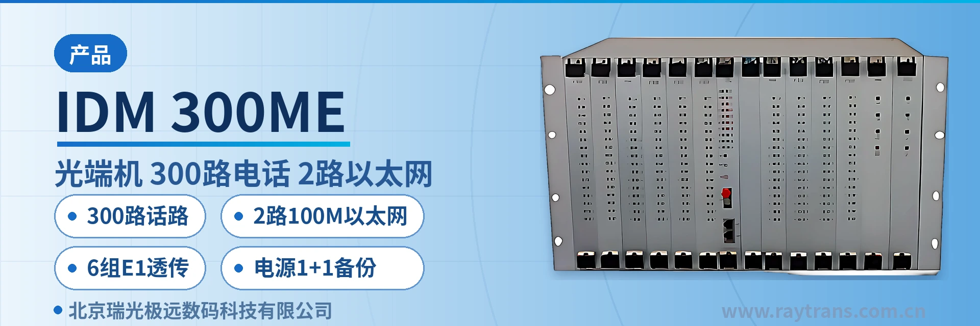
IDM-300ME Telephone Optical Multiplexer
A pair of optical fibers supports 300 voice channels in full configuration, replacing 600 meters of 64-core cable, 13 slots fully populated
The IDM-300ME multi-service optical multiplexer provides 2 shared line-rate 100M Ethernet interfaces and 6 E1 transparent transmission interfaces. It also provides FXO and FXS interfaces with caller ID (CID) and supports up to 300 user voice channels in full configuration.
The 13-slot card-based telephone optical multiplexer is a telephone access and optical fiber transmission device with a centralized card-based chassis structure. Its voice channel capacity is expanded by inserting additional service cards, and the card slot layout and expansion method are visible in the product showcase. The IDM-300ME telephone optical multiplexer is developed by Beijing Ruiguang Jiyuan Digital Technology Co., Ltd. It multiplexes 300 voice channels, 6 E1 transparent transmission interfaces, and 2 line-rate 100M Ethernet channels onto a single 155Mbps optical transmission channel.
A single pair of optical fibers carries 300 voice channels in full configuration and can directly replace 600 meters of 64-core cable. After the telephone optical multiplexer replaces the cable, cable investment and duct occupation decrease accordingly. The 300 voice channels are configured in service cards of 30 channels each, and E1 and Ethernet services are multiplexed over the same fiber. A single chassis handles all narrowband access at one site. As a multi-service optical multiplexer, this 300-channel telephone optical multiplexer can simultaneously carry voice, E1, and Ethernet services on one optical multiplexer platform.
Key Specifications at a Glance: 300 voice channels · 2 line-rate 100M Ethernet channels · 6 E1 transparent transmission groups · 1+1 mutual backup power supply · 13 card slots, all hot-swappable · 155Mbps optical line rate · 19-inch 6U centralized chassis
What is the 13-slot card-based telephone optical multiplexer
The 13-slot card-based telephone optical multiplexer divides chassis functions by card slot: 10 service card slots carry telephone services, 1 main control card slot manages the chassis, and 2 power card slots provide 1+1 mutual backup power supply. When the IDM-300ME telephone optical multiplexer is fully populated with 10 service cards, it reaches the full configuration of 300 user voice channels. Each service card provides access to 30 channels of 64K telephone audio service, and the number of card slots corresponds one-to-one with the voice channel capacity. As a 300-channel telephone optical multiplexer designed for private network scenarios, its card-slot product showcase intuitively presents the capacity expansion logic.
Narrowband voice and broadband Ethernet services are multiplexed within the chassis into the 155Mbps optical transmission channel. A single optical path carries both types of services simultaneously, simplifying the transmission line between sites. The division into service card slots, main control card slot, and power card slots allows both configuration and card insertion to be located by card.
The unit adopts a 19-inch 6U centralized chassis with product dimensions of 482×266×270mm, complies with telecom and carrier standards, and occupies 6U of installation space in a standard cabinet. All card slots support hot-swappable operation. During commissioning, cards are inserted one by one according to the service list; during O&M, faulty card slots are located by alarm and replaced online without powering down the entire unit. The card-based structure enables installation actions to be located by card and capacity expansion actions to be performed by inserting cards, making the equipment simple to install and easy to maintain.
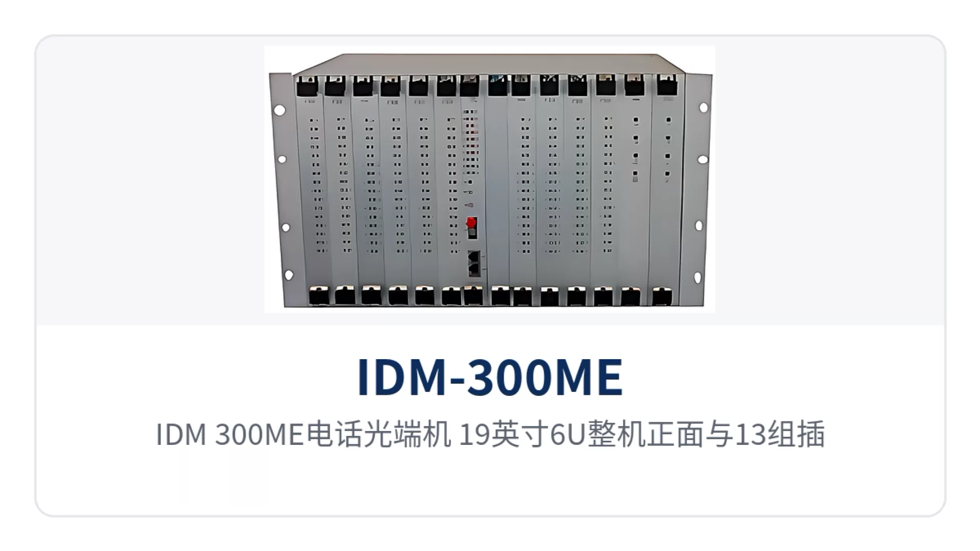
Figure 1: IDM-300ME telephone optical multiplexer 19-inch 6U front view and 13-slot card-based structure
How 300 voice channels replace 600 meters of 64-core cable with a pair of optical fibers
Using a pair of optical fibers to carry 300 voice channels in full configuration and replace 600 meters of 64-core cable is the direct engineering cost value of the IDM-300ME telephone optical multiplexer. According to the product documentation, the price of one pair of 300-channel telephone optical multiplexers is equivalent to the price of 600 meters of 64-core cable, and the voice channel capacity is provisioned at one time on the equipment side. The cost of a copper cable solution grows with distance, pair count, and construction workload, and duct and cable tray occupation increases accordingly, while the fiber side occupies only one pair of cores. This is the typical cost comparison for telephone optical multiplexers replacing cables in private network construction.
The internal path of voice channels within the equipment is as follows: the exchange side is connected through FXO interfaces, the user side is provisioned through FXS interfaces, voice is compressed into a 64Kbit/s stream using ITU G.711 A-law, organized into time slots in a PCM30/31 frame structure, and then multiplexed into the 155Mbps channel.
The peer device restores the signal to analog voice using the same format, with an audio range of 300Hz to 3400Hz and a loop current of 25mA per channel. Both FXO and FXS interfaces support caller ID and can directly connect to ordinary analog telephones, fax machines, and switching equipment.
The cost comparison for telephone optical multiplexers replacing cables can be calculated by link scale. The differences between the copper cable solution and the optical fiber solution are concentrated in three areas, and engineering teams compare investment and subsequent workload accordingly. When calculating, list cable, duct, termination, and construction as separate items, then compare them with the equipment-side investment, so the conclusion is easier to pass in project review.
- Medium occupation: Copper cables occupy ducts and cable trays by pair count, and the cable cross-section for 300 channels is far larger than that of a pair of optical fibers.
- Capacity expansion approach: Copper cable capacity expansion requires additional cables and terminations, while the fiber side only needs additional service cards in steps of 30 channels.
- Construction and maintenance: Copper cable laying, termination, and line tracing involve heavy workloads, while optical fiber termination is completed once, and maintenance is performed by card slot and alarm.
Functions and performance specifications
The functions of the IDM-300ME telephone optical multiplexer are divided by chassis structure, voice channel capacity, and service interfaces. The following table lists each function item and its corresponding capability description. Function items correspond one-to-one with card slots and interfaces, so on-site configuration verification can be done row by row.
| Function | Description |
|---|---|
| 13-slot card-based structure | The chassis provides 13 card slots, including 10 service card slots, 1 main control card slot, and 2 power card slots; voice channel capacity is expanded by inserting additional cards |
| 30-channel telephone access per card | Each service card provides access to 30 channels of 64K telephone audio service; 10 service cards in full configuration provide 300 user voice channels |
| 1+1 power supply backup | 2 power cards back up each other; if one power card fails, the other continues to supply power to the chassis |
| All card slots hot-swappable | All card slots support hot-swappable operation; faulty card slots can be replaced while the equipment is powered on, and services on other card slots continue running |
| Shared line-rate 100M Ethernet | 2 line-rate 100M Ethernet interfaces, RJ-45, 10/100M adaptive, supporting VLAN partitioning, capable of carrying service data and surveillance backhaul |
| 6 E1 transparent transmission groups | 6 E1 transparent transmission interfaces: 4 groups at 75Ω unbalanced and 2 groups at 120Ω balanced, selected according to the peer interface type |
| 155M optical transmission channel | Optical line rate of 155Mbps; narrowband voice and broadband Ethernet services are multiplexed into the same optical transmission channel |
| Caller ID voice channels | FXO and FXS interfaces support caller ID and can connect to analog telephones, fax machines, and switching equipment |
| Centralized 6U chassis | Centralized chassis design, standard 6U enclosure, compliant with telecom and carrier standards, with installation and maintenance located by card |
The parameters are subject to the product documentation. The following table covers optical interfaces, Ethernet, E1, FXO/FXS interfaces, power supply, and environmental conditions for networking design and selection verification. Parameter definitions and applicable conditions are listed together, and the configuration list and tender response can directly reference them.
| Item | Parameter/Specification | Description/Applicable Conditions |
|---|---|---|
| Chassis structure | Centralized chassis, standard 6U enclosure | 19-inch rack installation, dimensions 482×266×270mm |
| Number of card slots | 13 | 10 service card slots + 1 main control card slot + 2 power card slots |
| Main control card | 1 set of CMU central control and management card | Handles access and management of service cards within the chassis |
| Capacity per card | 30 channels of 64K telephone audio service | Each service card provides access to 30 channels |
| User interface capacity | 300 user voice channels in full configuration | Composed of 10 service cards × 30 channels |
| Optical line rate | 155Mbps | Multiplexed transmission of narrowband and broadband services |
| Optical interface type | FC (SC and others can be customized) | Selected according to the on-site optical cable termination method |
| Fiber mode | Single-mode (multi-mode optional) | Selected according to link conditions |
| Wavelength | 850nm/1310nm/1550nm | Transmit and receive configured as a pair |
| Transmit optical power | -2 to -11dBm | Output optical power at the transmit side |
| Receiver sensitivity | Better than -36dBm | Lower limit of normal operating optical power at the receive side |
| Ethernet interface | RJ-45, 100M line rate (100Mbit/s) | 10/100M adaptive, compliant with IEEE-802.3u, supporting VLAN partitioning |
| E1 interface | 2048Kbps, HDB3 line coding | Supports ITU-T G.703, impedance 75Ω/120Ω, PCM30/31 frame structure, transparent transmission mode |
| E1 interface configuration | 6 E1 transparent transmission groups | 4 groups at 75Ω unbalanced + 2 groups at 120Ω balanced |
| FXO/FXS interface | Audio range 300Hz to 3400Hz | Three-element complex impedance 200Ω+560Ω//0.1μF, compression ITU G.711 A-law, loop current 25mA per channel |
| Power supply mode | DC-48V/AC220V (external) | 2 power cards configured in 1+1 mutual backup |
| Overall power consumption | ≤400W | In full configuration |
| Operating temperature | 0℃ to +40℃ | Humidity ≤90% (at 35℃), non-condensing |
At the private network networking level, this type of optical multiplexer can carry integrated voice and data access in government private network optical fiber communication solutions, and is also suitable for the rapid commissioning requirements for narrowband voice channels and Ethernet services in military emergency communications vehicle solutions. As an optical multiplexer manufacturer, Raytrans provides selection support from card slot configuration to optical path termination around its multi-service optical multiplexer product line, making it easy for projects to verify item by item according to voice channel scale and interface type.
How 13 card slots are configured for 300 voice channels in full configuration
Card slot configuration is based on the number of voice channels and service lines actually commissioned at the site. Service cards are inserted in steps of 30 channels, and full configuration is not necessary initially. When all 10 service card slots are populated, the full configuration of 300 user voice channels is reached. One main control card slot holds the CMU central control and management card, and 2 power card slots are configured in 1+1 backup, so the configuration accounting for the 13 card slots is closed. This card slot accounting corresponds exactly to the full configuration of the 300-channel telephone optical multiplexer and is the most intuitive capacity description in the product showcase.
Project implementation proceeds in the following order. Installation, cabling, and service card insertion are carried out separately, and on-site commissioning only requires item-by-item verification against the list. After each step, record the correspondence between card slots and interfaces; subsequent capacity expansion and fault handling will be based on this record.
- Position the chassis: Secure the chassis in the cabinet according to the 19-inch 6U space, and position the backplane and cabling area according to the construction drawings.
- Terminate the optical cable: The optical interface is FC (SC and others can be customized), single-mode fiber (multi-mode optional), and wavelengths 850nm/1310nm/1550nm are configured as a pair with the peer end.
- Insert the main control and power cards: Insert 1 CMU central control and management card and 2 power cards. Select DC-48V or AC220V (external) power supply according to on-site conditions.
- Insert service cards according to the voice channel list: Each service card inserted adds 30 voice channels; populating all 10 cards provides the full 300 channels.
- Match interfaces: Connect FXO to the exchange side and FXS to user telephones; select 75Ω unbalanced or 120Ω balanced for the 6 E1 transparent transmission groups; connect the 2 Ethernet channels to data devices.
- Power-on verification: Observe the card slot alarm indications, verify the number of voice channels activated on each card and the interface correspondence, and record and file the results.
After voice channel growth, capacity expansion still means inserting cards: the chassis with vacant service card slots continues to be used, cards are added in steps of 30 channels, and the configuration of the chassis, backplane, main control card, and power cards remains unchanged. Capacity planning is calculated based on the upper limit of 300 channels per chassis; beyond this scale, the number of chassis and site distribution must be planned separately.
How 1+1 mutual backup power supply and all-slot hot-swapping limit the impact to a single card
The IDM-300ME telephone optical multiplexer controls the scope of service interruption from two aspects: power supply and replacement. The 2 power cards operate in 1+1 backup; if one power card fails, the other continues to supply power to the chassis, and the unit does not stop working due to power loss of a single card. All card slots support hot-swappable operation; faulty cards can be removed and replaced while the equipment is powered on, and services carried by other card slots continue running.
The scope of fault impact is determined by the correspondence between card slots and services: a single service card corresponds to 30 channels of telephone audio service, so a single card failure affects the 30 voice channels on that card, while voice, the 6 E1 channels, and the 2 Ethernet services on other service cards are unaffected. On-duty personnel locate the specific card slot by alarm indication, and services recover after card replacement, without powering down the entire unit or stopping all services.
Sites in electric power, rail transit, and government private networks are mostly unattended, and a fault often means sending personnel on site. The centralized 6U chassis achieves maintenance without service interruption through spare card replacement and mutual power backup. Maintenance actions are simplified to card-by-card replacement, power supply risks are limited to a single card, and private network services can continue running during card-level faults.
How 2 line-rate 100M Ethernet channels and 6 E1 transparent transmission groups share one optical path with voice channels
Two 100M Ethernet channels, six groups of E1 transparent transmission and 300 voice channels share the same 155Mbps optical transmission channel. The three service types each occupy an independent channel within the chassis and do not overwrite each other. The Ethernet interface is RJ-45, with a transmission rate of 100M wire-speed (100Mbit/s), compliant with the IEEE-802.3u standard, 10/100M adaptive, supporting VLAN partitioning, and capable of carrying dispatch information systems, service data and surveillance backhaul.
There are six groups of E1 interfaces in total, of which four groups are 75 Ω unbalanced and two groups are 120 Ω balanced, selected according to the interface type of the opposite-end device. The E1 bit rate is 2048Kbps, the line coding is HDB3, and the frame structure is PCM30/31. It supports the ITU-T G.703 standard and operates in transparent transmission mode, so the original frame structure and service content remain unchanged during transmission, and it can interconnect with existing PCM and SDH equipment.
The engineering value of carrying three service types over one optical path lies in the simultaneous aggregation of equipment and links: telephone exchange-side access, user-side subscriber line provisioning, E1 trunk extension and data network interconnection are all planned on the same IDM-300ME telephone optical multiplexer. The site side no longer needs separate transmission devices for each service type, saving cabinet space and fiber cores accordingly, and both commissioning and capacity expansion are counted by card slot and interface. This form of multi-service multiplexing over the same fiber is exactly the typical value of a multi-service optical multiplexer in private network access scenarios.
Differentiation Point
The three capabilities correspond respectively to cable investment, service coverage and O&M reliability. The table below maps each capability to its on-site value item by item. When comparing prices and selecting models, extract the items you need by row, without cross-checking parameters across multiple pages. The data in the table comes from the product documentation, and the items can be quoted directly in responses.
| Differentiation Point | Specific Capability | Corresponding On-Site Value |
|---|---|---|
| 300 voice channels over a single pair of optical fibers | 300 voice channels at full configuration are transmitted over a pair of optical fibers; per the product documentation, the price of one pair of 300-channel telephone optical multiplexers is equivalent to that of 600 meters of 64-core cable | Directly replaces 600 meters of 64-core cable, saving investment in cable, conduit and termination construction |
| 2-channel 100M Ethernet + 6 groups of E1 transparent transmission | 2-channel 100M Ethernet (RJ-45, 10/100M adaptive, supporting VLAN partitioning) and 6 groups of E1 transparent transmission (4 groups at 75 Ω + 2 groups at 120 Ω) share the 155Mbps channel with voice channels | Narrowband voice and broadband data are multiplexed over one fiber; the site side no longer needs separate transmission devices, saving transmission lines |
| 13 card slots, full hot-swappable + 1+1 power supply redundancy | All 13 card slots (10 service cards, 1 main control card, 2 power cards) support hot-swappable operation; the power supplies provide 1+1 mutual backup in a centralized 6U chassis | Maintenance without downtime; a single board failure affects only the 30 voice channels on that board; unattended sites require fewer attendance trips |
Typical Application Scenarios
Electric Power Private Network: Dispatch Telephone and Telecontrol Data Backhaul over the Same Fiber
Electric power private networks deploy sites along the line. A substation must ensure continuous availability of dispatch telephones and also backhaul telecontrol data and in-station surveillance to the dispatch center. The IDM-300ME telephone optical multiplexer provides aggregate access at the substation side: dispatch and administrative telephones are provisioned through FXS interfaces, the E1 trunk to the dispatch center is extended through six groups of E1 transparent transmission interfaces, and telecontrol data and surveillance backhaul run over the two 100M Ethernet interfaces.
The number of voice channels is configured by provisioning service cards according to the site's traffic. A small station is equipped with a few service cards first, while a hub station is planned for 300 channels, with card slots reserved for future growth. The standard cabinet in a substation equipment room usually reserves rack positions for 6U; the card-based chassis is arranged adjacent to the wiring area, keeping inspection and card replacement routes short.
Rail Transit: Telephone and Section Service Channel Extension at Stations along the Line
Stations, depots and section duty posts of rail transit are distributed along the line. The number of telephones varies greatly with station class, and inter-station E1 channels are also needed to carry dedicated communication services. The IDM-300ME telephone optical multiplexer provisions service cards in a card-based manner according to station traffic. The six groups of E1 transparent transmission interfaces are used for inter-station trunk extension, and the two 100M Ethernet interfaces carry station service data and video backhaul.
The 19-inch 6U chassis facilitates unified installation in the communications equipment room. Spare card replacement at stations along the line does not require taking the whole unit out of service, and maintenance is performed by card slot. Section duty posts are usually unattended, and redundant card slot and power supply configurations reduce attendance trips caused by single board failures.
Military and Government Private Networks: Independent Networking of Site Telephones and Private Network Data
Military and government private networks have clear requirements for call availability and link independence, and communications among sites, duty posts and command nodes are organized independently over the private network. The IDM-300ME telephone optical multiplexer provides aggregate access at the site side in the private network: the central office connects to switching equipment through FXO interfaces, the user side completes subscriber line provisioning through FXS interfaces, and voice is encoded with G.711 and transmitted over the 155Mbps channel, sharing a pair of optical fibers with E1 trunk and data network services.
1+1 power supply redundancy and full-slot hot-swappable operation confine power supply and card slot failures to a single board, and on-duty personnel replace cards online according to alarms. The alarm indications and card slot numbers on the chassis front panel are the basis for on-site location; once a spare card is prepared according to the number, replacement can be completed without waiting for the manufacturer to attend on site.
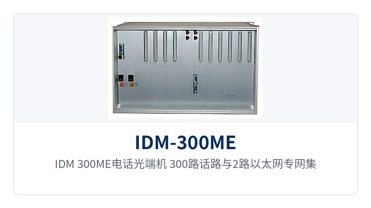
Figure 2: Overall schematic of the IDM-300ME telephone optical multiplexer for 300 voice channels and 2-channel Ethernet private network aggregate access
Conclusion
The 13-slot card-based telephone optical multiplexer carries private network telephone access in a card-based chassis: the 10 service cards of the IDM-300ME telephone optical multiplexer deliver 300 voice channels at full configuration at 30 channels per card, a single pair of optical fibers replaces 600 meters of 64-core cable, and the two 100M Ethernet channels and six groups of E1 transparent transmission share the 155Mbps optical channel with the voice channels. As a multi-service optical multiplexer, it handles voice, data and E1 services on the same platform, and the card slot configuration in the product showcase is clear at a glance.
1+1 power supply redundancy and full hot-swappable operation across 13 card slots confine the impact of failures to a single board, and the centralized 6U chassis enables maintenance without downtime. As an optical multiplexer manufacturer, Raytrans can determine card slot configurations and interface types according to site traffic for electric power private network, rail transit and government private network optical fiber communication solutions and military emergency communications vehicle solutions. Specific parameters are subject to the manufacturer's technical documentation and commercial confirmation.


