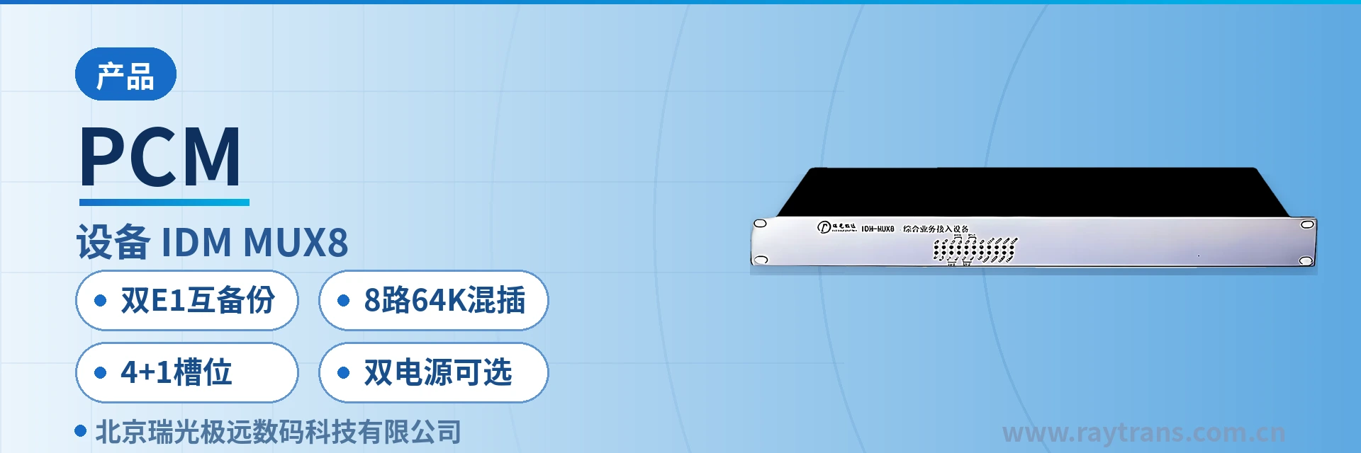
PCM Multiplexer IDM MUX8
Dual E1 mutual backup, 4+1 slots mixed insertion, one 1U unit replaces multiple single-service converters
The IDM MUX8 integrated service multiplexer provides dual E1 interfaces, adopts a 19-inch 1U standard chassis with 4 slot groups + 1 expansion slot group, and optional dual power supply of 220 V/-48 V. It supports services such as FXS/FXO, magneto, EM 2/4-wire, and RS232/RS422/RS485. The two E1 interfaces can be configured for mutual backup or time slot extraction mode.
The IDM MUX8 dual-E1 mutual backup PCM multiplexer is an integrated service access device developed by Beijing Ruiguang Jiyuan Digital Technology Co., Ltd. (Raytrans). It consists of a 19-inch 1U standard chassis, two E1 line interfaces, and 4 slot groups plus 1 expansion slot group, and is used to multiplex 64K services such as telephone, magneto, EM audio, and serial port data onto E1 channels for transmission, completing product showcase and centralized access for multiple services.
The device targets private network sites that reserve only one or two E1 lines on the line side while carrying a mix of service types on site, and can be deployed on the site side of government private network optical fiber communication solutions, smart mining communication solutions, and military emergency communications vehicle solutions. The two E1 lines can be configured in mutual backup or time slot extraction mode; when one link fails, services switch over to the other for transmission.
The 8 channels of 64K services are implemented through mixed insertion of service cards, with one 1U device replacing multiple single-service converters to achieve centralized access for multiple services within limited cabinet space. When service types change, only the cards need to be replaced, without changing the chassis or existing E1 lines, and site maintenance converges to one device and one power supply.
Key Specifications at a Glance: Dual E1 mutual backup · 8 channels of 64K services · 4+1 slots mixed insertion · Optional dual power supply · 1U modular · E1 rate 2.048Mbps
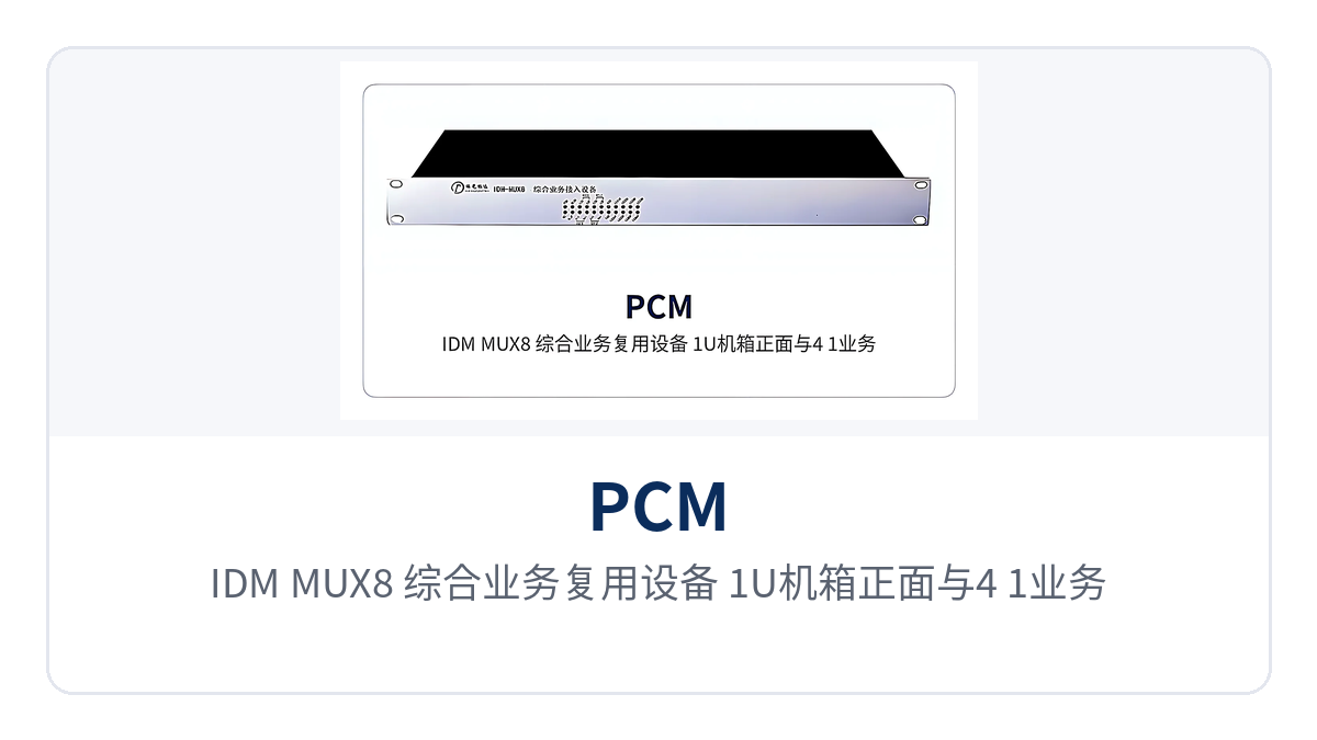
Figure 1: IDM MUX8 integrated service multiplexer 1U chassis front view and 4+1 service slot layout
What is the IDM MUX8?
The IDM MUX8 is an integrated service access device built around PCM multiplexing that integrates narrowband service access and E1 line transmission in a single 1U chassis. On one side, the device faces user interfaces such as FXS/FXO telephone, magneto, EM 2/4-wire audio, and RS232/RS422/RS485 serial ports; on the other side, it presents two E1 interfaces externally, and user services are loaded into 2.048Mbps E1 time slots within the device according to the PCM30/32 frame structure.
The general principle of a PCM multiplexer is to multiplex 64K voice and data services onto 2.048Mbps E1 channels for transmission according to the PCM30/32 frame structure. The E1 interface follows ITU-T G.703, uses HDB3 line coding, offers 75 Ω or 120 Ω impedance, uses the PCM30/32 frame structure, and adopts channel-associated signaling (CAS).
What problem does the device solve when one E1 reaches a site with mixed services?
Communication stations along power transmission lines, railway section equipment rooms, and underground electromechanical chambers in mines usually reserve only one E1 channel, yet the services to be connected on site include dispatch telephone, magneto telephone, audio trunk, and telecontrol serial port data. The IDM MUX8 implements these services on separate service cards inserted into the slots of the same 1U chassis, presenting only one or two E1 line interfaces externally; the interface layout shown in the product showcase also corresponds to this "many services, few lines" site form.
One device carries multiple types of services, so a site only needs to maintain one E1 line and one power supply, occupying 1U of cabinet space. When service types change or the number of channels increases, service cards can be replaced or added in the 4 slot groups or the expansion slot group, while the chassis, backplane, and existing E1 lines remain unchanged.
How the dual-E1 mutual backup PCM multiplexer is networked: mutual backup and time slot extraction modes
The dual E1 interfaces of the dual-E1 mutual backup PCM multiplexer have two operating modes, configured according to link conditions: mutual backup when there is only one reliable path, and time slot extraction when the two links belong to different directions or different services. A site first determines the mode according to service flow and the number of links, then allocates the time slots of service cards to the links.
What link conditions suit mutual backup mode?
In mutual backup mode, the two E1 lines carry the same set of services, one as primary and one as backup. When the primary link is interrupted or its bit error rate exceeds the usable range, services switch over to the backup link for continued transmission, and the site does not need to replace the device or reconfigure the service cards.
Mutual backup suits sites with a single service flow that demand high continuity, such as the dispatch telephone channel from a substation to a dispatch center. The two E1 lines usually come from two different transmission paths, and backup is meaningful only when the paths are separated; when both E1 lines run over the same optical cable or the same upstream device, the backup effect is offset by the common point of failure.
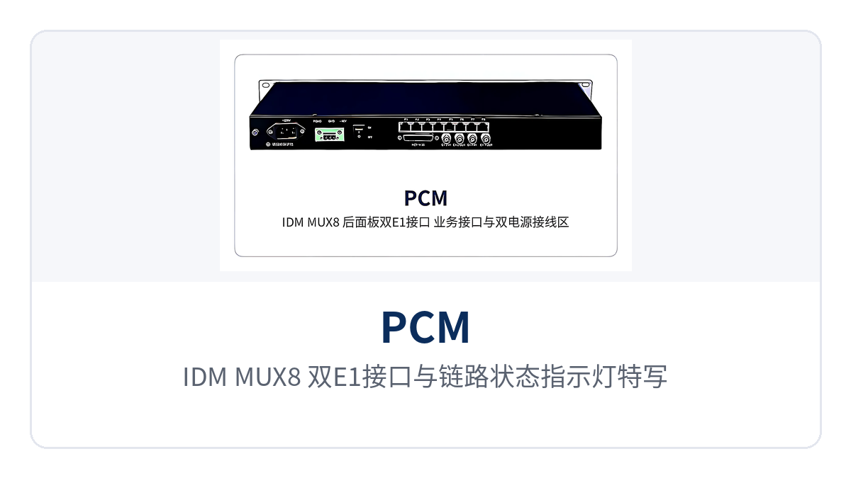
Figure 2: IDM MUX8 dual E1 interfaces and link status indicator LEDs close-up
How to choose mutual backup or time slot extraction for the two E1 lines
Whether to choose mutual backup or time slot extraction for the two E1 lines depends on whether the on-site service flows are in the same direction. If all services are sent to the same opposite end, choose mutual backup; if services are to be sent in two directions or to two types of systems, choose time slot extraction. The basis for the decision is the opposite end addresses in the service list, not link bandwidth or the number of interfaces.
In time slot extraction mode, the two E1 lines each carry allocated time slots, and the device extracts the required time slots from the two E1 lines for different services. One E1 line can be reserved for dispatch telephone while the other carries telecontrol data or image monitoring; services in both directions are allocated within the same device, so there is no need to configure a separate multiplexer for each direction.
In smart mining communication solutions, underground voice and monitoring data are sent to different systems, and time slot extraction mode fits exactly this type of service flow. During configuration, first count the number of voice channels and data channels required in each direction according to the service list, then calculate the time slot occupation of each E1 line, leaving margin for subsequent capacity expansion.
The E1 rate is 2.048Mbps, and the PCM30/32 frame structure provides 32 64K time slots per frame; synchronization and signaling take up part of them, and the available time slots are calculated channel by channel according to the number of service channels. When the number of service channels approaches the capacity limit of a single E1 line, services should be distributed across the two E1 lines to avoid having no time slots available for capacity expansion.
How to configure cards for 8 channels of 64K services with mixed insertion
To configure cards for 8 channels of 64K services with mixed insertion, first check the interface types in the on-site service list, then select service cards by type and insert them into the 4 slot groups or the expansion slot group. The slots of the same 1U chassis are shared by voice cards, audio cards, and data cards, and FXS, FXO, magneto, EM 2/4-wire, V.24, and RS232/RS422/RS485 services can be combined as needed.
The interface parameters corresponding to the service cards are listed in the table below. The audio range, compression, and impedance of audio service cards are marked according to the product documentation, and the rates and protocols of data service cards are listed as well. Parameters are subject to the product documentation, the specific configuration is determined by the project service list, and cards are selected in pairs at the transmit and receive ends.
| Service card type | Interface standards and parameters | Typical access objects |
|---|---|---|
| FXS | Audio 300 Hz to 3400 Hz, G.711 A-law, loop current 20 mA per channel | Analog telephone, fax machine |
| FXO | Audio 300 Hz to 3400 Hz, G.711 A-law, three-element complex impedance 200 Ω + 560 Ω//0.1 μF | Switch subscriber line, local exchange trunk |
| Magneto | Audio 300 Hz to 3400 Hz, balanced 600 Ω, return loss no less than 18 dB | Magneto telephone, dispatching exchange |
| EM 2/4-wire | Audio 300 Hz to 3400 Hz, balanced 600 Ω, G.711 A-law | Audio trunk, PA and amplification equipment |
| V.24 | Asynchronous ≤9600 bps, synchronous 64 Kbps, compliant with CCITT V.28 | Telecontrol terminal, serial port acquisition device |
| V.35 | n×64 Kbps (n=0–31), compliant with ITU-T V.35 and ISO2593 | Router WAN port, broadband data terminal |
When configuring cards, also verify the time slot occupation of each service channel and the interface type of the opposite end device, and configure service cards in pairs at the transmit and receive ends. 8 channels of 64K mixed insertion refers to the number of 64K service channels the device can provide, with the sum of voice and data service channels configured as 8; the specific number of insertable cards is determined by the number of slots in the chassis, and the 4+1 slots can be adjusted as services increase or decrease.
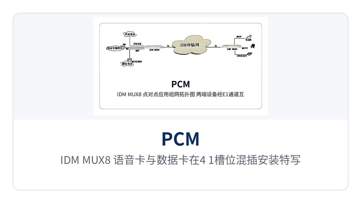
Figure 3: IDM MUX8 voice cards and data cards mixed insertion installation in 4+1 slots close-up
Core functions and performance specifications
The functions of the IDM MUX8 center on three items: dual E1 links, service access, and modular expansion. The function items and their purposes are listed in the table below. The function descriptions are summarized from the product documentation; during selection, compare them item by item against the service types actually required by the project, and function items not needed can be left unconfigured. As a PCM integrated service access device for multiple scenarios, the Raytrans IDM MUX8 can serve as a service access node in government private network optical fiber communication solutions, smart mining communication solutions, and military emergency communications vehicle solutions.
| Function | Description |
|---|---|
| Dual E1 transmission interfaces | Provides two E1 line interfaces at 2.048Mbps, HDB3 line coding, compliant with ITU-T G.703 |
| Link backup | The two E1 lines can be configured in mutual backup mode; when one link fails, services switch over to the other for transmission |
| Time slot extraction | The two E1 lines can be configured in time slot extraction mode, extracting time slots from the two links for allocation as services require |
| Multi-service mixed insertion | Provides 8 channels of 64K service interfaces, with optional FXS, FXO, magneto, common battery, EM 2/4-wire, and V.24 service cards |
| Modular structure | 19-inch 1U chassis, 4 service slot groups plus 1 expansion slot group, service cards configured as needed |
| Dual power supply | Power supply supports AC 220 V or DC -48 V, with optional dual power supply configuration |
| Interface conversion | Can be used as an interface converter to convert Ethernet, voice, V.35, V.24, and other services into E1 data streams |
| Channel extension | Suited to extending the working distance of interfaces over channels such as microwave and DDN private networks, expanding the service range |
The performance and interface parameters are listed in the table below, covering the E1 interface, various service interfaces, power supply mode, and operating environment. The parameters are subject to the product documentation; items marked with applicable conditions are used under those conditions, and where the project supply configuration differs from the documentation, the supply configuration sheet shall prevail.
| Item | Parameter/Specification | Description/Applicable Conditions |
|---|---|---|
| E1 bit rate | 2.048Mbps | HDB3 line coding, PCM30/32 frame structure, channel-associated signaling |
| E1 standard and impedance | Supports ITU-T G.703, impedance 75 Ω/120 Ω | Select 75 Ω coaxial or 120 Ω balanced according to the opposite end interface |
| Ethernet interface | RJ-45, N×VC12 (N≤50) | Supports IEEE802.3, full/half duplex/adaptive |
| Codirectional 64K interface | G.703 standard, 64 Kbps, balanced 120 Ω | Fully compliant with ITU-T G.703 |
| FXO/FXS audio | 300 Hz to 3400 Hz, G.711 A-law | Loop current 20 mA per channel, three-element complex impedance 200 Ω + 560 Ω//0.1 μF |
| EM 2/4-wire and magneto audio | 300 Hz to 3400 Hz, balanced 600 Ω | Return loss no less than 18 dB, compression G.711 A-law |
| V.24 interface | Asynchronous ≤9600 bps, synchronous 64 Kbps | Electrical characteristics compliant with CCITT V.28 |
| V.35 interface | n×64 Kbps (n=0–31), RJ-45 | Compliant with ITU-T V.35, terminal interface compliant with ISO2593 |
| Power supply mode | AC 220 V/DC -48 V | Optional dual power supply configuration, suited to AC equipment rooms and DC sites |
| Overall power consumption | ≤150 W | Upper limit of overall power consumption, calculated with full configuration of service cards |
| Operating environment | Temperature -10℃ to +50℃, humidity 0–95% (non-condensing) | Suited to equipment rooms, station buildings, and vehicle-mounted cabinets |
| Product dimensions | 220×141×39 mm | 19-inch 1U standard chassis structure |
The correspondence between the three differentiated capabilities and on-site value is listed in the table below; the left column shows the capabilities of the device, and the right column shows the specific problems these capabilities solve at a site. During selection, check them item by item against site conditions; capability items not needed can be left unconfigured, and the specific board configuration is subject to the commercial confirmation sheet.
| Differentiated selling points | Value on site |
|---|---|
| Dual E1 mutual backup | When one link fails, services are automatically switched to the other link, and sites with different service flows can share one device |
| 4+1 slot mixed insertion of 8-channel 64 kbit/s services | One unit replaces multiple single-service converters, reducing both the number of devices in the cabinet and the amount of wiring on the user side |
| AC220V/DC-48V dual power supply options | AC and DC sites share the same model and spare parts, so AC equipment rooms and DC power supply sites do not need to stock two models |
How to Wire a Dual Power Supply PCM Device
How to wire a dual power supply PCM device: select according to the power supply conditions of the site. Use an AC220V power supply module when the equipment room has an AC distribution panel, and a DC-48V power supply module at DC power supply sites; when both conditions are available, dual power supplies can be configured. The power supply module is installed inside the device, with only wiring terminals exposed. Before wiring, check the output voltage and capacity of the distribution panel.
With a dual power supply configuration, two power feeds are connected at the same time. When one feed loses power, the other continues to supply power and services continue. During wiring, the two power feeds are led in from different distribution circuits. If both feeds are taken from the same circuit breaker, tripping the breaker will cut off both power feeds at the same time.
Power supply and environmental parameters are AC220V or DC-48V power supply, overall power consumption ≤150 W, operating temperature -10℃+50℃, and relative humidity 095% (non-condensing). The 19-inch 1U chassis can be installed directly in a standard cabinet and occupies 1U of height. AC and DC models have the same appearance and installation method, and spare parts are shared between sites. In government private network optical fiber communication solutions, smart mining communication solutions, and military emergency communications vehicle solutions, this Raytrans PCM equipment series can be deployed flexibly based on the above dual power supply and product showcase configurations.
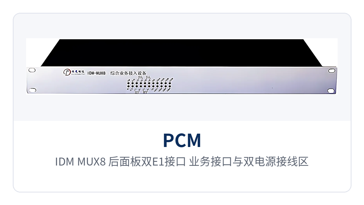
Figure 4: IDM MUX8 rear panel dual E1 interfaces, service interfaces, and dual power supply wiring area
Typical Application Scenarios
The IDM MUX8 PCM multiplexer targets private network sites with limited channel resources and a mix of service types. The differences across the three industries lie mainly in the dual E1 working mode and the combination of service cards. The networking topology is point-to-point in all cases: one device at each end, connected by an E1 channel in between, with services configured symmetrically at both ends.
For different industry requirements, Raytrans has developed a government private network optical fiber communication solution, a smart mining communication solution, and a military emergency communications vehicle solution based on the IDM MUX8. The three solutions share the same product showcase configuration; the differences lie in service card selection and the working mode of the two E1 channels.
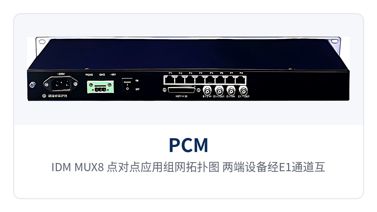
Figure 5: IDM MUX8 point-to-point application networking topology, with devices at both ends interconnected through an E1 channel and connected to voice and data services
Electric Power Private Network: Dispatch Telephone and Telecontrol Data Carried by One Device at a Substation
Between a substation and the dispatch center there are usually two types of services, dispatch telephone and telecontrol data, with one or two E1 channels provided by transmission equipment. As an integrated service access device, the IDM MUX8 uses FXS/FXO cards to connect dispatch telephones and switch subscriber lines, and V.24 or RS232 cards to connect telecontrol terminals, multiplexing both service types onto the E1 channel to the dispatch center.
When the dual E1 channels are configured for mutual backup, services are switched to the other link after one link is interrupted, so dispatch telephone and telecontrol data do not lose their path at the same time due to a single link failure. The optional dual power supply configuration matches the AC and DC power supply conditions of the substation, so the station does not need to stock two models for different power supply modes.
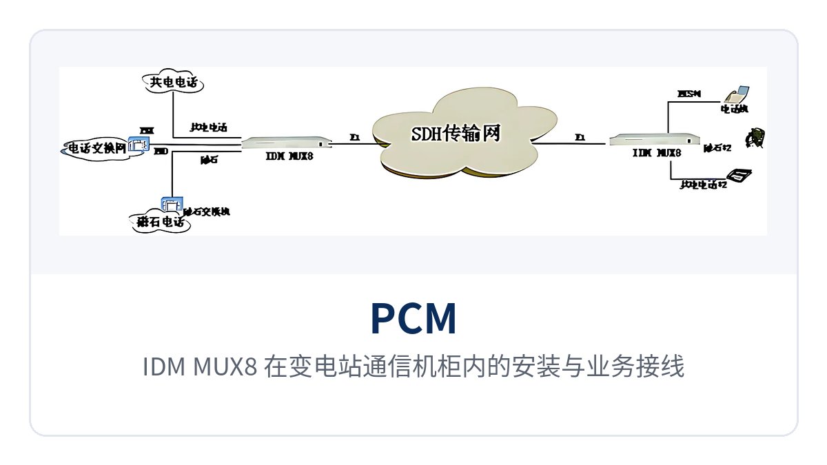
Figure 6: IDM MUX8 installation and service wiring in a substation communications cabinet
Smart Mining: Underground Voice and Monitoring Data Sent to Different Systems
The channel between the underground mine and the surface is usually provided by optical transmission equipment, and underground sites need to connect dispatch telephones, broadcast audio, and safety monitoring data at the same time. The IDM MUX8 uses magneto and EM2/4-wire cards to connect underground broadcast and dispatch telephones, and serial port cards to connect monitoring substation data. Both service types are mixed and inserted in the same 1U device, meeting the requirement of the Raytrans smart mining communication solution for underground multi-service aggregation.
Underground voice goes to the dispatch center and monitoring data goes to the safety monitoring system. The opposite ends differ in the two directions, so the two E1 channels are configured in time slot extraction mode, each carrying its assigned time slots. One device meets the access requirements of both systems and avoids placing multiple single-service converters side by side next to the cabinet in the underground electromechanical chamber.
The device operates at -10℃+50℃ and 095% humidity (non-condensing), and can be installed in both underground electromechanical chambers and surface equipment rooms. The 8-channel 64 kbit/s service channels are configured according to the underground service list; when monitoring points are added later, cards can be added in the expansion slots, while the existing E1 channel and wiring remain unchanged.
Military and Government Private Network: E1 Extension and Link Backup in a Vehicle-Mounted Cabinet
Military and government private networks have many user interface types and inconsistent line sources, with E1 channels commonly provided by microwave, DDN private networks, and optical transmission equipment. The IDM MUX8 can serve as an interface converter, converting services such as 10/100Base-T Ethernet, voice, V.35, and V.24 into E1 data streams, extending the working distance of the interfaces over existing channels and meeting the multi-interface access requirements of the military emergency communications vehicle solution.
When setting up a channel between an emergency communications vehicle and a fixed station building, one device is placed at each end, and the cabinet in the vehicle needs only 1U of space to mix and insert telephone, audio, and data services. When the two E1 channels belong to different transmission paths, they are configured for mutual backup; after one path is interrupted, services are carried by the other, with link backup and service access completed in the same device.
Figure 7: IDM MUX8 installation and interface routing in an emergency communications vehicle-mounted cabinet