
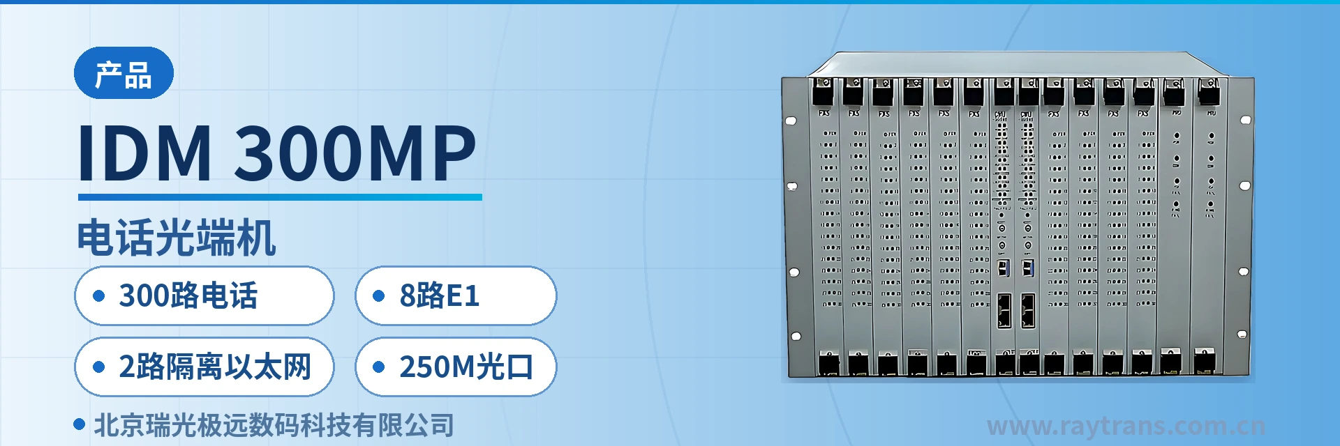
IDM-300MP Telephone Optical Multiplexer
300-channel telephone 8E1 dual isolated 100M same-fiber 14-slot hot-swappable dual main control dual
The IDM-300MP multi-service optical multiplexer provides a 250M optical interface, 300 telephone channels + 8E1 + 2 physically isolated line-rate 100M Ethernet channels, and a standard SNMP network management interface.
The IDM-300MP 300-channel telephone multi-service optical multiplexer is a centralized PCM optical fiber transmission device developed by Beijing Ruiguang Jiyuan Digital Technology Co., Ltd. It consists of a 250Mbps SFP optical port, a 14-slot chassis and service cards, and is used to simultaneously carry 300 voice channels, 8 E1 channels and 2 physically isolated 100M Ethernet channels over a single optical fiber. As a professional optical multiplexer manufacturer, Raytrans has continued the consistent centralized design approach from its product showcase in this product, giving this multi-service optical multiplexer high port integration among comparable telephone optical multiplexers.
The device targets site aggregation scenarios in electric power private networks, rail transit, and military and government private networks, gathering dispatch telephones, E1 leased lines and in-station data into a single 6U chassis, so that an access node does not need a separate optical multiplexer for each service type. Fully configured with 10 service cards at 30 voice channels each, the main control cards and power supplies are configured in 1+1 mutual backup, and all card slots support hot-swappable operation. For users requiring a government private network optical fiber communication solution, this PDH optical multiplexer can serve as the core transmission unit at the site aggregation layer; in a military emergency communications vehicle solution, its compact 6U chassis and multi-service carrying capability likewise facilitate rapid deployment.
Key Specifications at a Glance: 300 voice channels · 8 E1 channels · 2 physically isolated 100M Ethernet channels · 250Mbps SFP optical port · receiver sensitivity better than -36dBm · 14-slot 6U chassis
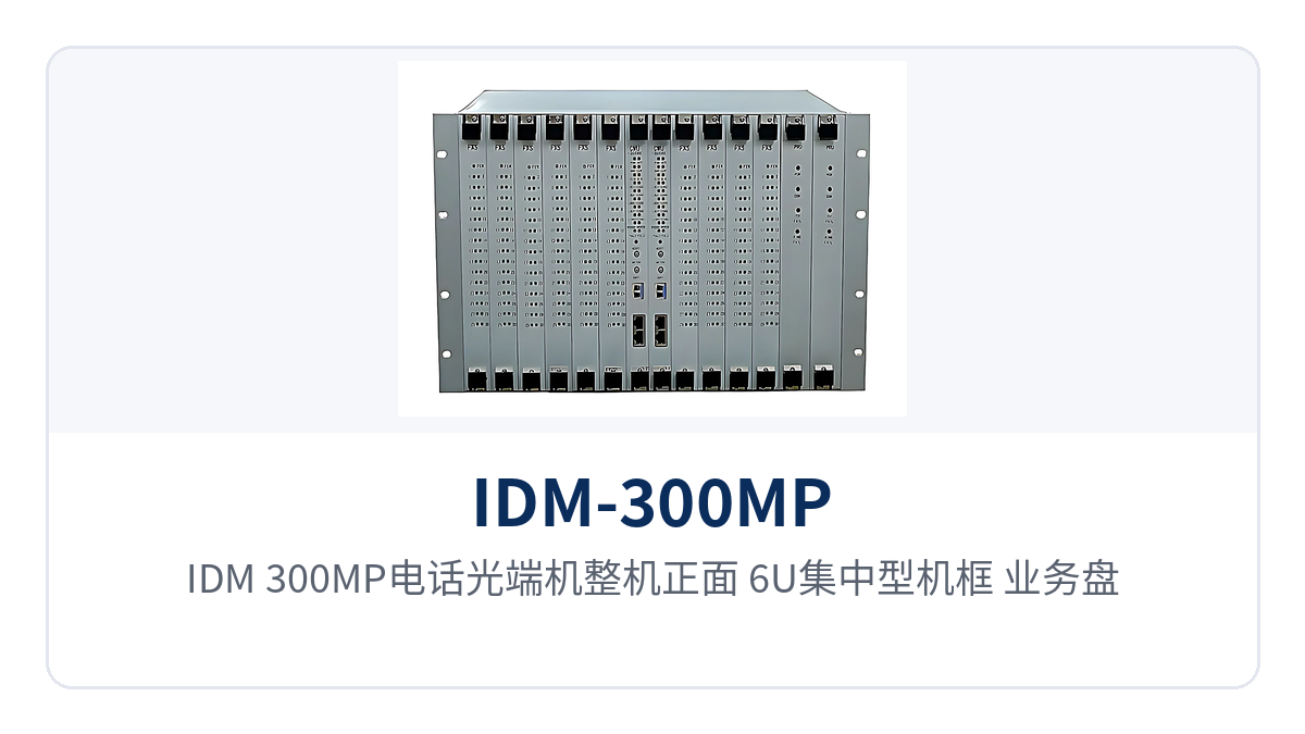
Figure 1: Front view of the IDM-300MP telephone optical multiplexer — close-up of the 6U centralized chassis, service card slots and optical link alarm indicator LEDs
What Is a 300-Channel Telephone Multi-Service Optical Multiplexer
A 300-channel telephone multi-service optical multiplexer is a centralized transmission device that multiplexes narrowband voice, E1 leased lines and Ethernet data onto the same optical fiber, with a 250Mbps optical port on the line side and FXO/FXS voice channel interfaces, E1 interfaces and RJ-45 Ethernet ports on the tributary side. As a typical multi-service optical multiplexer, the IDM-300MP organizes voice channels in PCM30/31 format; one unit is placed at each end, with one end performing access and the other end restoring the signals.
Inside the device, voice is encoded into digital voice channels at 64Kbps, with each channel using ITU-T G.711 A-law compression, an audio range of 300Hz to 3400Hz, and a loop current of 25mA per channel. The 8 E1 channels are transparently transmitted at a 2048Kbps bit rate in HDB3 code, compliant with ITU-T G.703, without changing the original time slot content within the frame, and can be directly connected to existing PCM equipment and SDH tributaries.
How the 250M Optical Port and 8 E1 Channels Share One Fiber
The 250Mbps optical line packs the 300 64K voice channels, 8 E1 channels and 2 isolated Ethernet channels delivered by the 10 service cards into the same transmission frame, with each service type occupying independent time slots. Commissioning a single optical path completes the multi-service uplink of the entire site, and the number of fiber cores occupied between stations decreases along with the number of devices.
Services and network management travel over two mutually isolated channels: one RJ-45 carries service data, while the other is reserved for SNMP network management and maintenance terminals, so the network management channel remains connected even during service traffic bursts. The two ports are physically isolated inside the device, so a broadcast storm on one side will not propagate to the other.
How 14 Slots Deliver 300 Voice Channels: Card-Based Structure
Each service card provides 30 channels of 64K telephone audio service, and 10 service cards fully populated reach 300 subscriber voice channels — the direct reason a single device can handle 300 lines. Slots are configured card by card, and capacity expansion only requires adding cards without changing the chassis or external cabling, which is also the common card configuration for 300-channel telephone optical multiplexers at traffic-intensive sites.
The unit provides 14 slots, configured with 10 service cards and 2 main control cards, plus a CMU central control and management card and power cards. The 2 main control cards support mutual backup, and the power supplies are configured in 1+1 mutual backup, so services continue running if either main control card or power supply unit fails; all slots support hot-swappable operation, so replacing a service card does not require powering down the entire unit.
FXO and FXS interfaces are selected by direction: FXO connects to exchange-side resources such as switches and SPC switching equipment, while FXS directly connects to subscriber terminals such as telephones and fax machines; both interface types support caller ID (CID). Different directions of service cards can be mixed in the same device, so line provisioning and access are completed in a single configuration.
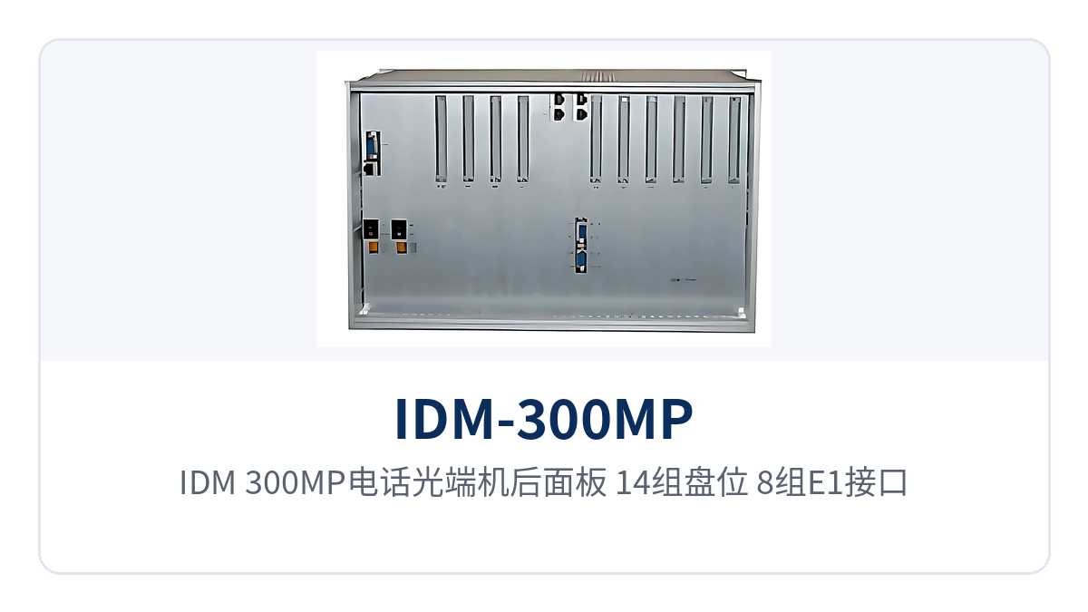
Figure 2: Rear panel of the IDM-300MP telephone optical multiplexer — layout of 14 slots, 8 E1 interfaces, 2 RJ-45 Ethernet ports and power supply terminals
How to Check the Key Specifications: Optical Port, E1, Ethernet and Power Supply
Specifications are listed in five groups: optical interface, Ethernet, E1, voice channels and power supply environment. The check sequence is to first calculate the link optical power budget, then count the voice channel directions and E1 channels, then confirm the division of labor between the 2 Ethernet channels, and finally determine the power supply format according to the equipment room power conditions.
Optical Interface and Ethernet Interface
| Item | Parameter/Specification | Description/Applicable Conditions |
|---|---|---|
| Optical interface type | SFP | Pluggable optical module, replaceable by distance and wavelength, with common spares |
| Fiber mode | Single-mode (multi-mode optional) | Selected according to on-site optical cable and link distance |
| Optical fiber rate | 250Mbps | Telephones, E1 and Ethernet share this optical line |
| Wavelength | 850nm/1310nm/1550nm | Wavelength and interface type paired at both ends |
| Transmit optical power | -2 to -11dBm | Available transmit-side optical power range |
| Receiver sensitivity | Better than -36dBm | Receive threshold for weak optical links, used to calculate the power budget |
| Ethernet interface | RJ-45, 2 channels | 100M line rate, 10M/100M adaptive |
| Ethernet standard | Compliant with IEEE-802.3u | Directly connected to conventional switching equipment |
| Ethernet isolation mode | 2 physically isolated channels | One for services, one for network management, with independent bandwidth and broadcast domains |
| Network management interface | SNMP | Operating status and alarms integrated into the existing network management system |
| Transmission distance | Calculated by optical module and link attenuation | No fixed distance figure is available in the knowledge base here |
E1 Interface and FXO/FXS Voice Channel Interface
| Item | Parameter/Specification | Description/Applicable Conditions |
|---|---|---|
| Number of E1 channels | 8 (4 groups of 75Ω unbalanced, 4 groups of 120Ω balanced) | Coaxial or balanced interfaces selected according to on-site cabling conditions |
| Bit rate | 2048Kbps | Standard E1 line rate |
| Code | HDB3 | Compliant with ITU-T G.703 |
| Impedance | 75Ω/120Ω | Matched to the E1 interface of the connected device |
| Frame structure | PCM30/31 | 32 time slots per frame, 30 time slots carrying services |
| Transmission mode | Transparent transmission | Does not change the original time slot content within the frame |
| Voice channel capacity | 300 channels | 10 service cards, 30 64K voice channels each |
| Voice channel interface | FXO/FXS | FXO for the exchange side, FXS for telephones, with caller ID (CID) support |
| Audio range | 300Hz to 3400Hz | Telephone voice channel frequency band |
| Compression | ITU G.711 A-law | 64Kbps encoding per channel |
| Voice channel impedance | Three-element complex impedance 200Ω+560Ω//0.1μF | Matched to PSTN subscriber line characteristics |
| Loop current | 25mA per channel | Feeding capability of each voice channel |
Power Supply, Power Consumption and Installation Environment
| Item | Parameter/Specification | Description/Applicable Conditions |
|---|---|---|
| Power supply mode | DC-48V/AC220V (external) | Two power supply access options: DC distribution panel and AC mains power |
| Overall power consumption | ≤400W | Unit value with fully populated service cards and optical modules |
| Operating temperature | 0℃ to +40℃ | Communications equipment room and equipment room environment |
| Humidity | 90% (35℃) non-condensing | Normal operation under non-condensing conditions |
| Dimensions | 482×266×270 (mm) | Length×Depth×Height, 19-inch standard 6U chassis |
| Chassis color | Black/white optional | Specify at ordering according to equipment room color scheme |
| Slots | 14, all hot-swappable | 10 service cards, 2 main control cards, management card and power cards |
Unit Functions at a Glance
Functions are arranged in four categories: access, transmission, redundancy and O&M. Each item corresponds to a specific on-site action; during configuration, check each item in the table one by one to avoid missing voice channel directions, E1 interface forms or Ethernet channels. The items in the table correspond one-to-one with the ordering list, so technical and commercial checks can copy them directly.
| Function | Description |
|---|---|
| 300-channel telephone access | 10 service cards each provide 30 64K voice channels, fully populated to 300 FXO/FXS channels, with caller ID (CID) support |
| 8-channel E1 transparent transmission | 4 groups of 75Ω unbalanced and 4 groups of 120Ω balanced, 2048Kbps, HDB3, compliant with ITU-T G.703, transparently transmitted as-is |
| 2 isolated Ethernet channels | 2 RJ-45 ports, 100M line rate, 10M/100M adaptive, compliant with IEEE-802.3u, physically isolated from each other |
| 250M optical transmission | SFP optical port, 250Mbps line rate, single-mode with multi-mode optional, wavelengths 850nm/1310nm/1550nm selectable |
| Hot-swappable slots | Service cards, main control cards and power cards can be replaced online; expansion only requires adding cards without changing the chassis or cabling |
| Main control and power redundancy | 2 main control cards in mutual backup and 1+1 mutual backup power supplies; services continue running if a single card or single power supply fails |
| SNMP network management | Standard SNMP network management interface, with operating status and alarms integrated into the existing network management system |
| Centralized chassis | 19-inch standard 6U chassis, consistent with installation practices in telecommunications and carrier equipment rooms |
Differentiated Value: Three Capabilities Addressing Three Types of On-Site Problems
Site expansion commonly faces three types of problems: multiple services each occupying their own device and fiber cores, excessive optical cable attenuation preventing commissioning, and services and network management competing for the same Ethernet channel. The three capabilities of the Raytrans IDM-300MP multi-service optical multiplexer address these three problems respectively, hold true simultaneously at electric power, rail transit and private network sites, and provide a clear reference for selecting multi-service optical multiplexers in the product showcase.
| Differentiation Point | Customer Value |
|---|---|
| 300 voice channels, 8 E1 channels, 2 isolated Ethernet channels | Multi-service aggregation in a single unit: voice, leased lines and data are accessed and uplinked within one 6U chassis, so a site does not need to cascade multiple single-function devices |
| 250Mbps optical port, sensitivity better than -36dBm | Stable transmission even over weak optical links: calculated from the -11dBm lower transmit optical power limit and the -36dBm receive threshold, the available link attenuation is about 25dB, leaving margin for sections with more splice points |
| 2 physically isolated 100M line-rate Ethernet channels | Service and network management channels do not interfere with one another: data and network management each use their own channel, service bursts do not squeeze the network management channel, and troubleshooting does not require competing for bandwidth |
Typical Application Scenarios
The three types of sites differ in traffic density, link conditions and power supply mode, yet the configuration approach can follow the same sequence: first determine voice channels, then E1 and Ethernet, and then the power supply format. Checking the list site by site with the same method also unifies spares and O&M approach; when the number of in-station interfaces changes, only the service card configuration is adjusted. As a professional optical multiplexer manufacturer, Raytrans can directly reuse the card configuration experience accumulated on its telephone optical multiplexer and PDH optical multiplexer product lines in the following scenarios.
Electric Power Private Network: One Fiber Aggregates 300 Voice Channels and 8 E1 Channels, Saving Fiber Cores for Multi-Service Uplink at Substations
Between substations and dispatch centers, both dispatch telephones and telecontrol, metering and monitoring data are carried. The IDM-300MP aggregates 300 voice channels, 8 E1 channels and 2 isolated Ethernet channels within the station and sends them to the dispatch center over a single 250Mbps optical fiber, reducing the number of incoming optical cables and cabling along with the number of devices — a typical configuration at the substation access layer in a government private network optical fiber communication solution.
Most sites are unattended. The -48V DC distribution panel in the station can connect directly to the DC-48V power supply. The overall power consumption of the unit is ≤400W, and cabinet power supply access and heat dissipation are reserved according to a full configuration of service cards. When a new interval is added, only the service card and management card configuration is added, while the chassis and external wiring remain unchanged. Inspection is judged by front panel alarms and SNMP reports.
Rail Transit: 250M Optical Port Plus 2 Physically Isolated Ethernet Interfaces, with Communication and Service Channels Separated
The official telephones, PA control and monitoring data of stations along the line, trackside equipment rooms and depots need to be aggregated at the central side. The device uses point-to-point networking to put the inter-station voice channels and E1 channels onto a single optical path. Of the 2 Ethernet interfaces, one carries monitoring and office data, and the other is reserved for network management, so the communication channel and the service channel do not affect each other.
Sections have many optical cable splice points and relatively high link attenuation. The receiver sensitivity of better than -36dBm leaves power margin for weak optical links. Before enablement, reserve more than 3dB of margin based on the received optical power measured with an optical power meter. Service cards in the station are configured according to the number of interfaces: stations with heavy traffic are fully populated with service cards, and stations with many monitoring points are additionally equipped with Ethernet-side devices.
Military and Government Private Networks: 300 Telephone Channels, 8E1 and 2 Isolated Ethernet Interfaces, One Device Supporting a Multi-Service Private Network Node
Temporary command posts, vehicle-mounted racks and fixed equipment rooms differ greatly in traffic and interface types. The device adapts in a card-based manner: when traffic is concentrated, service cards are fully populated to provide 300 telephone channels; when dedicated lines are needed, 8 E1 interfaces are fully populated; when data is needed, 2 isolated Ethernet interfaces carry it separately. The 19-inch 6U chassis fits into a standard cabinet. For mobile deployment, the hoisting and wiring workload decreases with the number of devices, meeting the requirements of the military emergency communications vehicle solution for rapid deployment and multi-service carrying.
The two power supply modes of DC-48V and AC220V (external power supply) cover the two on-site conditions of DC distribution panel and mains power. Sites draw power from the existing power supply and do not need to install an inverter for the device. The main control card and power supply have 1+1 mutual backup, and the card slots are hot-swappable. Replacing a single card on site restores services, and O&M does not require returning the complete unit to the factory.
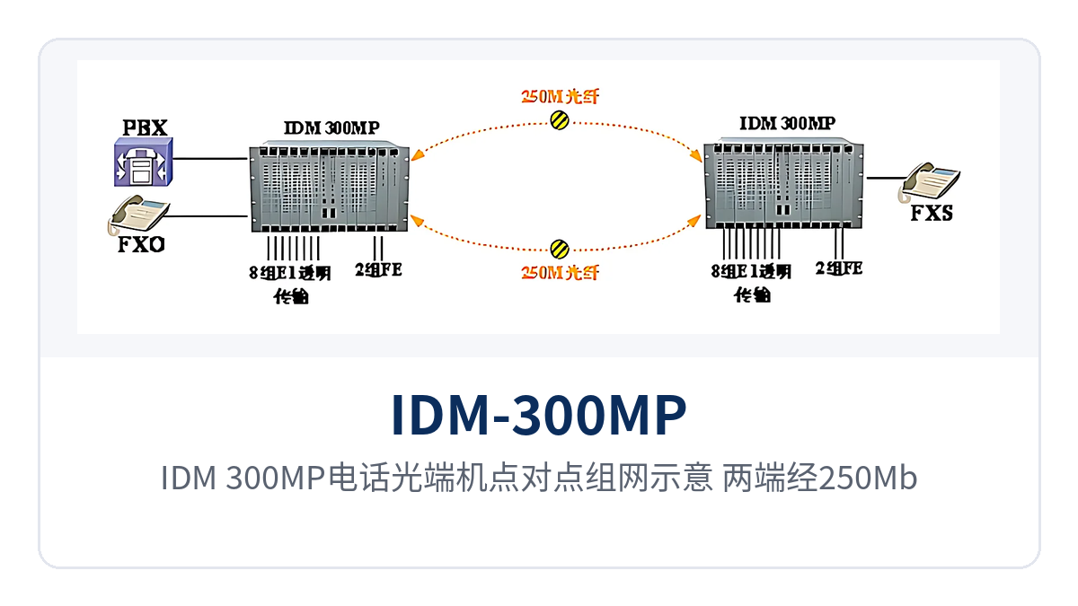
Figure 3: IDM-300MP telephone optical multiplexer point-to-point networking schematic. Both ends are interconnected via 250Mbps SFP optical ports, terminating telephone, E1 and isolated Ethernet services
Conclusion
As a 300-channel telephone multi-service optical multiplexer, the selection focus of IDM-300MP is straightforward: first determine the service cards according to voice channel direction and quantity, then configure interfaces according to E1 direction and Ethernet isolation requirements, and then select DC-48V or AC220V power supply according to the equipment room power conditions.
The device packs 300 telephone channels, 8 E1 interfaces and 2 isolated Ethernet interfaces into a single 6U chassis. With 1+1 mutual backup of the main control and power supply, it is suitable for medium and large access nodes of electric power, rail transit, and military and government private networks. As an optical multiplexer manufacturer, Raytrans can provide specific card configuration and optical module selection recommendations based on the actual survey data of government private network optical fiber communication solutions and military emergency communications vehicle solutions. It is recommended to confirm with the manufacturer's technical team during the survey phase.


