IDM-120P 128-Time-Slot Cross-Connect PCM Multiplexer
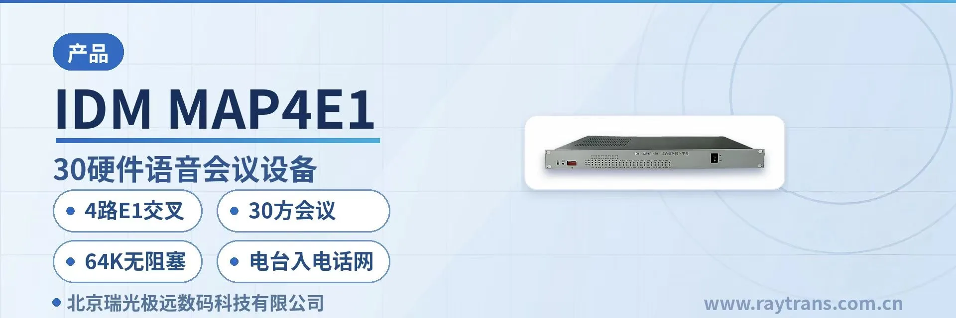
4xE1 full time-slot scheduling, two-stage cross-connect from subscriber to line, saving one standalone cross-connect at the access site
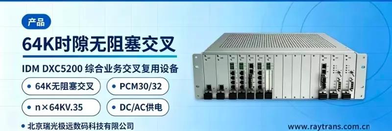
The IDM-120P integrated service cross-connect multiplexer uses a standard 19-inch 1U chassis and is a PCM multiplexer that processes up to 4 E1 signals; it has 8 universal slots and 2 expansion slots; it can provide 16 channels of 64K plus 8 channels of n×64K subscriber interfaces and can be flexibly configured with more than 20 types of interface cards as required;
The IDM-120P 128-time-slot cross-connect PCM multiplexer is a rack-mounted PCM multiplexer developed by Beijing Ruiguang Jiyuan Digital Technology Co., Ltd. (Raytrans). It performs 4xE1 signal processing with a dedicated large-scale integrated circuit and multiplexes services such as telephony, data, and Ethernet onto E1 or optical fiber channels for transmission. The device targets voice, data, and video surveillance dedicated line access for electric power, public security, and financial systems, covering both narrowband services and Ethernet services, and is a commonly used integrated service access device in government private network optical fiber communication solutions.
The device uses a standard 19-inch 1U chassis, with 8 universal slots and 2 expansion slots inside. The subscriber interface capacity is configurable within the range of 16 channels of 64K and 8 channels of n×64K. More than 20 types of interface cards are available, with more than 30 subscriber interface types in total, which can be combined according to the on-site service list, meeting the diverse product showcase requirements of narrowband and broadband integrated service access.
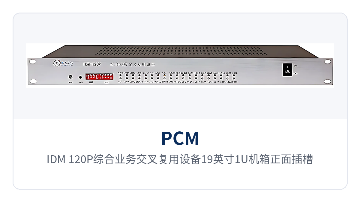
Figure 1: Front slot layout and operating indicator LEDs of the 19-inch 1U chassis of the IDM-120P Integrated Service Cross-Connect Multiplexing Equipment
Key Specifications at a Glance: 4xE1 · 128-time-slot cross-connect · 16 channels of 64K + 8 channels of n×64K · 8 universal slots + 2 expansion slots · dual power supply and dual ringing current backup · RS232/RS485 network management
What is a 128-time-slot cross-connect PCM multiplexer?
The IDM-120P 128-time-slot cross-connect PCM multiplexer concentrates narrowband service access, E1 multiplexing, and time-slot cross-connection in the same 1U chassis: one side accesses E1 lines in 4 directions, and the other side provides voice and data interfaces. After services enter the chassis, they are first split into 64K time slots, and then scheduled by the built-in 128-time-slot cross-connect matrix to the target E1 direction according to the configuration. The whole product showcase revolves around the three stages of access, multiplexing, and cross-connection.
Access, multiplexing, and cross-connection are completed within the same device, so an access site no longer needs to cascade a separate time-slot cross-connect equipment. For private networks with many sites and frequently adjusted service assignment, one less equipment level means one less point of failure and one less set of cabinet wiring.
In addition to E1, the chassis can also accommodate PDH optical interface modules, providing 4 channels of 100M Ethernet and 4 optical directions as an optical multiplexing equipment. Broadband and narrowband services therefore share the same chassis and are multiplexed over E1 copper cables or optical fiber, forming an integrated service access device platform that combines PCM multiplexing and Ethernet access, and is suitable for voice, data, and video surveillance dedicated line access scenarios in government private network optical fiber communication solutions.
What can this PCM multiplexer do: core functions at a glance
The functions of the IDM-120P 128-time-slot cross-connect PCM multiplexer cover four levels: service access, time slot scheduling, alarms, and network management. See the table below for details, which facilitates checking the configuration against the on-site service list and synchronizing optional items with the commercial process.
| Function | Description |
|---|---|
| 4xE1 receive/transmit | Provides E1 line receive/transmit in 4 transmission directions, with a single chip performing 4xE1 signal processing, and can interconnect with transmission equipment and existing PCM equipment |
| 128-time-slot cross-connection | Built-in 128-time-slot cross-connect matrix supports two-stage cross-connection, realizing user-to-user, user-to-line, and line-to-line data and signaling interconnection |
| Multi-service multiplexing | Voice, 64K codirectional, V.24/V.35 data, and 10BASE-T Ethernet services are multiplexed into E1 time slots, so one E1 carries voice and data simultaneously |
| Flexible card configuration | 8 universal slots plus 2 expansion slots, configurable with more than 20 types of interface cards, with more than 30 subscriber interface types in total |
| Multi-timeslot data channel | Built-in 4 multi-timeslot card channels, can accommodate V.35 (n×64K) and 10BASE-T cards, and can also provide high-speed asynchronous RS232/RS485 |
| Clock and interface compatibility | Supports master clock, external clock, line clock, and user clock; can be set as exchange interface or subscriber interface, compatible with both central office and remote end |
| Optical fiber and Ethernet expansion | PDH optical interface modules can be inserted, providing 4 channels of 100M Ethernet and 4 optical directions, with broadband and narrowband services multiplexed in the same chassis |
| Monitoring and alarm | Emits an audible alarm when the E1 state changes, with panel indicator LEDs showing the specific alarm state and rack alarm information output simultaneously |
| Network management | Provides RS232 and RS485 network management interfaces, supporting configuration, query, and fault statistics management; RS485 can cascade multiple devices |
| Power supply and ringing current backup | Dual power supply and dual ringing current modules operate in half-power mode, and the unit continues to work normally when a single module fails |
How do 4xE1 and 128-time-slot cross-connection work?
The basis of 4xE1 time-slot cross-connection is the PCM30/32 frame structure: each E1 transmits at 2.048Mbps, and each frame is divided into 32 time slots, of which TS0 is used for frame alignment and alarms, TS16 carries channel-associated signaling (CAS), and the remaining 30 time slots carry 64K services. The interface follows the ITU-T G.703 standard.
Knowledge block: what 128-time-slot cross-connection means. 128-time-slot cross-connection means the cross-connect matrix can simultaneously handle the connection relationships of 128 64K time slots, exactly corresponding to the sum of the 32 time slots of 4xE1, with all time slots included in scheduling; any input time slot can be configured to any output time slot, and the connection relationships are delivered by configuration without relying on manual patch cords.
Cross-connection is divided into two stages: one stage establishes the mapping between subscriber interfaces and time slots, and the other schedules between time slots and E1 lines. The two stages together complete the three types of interconnection—user-to-user, user-to-line, and line-to-line—so services across E1 directions can be transferred directly locally.
This mechanism enables the IDM-120P Integrated Service Cross-Connect Multiplexing Equipment to serve both multiplexing and cross-connection purposes. When time slots need to be reallocated among the 4 E1 directions, the device is used as a time-slot cross-connect equipment for 4xE1; when only point-to-point multiplexing is required, the cross-connect matrix can be configured with fixed mapping.
Technical specifications and interface configuration
The structure and line parameters of the device are shown in the table below; the power supply voltage levels, overall power consumption, and operating temperature and humidity ranges are not listed in the available product documentation, and the technical documentation supplied with the unit and confirmation with the manufacturer shall prevail during selection. The interface quantities in the table are given on a full-configuration basis for the complete unit, and the actual number of usable channels depends on the capacity of the selected interface cards.
| Item | Parameter/Specification | Description/Applicable Conditions |
|---|---|---|
| Chassis structure | 19-inch 1U standard chassis | Can be installed in a standard cabinet; desktop use requires an additional tray |
| Slot configuration | 8 universal slots + 2 expansion slots | Universal slots take service interface cards; expansion slots take optical interface and other modules |
| E1 line directions | 4 transmission directions | One E1 receive/transmit per direction, can connect to transmission equipment or the opposite multiplexer |
| E1 frame structure and rate | PCM30/32, 2.048Mbps | Follows the ITU-T G.703 standard; interface form configured according to the live network line |
| Cross-connect matrix capacity | 128 time slots | All 32 time slots of 4xE1 are included in cross-connection scheduling |
| Subscriber interface capacity | 16 channels of 64K + 8 channels of n×64K | Configured by card combination; 24 channels of subscriber services can be transmitted in 4 E1 directions |
| Interface card type | More than 20 available | More than 30 subscriber interface types in total, combined according to the service list |
| Ethernet expansion | 4 channels of 100M Ethernet + 4 optical directions | Provided after inserting PDH optical interface modules; broadband and E1 services in the same chassis |
| Clock mode | Master clock/external clock/line clock/user clock | Can be set as exchange interface or subscriber interface, compatible with both central office and remote end |
| Network management interface | RS232 / RS485 | RS485 can cascade multiple devices, with rack alarm output |
| Power supply and ringing current | Dual power supply, dual ringing current modules | Operate in half-power mode; the unit continues to work when a single module fails |
| U interface trunk transmission | 5–7 km over twisted pair | Uses 2B1Q encoding, carrying V.35, 10BASE-T, V.24, X.21, and 64K codirectional services |
How to configure more than 30 subscriber interfaces: mixed voice, data, and Ethernet connections
Interfaces are divided into three groups by service type: voice, data, and Ethernet. Each group is selected as needed from the list of more than 20 interface cards, and after being inserted into the same chassis, time slots are uniformly allocated by the 128-time-slot cross-connect matrix. One device can therefore simultaneously handle narrowband and broadband integrated service access, meeting the hybrid networking requirements of voice, data, and video surveillance dedicated line access.
| Interface category | Available interfaces | Carried services and description |
|---|---|---|
| Conventional voice | FXO, FXS, polarity reversal and caller ID (CID) telephone | Connects to exchange subscriber lines or remote telephones, supporting caller ID and polarity reversal |
| Specialized voice | Magneto, 2100 Hz carrier magneto, hotline, carrier, EM 2/4-wire audio, high-fidelity audio | Used for dispatch telephone, public address (PA), and dedicated liaison voice channels |
| Signaling and switching | Signaling System No. 1 card, telephone switching card, baseband trunk interface card | Interconnects with existing switching equipment, completing signaling interworking and internal switching |
| Low-speed data | V.24/V.28 (RS232/RS485), 64K codirectional | Carries low-speed data such as telecontrol, monitoring, and meter reading, and synchronous 64K services |
| High-speed data | V.35 (n×64K), DTE and DCE modes selectable | Carries n×64K synchronous data services such as router WAN ports |
| Ethernet | 10BASE-T card, multi-timeslot card channels | Provides Ethernet access with n×64K bandwidth, and can also be used as high-speed asynchronous RS232/RS485 |
Voice and data can coexist in different time slots of the same E1: a voice channel occupies one 64K time slot, V.35 services occupy consecutive time slots as needed, and Ethernet takes bandwidth as n×64K. During service adjustment, only the card and time slot configuration need to be changed, without modifying the opposite transmission equipment. Raytrans series devices can be flexibly configured with the above interface combinations in government private network optical fiber communication solutions, achieving unified bearing of voice, data, and video surveillance dedicated line access and narrowband and broadband integrated services.
How does the U interface trunk card extend 5–7 km over twisted pair?
When a remote station has no optical fiber and no conditions for laying new cables, the existing twisted pair on site is the available resource. The U interface trunk transmission card is designed for exactly such access points: it extends PCM services over twisted pair to the central side, so the central equipment room does not need to arrange a separate optical fiber route for each remote site.
The trunk card uses 2B1Q transmission encoding and can transmit the services of V.35, 10BASE-T, V.24, X.21, and 64K codirectional cards over twisted pair for 5–7 km. The remote station accesses with one pair of twisted pair, and after the services enter the PCM multiplexer on the central side, they are uniformly multiplexed with those of other sites into the E1 channel.
For access points within the 5–7 km twisted pair range, this path eliminates optical cable laying and civil construction, with the work concentrated on the equipment at both ends. The actual achievable distance depends on wire diameter, wire quality, and number of connectors; it is recommended to measure line attenuation before commissioning.
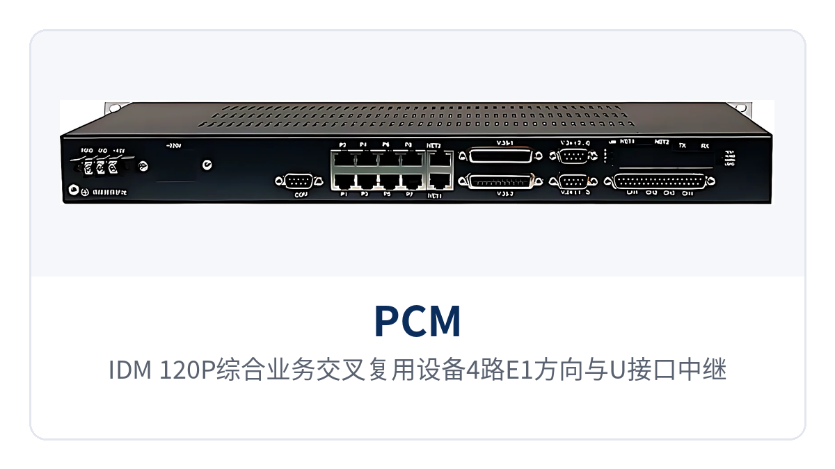
Figure 2: Networking topology of the 4xE1 directions and U interface trunk cards of the IDM-120P Integrated Service Cross-Connect Multiplexing Equipment
How do dual power supply and dual ringing current backup, alarms, and network management ensure continuous operation?
Continuous operation capability is supported by a three-layer design of power supply, ringing current, and alarms. The dual power supply and dual ringing current modules are online simultaneously, each carrying half the load, and the power supplies remain in half-power mode for long periods, reducing temperature rise and losses and extending module life accordingly. For private network equipment that runs online for long periods, this design turns power supply modules from wear parts into components whose replacement can be scheduled.
When a single power supply or ringing current module fails, the other module continues to supply power and ringing current, and the services of the unit are unaffected. For locations such as substations and unattended sites where an immediate site visit is inconvenient, this layer of redundancy downgrades a module failure from a service outage to a maintenance event that can be handled on a planned basis.
Alarms have three outputs: the device emits an audible alarm when the E1 state changes; panel indicator LEDs show the specific alarm state, so on-site personnel can judge without logging in to the network management system; and rack alarm information can be led to the equipment room's main alarm. On the network management side, configuration, query, and fault statistics are performed through the RS232 or RS485 interface, and with RS485, multiple devices can be cascaded for unified viewing.
Differentiated value: 4xE1, 128-time-slot cross-connection, dual power supply backup
| Value | Corresponding Capability | Value to the Customer |
|---|---|---|
| 4 E1 channels + 128 time-slot cross-connection | 4 E1 directions for receive/transmit, two-stage scheduling of the 128 time-slot cross-connect matrix | A single unit performs multi-direction private network time slot scheduling, with local transfer of cross-E1 services, so no separate cross-connect equipment is needed for each direction |
| Dual power supply backup | Dual power supplies and dual ringing current modules operating in half-power mode; the unit keeps working when one module fails | In continuous-operation scenarios, a power supply or ringing current module failure does not interrupt online services, and maintenance can be scheduled in a planned window |
| 5-7 km twisted pair | The U-interface trunk card carries V.35, 10BASE-T, V.24, X.21 and 64K codirectional services over twisted pair using 2B1Q encoding | Remote stations access over existing twisted pair, eliminating optical fiber laying and civil works |
| More than 30 interface cards | 8 universal slots plus 2 expansion slots; more than 20 interface cards and more than 30 subscriber interfaces available | Voice, data and Ethernet services are configured card by card according to the service list, and site service adjustment does not require replacing the unit |
Typical Application Scenarios
The IDM-120P 128 time-slot cross-connect PCM multiplexer is intended for private network scenarios that use E1 as the transmission medium and need to aggregate voice and data access and allocate them across directions. The 4 E1 directions can form chain, star and tree networks with other PCM multiplexers, and the networking topology is adjusted according to site distribution. As an integrated service access device, it completes voice, data, video surveillance and dedicated line access within one chassis. In the government private network optical fiber communication solution of Raytrans, such time-slot cross-connect equipment is often used together with optical multiplexing equipment to provide narrowband and broadband integrated service access capability.
Electric Power Private Network: Simultaneous Transmission of Voice Channels and Telecontrol Data Between Substations and Dispatch Centers
Between substations, switching stations and dispatch centers of an electric power private network, both dispatch telephone and telecontrol and monitoring data need to be transmitted. The device aggregates the E1 channels of all directions, allocates voice channels and data to the corresponding channels at the 64K time slot level, and one E1 carries both types of services at the same time. When a new bay is added or service assignment is adjusted, only the cross-connect configuration is changed, and the external cabling remains unchanged.
Substation equipment rooms are generally laid out with 19-inch standard cabinets; the 1U chassis occupies little space and can be installed in the same cabinet as existing transmission equipment. The dual power supply and dual ringing current backup operate in half-power mode, so dispatch telephone remains available when a single module fails; when the E1 status changes, the device issues an audible alarm, and on-duty personnel can find link anomalies without checking the network management system unit by unit.
Public Security Private Network: Telephone and Surveillance Backhaul Between Police Stations and Command Centers
The dedicated lines between police stations, traffic police squadrons and command centers mainly carry telephone, inside line contact and video surveillance backhaul. The device mixes FXO/FXS voice channels, V.24 data and 10BASE-T Ethernet cards in the same chassis, multiplexes multiple types of services onto the E1 channel to the command center, and does not require a separate transmission device for each type of service.
When surveillance sites are scattered, the U-interface trunk card can send remote images and control data into the E1 channel over twisted pair, so the front end does not need new optical cables. When front-end sites increase, interfaces are expanded by inserting cards, the wiring and cabinet layout in the equipment room remain unchanged, and capacity expansion does not affect online services.
Financial Branches: Voice and Service Data Access on Savings Office Dedicated Lines
The dedicated lines between savings offices, sub-branches and the branch data center carry savings service data, internal telephone and self-service equipment surveillance. The device configures V.24/V.35 data ports together with FXS and FXO voice channels in the same chassis, services are allocated to E1 directions by time slot, and the branch side needs only one set of equipment and one pair of E1 channels.
Unattended branches place more emphasis on power supply and alarms: dual power supply backup means a single module failure does not affect business, rack alarms can be connected to the branch's power and environment monitoring, and E1 link anomalies are viewed centrally on the branch network management side. When a branch relocates or services are adjusted, only cards and time slots are reconfigured, and the unit itself continues in use.
How to Select a PCM Multiplexer
Selection starts with service inventory. Once the five items are checked one by one, the configuration is basically determined, avoiding additional cards after ordering. Fill in the following five items according to actual on-site statistics; for items without data yet, reserve margin according to the existing service list, and then check the card combination with the manufacturer.
- Take stock of service capacity: number of voice channels, number of 64K codirectional and V.24 data channels, and bandwidth required for V.35; the total must not exceed the configuration limit of 16 channels of 64K and 8 channels of n×64K.
- Determine the number of E1 directions: count how many transmission directions are needed and whether cross-direction transfer is required; when cross-direction scheduling is frequent, the 128 time-slot cross-connection needs to be completed within one device.
- Check against the interface list: which interfaces are needed for voice, data and Ethernet, match them item by item among the more than 20 interface cards, and leave expansion slots for optical interfaces or future services.
- Assess line conditions: where optical fiber is available, plug in PDH optical interface modules to obtain 4 optical directions and 4 100M Ethernet ports; where only twisted pair is available, choose the U-interface trunk card, covering 5 to 7 km.
- Confirm clock and signaling: when interfacing with an exchange, specify the connection on the exchange interface side, and confirm both the central office and remote end usages at the time of ordering.