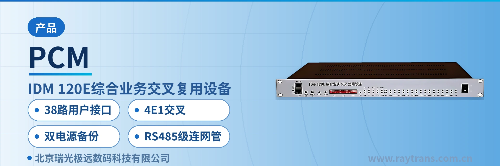
IDM-120E Integrated Service Cross-Connect Multiplexing Equipment
38 service channels shared across 4 E1 links, two-stage 128 time slot cross-connect, no additional equipment for card replacement or capacity expansion
The IDM-120E Integrated Service Cross-Connect Multiplexing Equipment uses a standard 19-inch 1U chassis and is a PCM multiplexer that handles up to 4 E1 signals; it provides 15 universal slots and 4 expansion slots, supports 30 channels of 64K plus 8 channels of n×64K subscriber interfaces, and can be configured with more than 20 types of interface cards as required.
The IDM-120E Integrated Service Access Device is a 38-channel subscriber interface 4E1 cross-connect PCM multiplexer developed by Beijing Ruiguang Jiyuan Digital Technology Co., Ltd. It multiplexes narrowband services such as voice, data, and video surveillance onto E1 or optical fiber channels for transmission, and can also be used as optical multiplexing equipment. The unit uses a standard 19-inch 1U chassis, with 15 universal slots and 4 expansion slots, providing 30 channels of 64K plus 8 channels of n×64K subscriber interfaces, and more than 20 types of interface cards can be configured as required.
For private network sites that need to complete voice channel access, time slot scheduling, and dedicated line uplink within a single device, this time-slot cross-connect equipment consolidates these tasks into one 1U chassis, and the 38 channels of service can be transmitted separately in 4 E1 directions. Cabinet space and the amount of cabling within the site are reduced accordingly; new services only require replacing interface cards and adjusting the configuration, with no need to add another device, making product showcase and deployment simpler.
Key Specifications at a Glance: 4 E1 directions · 38 subscriber interfaces · 19 slots (15 universal + 4 expansion) · 128 time slot cross-connect matrix · dual power supply and dual ringing current · RS232/RS485 network management
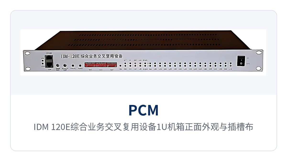
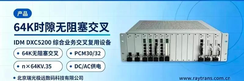
Figure 1: Front appearance and slot layout of the 1U chassis of the IDM-120E Integrated Service Cross-Connect Multiplexing Equipment
What kind of device is the 38-channel subscriber interface 4E1 cross-connect PCM multiplexer?
The core of the 38-channel subscriber interface 4E1 cross-connect PCM multiplexer is a 128 time slot cross-connect matrix with two-stage time slot cross-connection, enabling data and signaling cross-connection from subscriber to subscriber, subscriber to line, and line to line. The device can therefore perform PCM multiplexing and also serve directly as 4E1 time-slot cross-connect equipment, with voice channels and data within the site allocated at the time slot level without changing external cabling.
In addition to E1 lines, the IDM-120E can also be fitted with PDH optical interface modules, providing 4 optical directions and 2 channels of 100M Ethernet, with broadband and narrowband services multiplexed uniformly over E1 or optical fiber. When the private network backbone uses optical fiber, a single device at the site can send telephone, data, and Ethernet services onto the optical path, forming a multi-service integrated platform that combines PCM multiplexing and Ethernet access, and is also suitable as an access node device in a government private network optical fiber communication solution.
How to configure more than 20 types of interface cards: slot and subscriber interface capacity
Slot configuration determines the margin for service expansion. The IDM-120E uses a 19-inch 1U chassis with 15 universal slots and 4 expansion slots; voice, data, and multi-timeslot service cards are mixed as required on site, and once configured the unit can carry 38 channels of subscriber interface services. When service types change, it is sufficient to replace the corresponding card and adjust the time slot configuration, while the chassis and the wiring sequence to the patch panel remain unchanged.
The IDM-120E adopts an independent subscriber module design, with voice, data, and audio interfaces configured independently by slot, one service type corresponding to one interface card. Optional data interface cards include 64K codirectional, V.24/V.28 (RS232/RS485), V.35 (n×64K), and 10Base-T, and optional voice channel interface cards include polarity reversal and caller ID telephone (FXO, FXS), magneto, and hotline.
Audio and trunk services have another group of optional interfaces: 2100 Hz carrier magneto, carrier, EM 2/4-wire audio, high-fidelity audio, baseband trunk interface card, Signaling System No. 1 card, and telephone switching card, totaling more than 30 types of subscriber interfaces, with interface types freely changed according to the service. Voice and data on one E1 can be arranged in a mixed manner, so that voice channels and data of different disciplines within the site share one dedicated line.
Multi-timeslot services are carried by the built-in 4 multi-timeslot card channels, which can accept V.35 cards and 10Base-T cards with n×64K bandwidth, and can also provide high-speed asynchronous RS232 or RS485 interfaces. The V.35 card can operate in both DTE and DCE modes, supporting synchronous data services such as router interconnection; the 10Base-T card provides n×64K Ethernet access channels for packet services without occupying an entire E1, facilitating flexible bandwidth occupation for services such as video surveillance dedicated line access.
What functions does one device perform: function overview
The IDM-120E is a PCM multiplexer that consolidates multiplexing, cross-connection, access, network management, and power supply backup in the same chassis; the function items and their roles are listed in the table below. When checking functions, confirm row by row against the table, then decide the card combination according to the site service list, which avoids the situation of having cross-connect capability configured but lacking service interfaces.
Function | Description |
|---|---|
E1 multiplexing and cross-connection | Provides E1 line receive/transmit in 4 directions, with a built-in 128 time slot cross-connect matrix, completing data and signaling cross-connection from subscriber to subscriber, subscriber to line, and line to line |
Subscriber interface access | 15 universal slots plus 4 expansion slots, configurable with 30 channels of 64K plus 8 channels of n×64K subscriber interfaces, totaling 38 channels of subscriber interface services |
Multi-timeslot data channels | Built-in 4 multi-timeslot card channels, accepting n×64K V.35 cards and 10Base-T cards, and also providing high-speed asynchronous RS232 or RS485 interfaces |
Optical fiber and Ethernet expansion | PDH optical interface modules can be inserted, providing 4 optical directions and 2 channels of 100M Ethernet, with broadband and narrowband services multiplexed over E1 or optical fiber |
Clock synchronization | Supports master clock, external clock, line clock, and user clock, configurable as exchange interface or subscriber interface, compatible with both central office and remote end |
Network management and alarms | Network management interfaces are available in RS232 and RS485 forms; RS485 can cascade multiple devices simultaneously, with rack alarm output and audible E1 status alarms |
Power supply and ringing current backup | Dual power supply and dual ringing current modules are available; the power supply operates in half-power mode, and the unit still works normally when a single module fails |
Technical Specifications
The parameter table lists the IDM-120E specifications in eight categories: line, capacity, slots, interfaces, cross-connection, clock, network management, and power supply, among which the number of E1 directions, subscriber interface capacity, and cross-connect matrix are the three basic figures for configuration calculation. During site calculation, first determine the cards according to the number of service channels, then determine the line resources according to the number of E1 directions, and finally check whether the network management mode and power supply backup meet the equipment room conditions.
Item | Parameter/Specification | Description/Applicable Conditions |
|---|---|---|
E1 line directions | 4 directions | 38 channels of subscriber interface services can be allocated to the 4 E1 directions for transmission |
Subscriber interface capacity | 30 × 64K + 8 × n×64K | 38 channels of subscriber interface services in total |
Chassis and slots | 19-inch 1U, 15 universal slots + 4 expansion slots | Mixed insertion of voice, data and multi-time-slot service cards |
Interface cards and interface types | More than 20 types of interface cards, more than 30 types of subscriber interfaces | Including FXO/FXS, magneto, EM 2/4-wire audio, V.35, 10Base-T, etc. |
Cross-connect matrix | 128 time slots, two-stage time-slot cross-connection | Can be used standalone as a 4E1 time-slot cross-connect equipment |
Clock modes | Master clock, external clock, line clock, user clock | Can be set as exchange interface or subscriber interface, compatible with both central office and remote end |
Optical interface expansion | 4 optical directions, 2 × 100M Ethernet | Requires insertion of a PDH optical interface module |
Network management interface | RS232, RS485 | RS485 supports cascading of multiple devices simultaneously, with rack alarm output |
Power supply and backup | Dual power supply, dual ringing current modules | The unit still works normally when a single module fails |
Clock, Network Management and Alarms: How to Manage Unattended Sites
Clock synchronization determines the stability of inter-station telephone and data services. The IDM-120E can be set to multiple clock modes including master clock, external clock, line clock and user clock, and can be configured as an exchange interface or a subscriber interface, compatible with both central office and remote end, so the same model can be used at both the central station and remote stations. During networking, configure it to extract the clock on the trunk side and follow it at the terminal end, which reduces slips and call drops caused by two-stage clock slipping.
The reliability of unattended sites is underpinned by two capabilities: power supply and alarms. The IDM-120E adopts dual power supply backup and dual ringing current backup; the power supply operates in half-power mode to extend its service life, and the unit still works normally when a single module is damaged, so voice channel ringing current is not interrupted by the failure of one module. The main unit issues an audible alarm when the E1 state changes, the panel indicator LEDs show the specific alarm state, and rack alarm information is output at the same time.
Network management functions provide configuration, query and fault statistics management for the device. The network management interface is available in two forms, RS232 and RS485; with RS485, multiple devices can be cascaded simultaneously, with rack alarm output. Once one bus connects multiple devices in the equipment room, the duty room can monitor device status at any time through the network management system, without visiting each site to check the panel indication.
Networking Approaches: How to Build Chain, Star and Tree Networks
The IDM-120E provides E1 line receive/transmit in 4 transmission directions and can be used together with the IDM-240 series, IDM-120 series, IDM-30 series and IDM-mini series to form chain networks, star networks or tree networks according to capacity requirements and site distribution. The central station aggregates with a high-capacity chassis, and sites along the line select the 38-channel subscriber interface 4E1 cross-connect PCM multiplexer according to service volume, balancing line utilization and investment.
During networking, plan the E1 directions and time slots according to service flow: direct inter-station services each occupy one direction, services requiring transfer at the central station are time-slot transferred by the cross-connect matrix, and the same pair of E1s can carry voice and data simultaneously. When sites are added or service assignment is adjusted, simply modify the corresponding entries in the cross-connect configuration table, while the transmission lines and opposite-end devices remain unchanged.
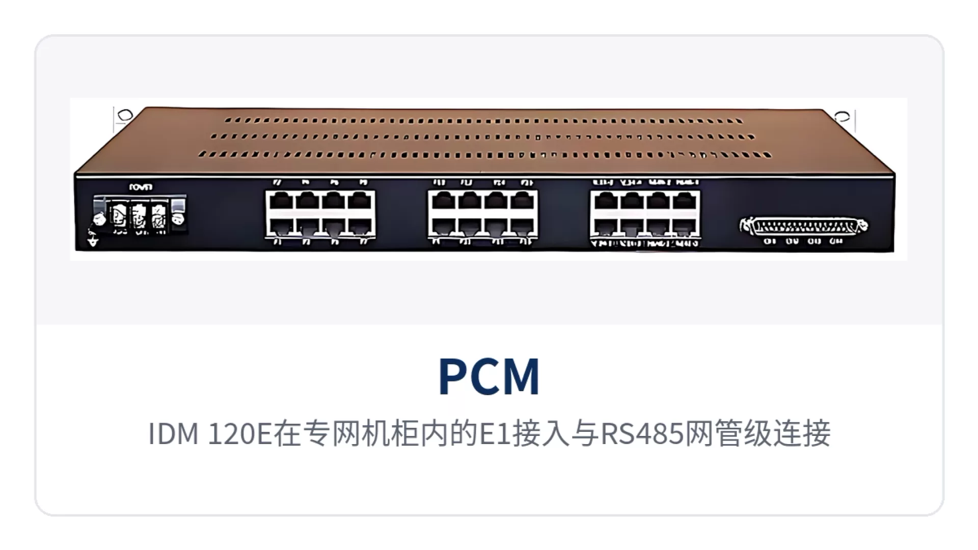
Figure 2: Schematic of E1 access and RS485 network management cascade wiring for the IDM-120E in a private network cabinet
Typical Application Scenarios
The 38-channel subscriber interface 4E1 cross-connect PCM multiplexer is mainly used at private network sites that rely on E1 or optical fiber for transmission and need to concentrate voice and low-speed data upstream. The grassroots nodes of the electric power, public security and financial industries have similar requirement patterns, differing mainly in service interface combinations and alarm management approaches. The service composition and configuration points are described below by industry.
Electric Power Private Network: Dispatch Telephone, Telecontrol Data and Video Surveillance on the Same Channel Upstream
Substations and power supply stations in the electric power private network usually carry three types of services at the same time: dispatch telephone, telecontrol and monitoring data, and video surveillance, with widely varying interface types and service volumes. As an integrated service access device, the IDM-120E uses FXO/FXS cards and magneto cards to access dispatch telephones, V.24/V.28 cards to carry telecontrol data, and 10Base-T cards to access video surveillance channels; the card combination is adjusted according to the actual services at the site, and the interface types in the product showcase can cover on-site requirements.
The 38 channels of services can be transmitted separately over the 4 E1 directions, or sent upstream over optical fiber through an optical multiplexing equipment by inserting a PDH optical module. A site needs only one 1U device and one set of wiring, reducing cabinet modification and wiring quantities; the clock for cross-station dispatch telephones is extracted on the line side and followed by terminal sites from the trunk clock, making call quality more stable.
Public Security Private Network: Station Telephone, Intranet Data and Checkpoint Video Backhaul
Services at grassroots stations and checkpoint sites of the public security private network are mainly telephone, intranet data and video backhaul; sites are distributed and mostly unattended equipment rooms. The IDM-120E provides internal voice channels for stations with FXS cards, accesses intranet data terminals with RS232/RS485 cards, and carries checkpoint video backhaul channels with 10Base-T cards; all services are multiplexed to the uplink E1 direction. Together with Raytrans' government private network optical fiber communication solution, it enables centralized bearing of video surveillance dedicated line access.
The O&M pressure of unattended equipment rooms centers on power supply and alarms. Dual power supply and dual ringing current module backup keep the unit working normally when a single module is damaged; when the E1 state changes, the main unit issues an audible alarm and outputs a rack alarm, and on-duty personnel check status uniformly across multiple devices cascaded via RS485, reducing on-site inspection frequency.
Financial Private Network: Voice, Surveillance and Office Data Access at Business Outlets
Business outlets of the financial private network need to backhaul counter voice, video surveillance and office data to the branch or data center; the lines are mostly leased E1 leased lines with a limited number of channels. The IDM-120E connects counter telephones to voice channel cards, carries surveillance and office data with 10Base-T cards and V.35 cards respectively, and allocates voice and data within the same E1 by 64K time slot; relying on the capability of the time-slot cross-connect equipment, one leased line runs three types of services simultaneously.
When an outlet is upgraded or expanded, replacing interface cards and adjusting time slot allocation adds services without reapplying for lines. The 1U chassis height suits installation in small outlet cabinets, the dual power supply modules can be connected to two power feeds respectively, and the unit still works normally when a single module fails, so counter call handling is not interrupted by the failure of one module.
How to Select and Deploy
Selection starts from the service list; five items checked one by one determine the configuration: number of service channels and interface types, number of E1 directions, whether optical ports and Ethernet expansion are needed, clock and network management modes, and power supply and ringing current backup requirements. First list clearly the number of voice channels, data and video channels at existing sites, then convert them into the number of plug-in cards and E1 resources, and the configuration table will not end up with enough slots but insufficient service time slots.
During deployment, secure the 1U chassis in the cabinet, connect the E1 lines and subscriber cables, then verify the clock source and frame structure first, and then verify voice channels and data channels one by one. In the alarm commissioning stage, confirm that the audible alarm, panel indicator LEDs and rack alarm output are consistent in the three places, bring the multiple devices cascaded via RS485 into the network one by one on the network management side, and verify the configuration query and fault statistics functions at the same time.