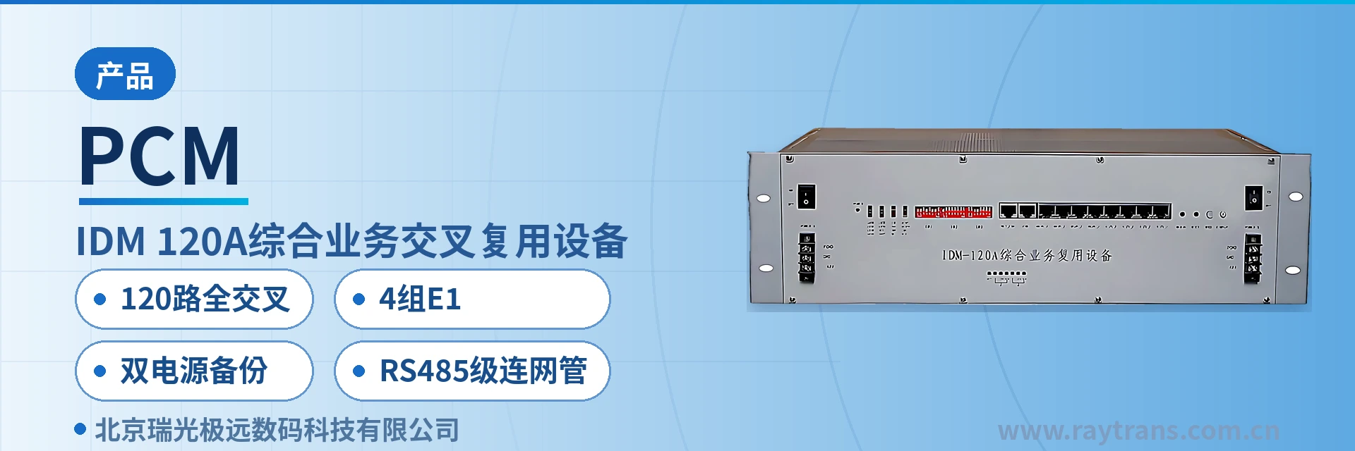
IDM-120A Integrated Service Cross-Connect Multiplexing Equipment
4E1 non-blocking full cross-connect, mixed insertion of over 20 service cards in one chassis, hot-swappable, card-by-card spare parts
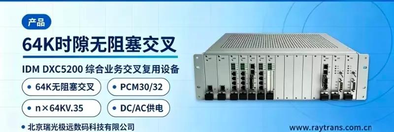
The IDM-120A Integrated Service Cross-Connect Multiplexing Equipment uses a 19-inch 3U standard chassis to implement non-blocking full cross-connect multiplexing of 120 channels of 64K services over 4 E1 links. Its pluggable card-based structure simplifies maintenance and management. A single 3U chassis can provide 120 subscriber interfaces and supports more than 20 optional service types. Its 4E1 cross-connect processing is currently the most highly integrated in the product line.
IDM-120A Integrated Service Cross-Connect Multiplexing Equipment is a 19-inch 3U chassis-based 120-channel 64K full cross-connect multiplexer developed by Beijing Ruiguang Jiyuan Digital Technology Co., Ltd. (Raytrans). It is used to allocate voice, data, and video surveillance services on 4 E1 directions to any line and subscriber channel non-blockingly by 64K time slot, and is an integrated service access device for multi-service scenarios.
Key Specifications at a Glance: 120-channel 64K full cross-connect · 4 E1 receive/transmit · 3U chassis with 15 user cards · over 20 types of pluggable service cards · dual power supply and dual ringing current backup · RS485 cascaded network management
What Is the IDM-120A 120-Channel 64K Full Cross-Connect Multiplexer?
The unit consists of 1 E1 central management unit (CMU) card, 15 user (USER) cards, and AC or DC power boards. The CMU card is mandatory, provides 4 E1 interfaces, and uniformly manages the E1 channels and all user cards. Service capacity increases card by card with the number of user cards. As a PCM multiplexer for private network access, the IDM-120A delivers the integrated voice, data, and video access capabilities covered in the product showcase within a 3U chassis.
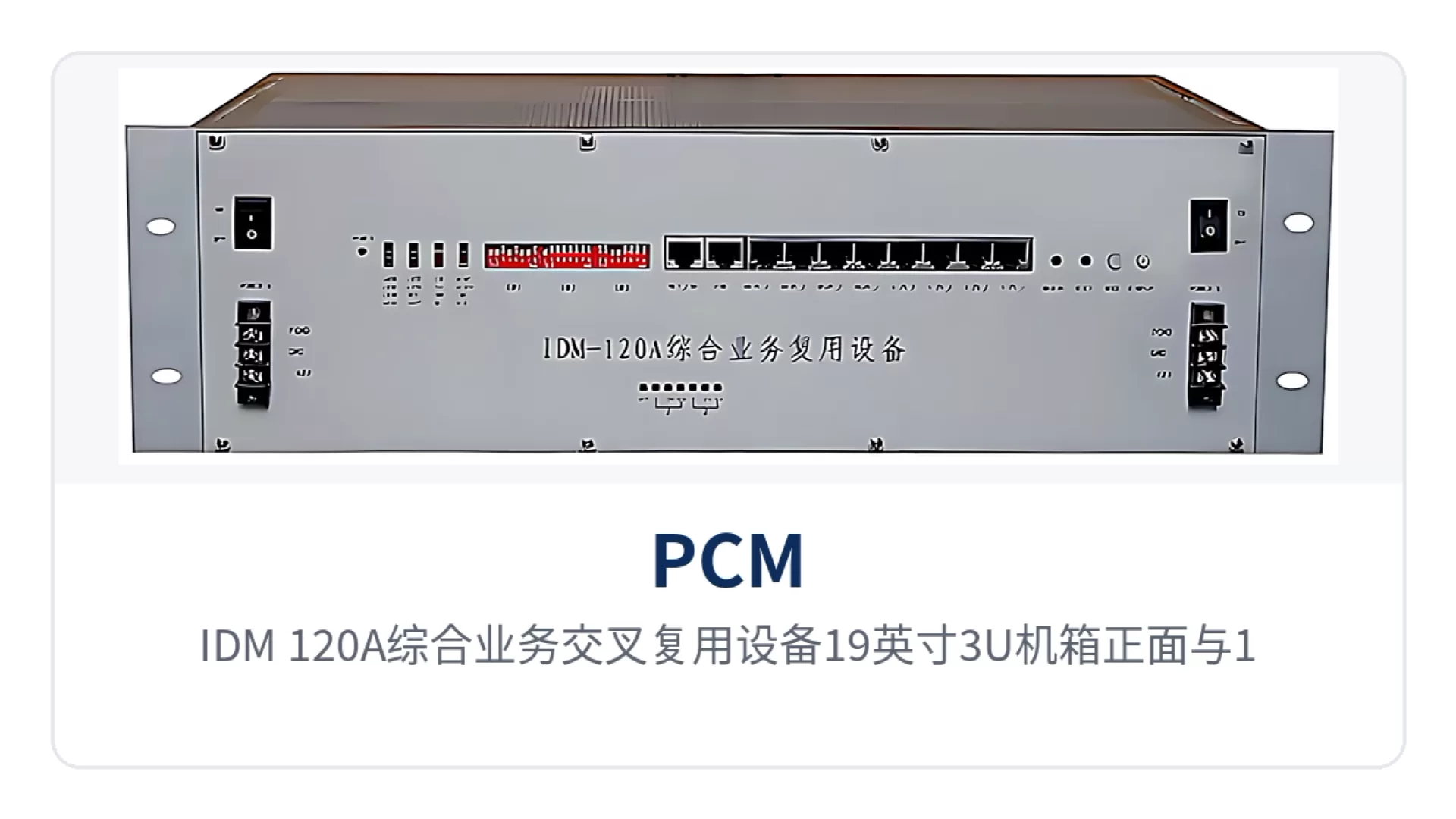
Figure 1: Front view of the IDM-120A Integrated Service Cross-Connect Multiplexing Equipment 19-inch 3U chassis and close-up of 15 user card slots
Each USER card provides 8 subscriber interfaces, and 15 cards in full configuration provide 120 channels. The transmit and receive gain of each voice channel can be adjusted directly outside the user card panel. The card-based structure supports hot-swappable operation, so capacity expansion, card replacement, and maintenance do not require powering down the entire unit.
Modular card configuration allows the same 3U chassis to be fully populated with telephone voice channels or with data and video interfaces, and a site can be configured according to its on-site service list. Spare parts are counted by card rather than by unit, which reduces the number of spare parts and maintenance costs in the equipment room. The same card type can be interchanged between sites, so during emergency repair a card can be removed from a nearby site and used as a replacement without waiting for shipment of a complete unit. Raytrans has maintained a unified card type and network management system across this series, ensuring spare parts commonality.
What the Equipment Can Do: Function Overview
As an integrated service access device, the IDM-120A combines E1 multiplexing, 64K full cross-connect, and multi-service access in a 3U chassis. The following table lists capabilities and functions by function item, so that capacity, interfaces, and redundancy configuration can be checked line by line against the site service list during selection. Each item in the table corresponds to the commercial card configuration list, so on-site confirmation no longer requires consulting the entire manual.
Function | Description |
|---|---|
120-channel full cross-connect | 120 channels of 64K services on 4 E1 groups are non-blockingly fully cross-connected, and any subscriber channel can be allocated to any time slot in any E1 direction |
4 E1 receive/transmit | Provides E1 line receive/transmit in 4 transmission directions and can be networked with the IDM-240 series, IDM-120 series, IDM-30 series, and IDM-mini series |
Card-based capacity expansion | 1 CMU card provides unified management; the chassis can hold 15 USER cards, each with 8 subscriber interfaces, providing 120 channels in full configuration |
Over 20 service interface types | Voice, data, and video service cards can be mixed, covering FXO, FXS, magneto, V.24, V.35, codirectional 64K, Ethernet, and video |
4 multi-timeslot card channels | Built-in 4 multi-timeslot card channels support n×64K bandwidth V.35 cards and 10Base-T cards, and can also provide high-speed asynchronous RS232 or RS485 |
Multiple clock modes | Can be set to master clock, external clock, line clock, or user clock, and can be set as exchange interface or subscriber interface, compatible with both central office and remote end |
Voice gain adjustment | The transmit and receive gain of each voice channel is adjustable outside the user card panel and can be set on site according to line attenuation |
Hot-swappable maintenance | USER cards support hot-swappable operation, so card replacement and capacity expansion do not require powering down the entire unit |
Network management configuration and query | Supports device configuration, status query, and fault statistics management; network management interfaces are available as RS232 and RS485 |
Monitoring and alarm | Audible alarm when E1 status changes, panel indicator LEDs showing alarm state, rack alarm output, and real-time network management monitoring |
Dual power supply and dual ringing current backup | Dual power supply and dual ringing current modules back up each other, so the equipment continues to operate normally when a single module fails; half-power mode extends power supply life |
How Is 120-Channel 64K Non-Blocking Cross-Connection on 4 E1 Groups Implemented?
Non-blocking full cross-connect means that any 64K time slot can be allocated to any output time slot, and newly added circuits do not occupy the cross-connect resources of services already in operation. Allocating 120 channels of services among 4 E1 groups is limited only by the number of line time slots, not by internal matrix blocking. This is the core value of the time-slot cross-connect equipment: cross-connection scheduling is completed inside the chassis, and no separate external cross-connect unit is required.
Knowledge block: E1 base group and PCM30/32 frame structure. An E1 line has a rate of 2.048Mbps and complies with ITU-T G.703. Each frame is divided into 32 time slots, where TS0 carries frame alignment and alarms, TS16 carries channel-associated signaling (CAS), and the remaining 30 time slots each carry 1 channel of 64K service. The 4 E1 groups together provide exactly 120 cross-connectable 64 kbit/s service time slots.
Cross-connection relationships are delivered as configurations through the network management system, specifying subscriber channels and target E1 time slots one by one according to service planning. When a site adds or removes voice channels or adjusts service assignment, only the configuration is changed, while external cabling and opposite-end equipment remain unchanged, reducing on-site work.
Cross-connection of 4 E1 groups and access of 120 channels of services are integrated into the same 3U chassis, so an access node no longer needs separate cross-connect equipment and multiplexing equipment in series. The CMU card handles both E1 interface receive/transmit and time-slot scheduling for all user cards, reducing the number of devices and supporting power supplies in the cabinet.
How to Configure Over 20 Service Cards: Mixed Voice, Data, and Video in One Chassis
Service cards are divided into voice, data, and video by signal type and can be mixed in the same chassis. Over 20 card types cover access requirements from telephone voice channels to n×64K synchronous data and video images. The specific configuration is subject to the technical documentation supplied with the equipment and the on-site service list.
Voice: FXO cards connect to exchange-side voice channels, FXS cards connect directly to telephones, and hotline phone cards, EM 2/4-wire audio cards, magneto cards, 2100Hz magneto cards, and high-fidelity audio cards are also available
Data: V.24/RS485 data cards, V.24 synchronous clock adaptive cards, codirectional 64K cards, 10Base-T Ethernet cards, and n×64K/V.35 data cards
Video: H.263 video cards and MPEG4 video cards for private network image surveillance service access, capable of image backhaul in video surveillance dedicated line access scenarios
Multi-timeslot cards: built-in 4 multi-timeslot card channels support n×64K bandwidth V.35 cards and 10Base-T cards, and can also provide high-speed asynchronous RS232 or RS485 interfaces
V.35 operating mode: V.35 cards can operate in DTE or DCE mode, so no additional converter is required when the opposite-end device type differs
Unified network management: unified network management for the entire network, with serial port and Ethernet network management interfaces, allowing centralized viewing of each site's configuration and operating status
As a PCM multiplexer, the IDM-120A compresses voice into 64K voice channels using A-law encoding per ITU-T G.711 and places them into E1 time slots, while data and video services occupy the corresponding bandwidth by card type. Card configuration is usually completed in three steps: first count the site's telephone, audio, data, and video channels to determine the number of each card type; then check the time slot occupation of the 4 E1 groups and allocate services by direction; finally use the network management system to verify that the configuration matches the services actually enabled. In government private network optical fiber communication solutions, this card configuration approach can be implemented site by site according to the service list of each government department site.
How Dual Power Supply Backup and RS485 Cascaded Network Management Support Unattended Sites
Dual power supply and dual ringing current backup means that two power supply modules and two ringing current modules are configured in the chassis to back up each other, with the power supply operating in half-power mode. When a single module fails, the other continues to supply power and ringing current, and the equipment continues to operate normally; the reduced load also extends the service life of the power supply modules.
Monitoring and alarm are implemented at three levels: when E1 status changes, the main unit emits an audible alarm; panel indicator LEDs show the specific alarm state; and rack alarm output can be connected to equipment room environment monitoring. The network management system can check each site's device status and fault statistics at any time, so on-duty personnel do not need to inspect each unit in the equipment room.
RS485 cascaded network management connects multiple devices over a single bus, so a single terminal in the central equipment room can poll each site's configuration and alarms. The equipment also provides an RS232 interface for local standalone connection, and Ethernet can also be selected for network management, depending on site scale and existing equipment room conditions. In government private network optical fiber communication solutions, the Raytrans network management system can share the same monitoring channel with video surveillance dedicated line access services, further reducing the O&M burden of unattended sites.
Technical Specifications
The parameters in the table below are taken from the public product documentation of the IDM-120A Integrated Service Cross-Connect Multiplexing Equipment. The E1 interface complies with ITU-T G.703. The specific card configuration and redundancy configuration are subject to the manufacturer's technical documentation and commercial confirmation. For interface specifications not listed in the table, verify them item by item against the documentation supplied with the configured service cards. As a mature integrated service access device, this equipment offers strong product showcase value in PCM multiplexing and cross-connection scenarios.
Item | Parameter/Specification | Description/Applicable Conditions |
|---|---|---|
Chassis structure | 19-inch 3U standard chassis | Card-based structure for easy rack mounting and maintenance |
Subscriber interface capacity | 120 channels of 64K | Full configuration of 15 USER boards, with 8 subscriber interfaces per board |
E1 interface | 4-channel E1 receive/transmit (4 transmission directions) | Provided by the CMU board; supports non-blocking full cross-connect of 120 channels of 64K across 4 groups of E1 |
E1 line rate | 2.048Mbps | E1 base group rate, compliant with ITU-T G.703 |
Card configuration | 1 CMU (mandatory) + 15 USER boards + power board | The CMU centrally manages the E1 interfaces and all user cards |
Service type | Voice, data, video | More than 20 types of service cards can be mixed as required |
Multi-time-slot channel | 4 built-in channels | Can be fitted with n×64K bandwidth V.35 cards and 10Base-T cards, or provide high-speed asynchronous RS232/RS485 |
Clock mode | Master clock/external clock/line clock/user clock | Can be set as exchange interface or subscriber interface, compatible with both central office and remote end |
Voice gain | Transmit/receive gain adjustable outside the front panel | Each voice channel is set independently |
Hot-swappable | Supported on USER boards | Card replacement and capacity expansion require no power-down of the complete unit |
Network management interface | RS232/RS485, with Ethernet optional | With RS485, multiple devices can be cascaded at the same time, with rack alarm output |
Power supply mode | AC power board or DC power board | Optional dual power supply (DC and AC) |
Redundancy configuration | Dual power supply backup, dual ringing current backup | The equipment continues to operate normally when a single module fails |
Networking capability | 4 E1 transmission directions | Can be combined with the IDM-240 series, IDM-120 series, IDM-30 series, and IDM-mini series |
Typical Application Scenarios
As a time-slot cross-connect equipment for private network access nodes using E1 as the transmission medium, IDM-120A serves three typical scenarios: electric power, public security, and finance. Services are concentrated on dispatch telephone, telecontrol data, private network data, and video surveillance backhaul, and the 4 E1 directions can form point-to-point, chain, or star structures according to site distribution. Raytrans has accumulated extensive networking experience with this product series and can provide reference solutions for various private network users.
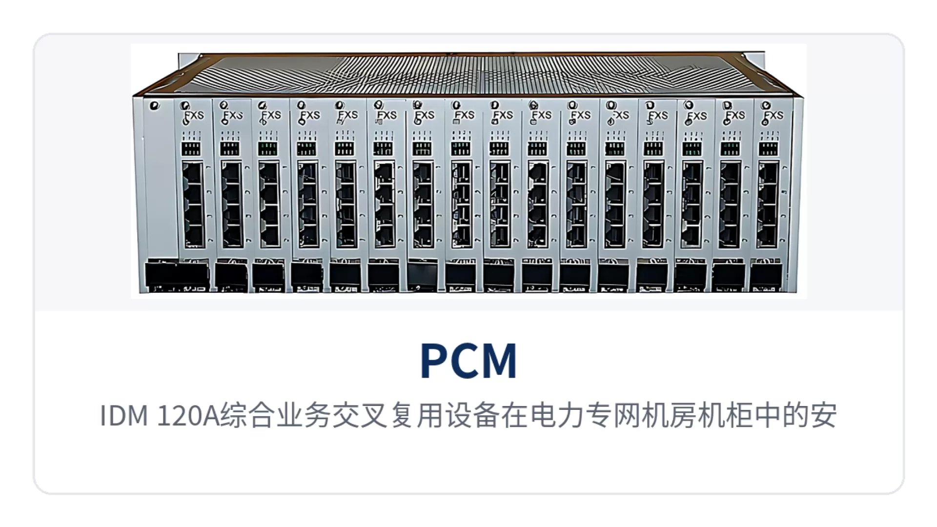
Figure 2: Installation of the IDM-120A Integrated Service Cross-Connect Multiplexing Equipment in an equipment room cabinet of an electric power private network, with E1 networking wiring diagram
Electric Power Private Network: Simultaneous Voice and Data Transmission Between Substations and the Dispatch Center
In electric power private networks, dispatch telephone and low-speed telecontrol and surveillance data run simultaneously between substations, switching stations, and the dispatch center. IDM-120A aggregates the E1 links from all directions and cross-connects voice channels and data to the target channels at 64K time slot granularity, so a single E1 can carry voice and data at the same time, reducing the number of private network lines. This PCM cross-connect capability also applies to government private network optical fiber communication solutions, where the device can serve as an access layer node for multi-service aggregation.
Substations are mostly unattended, and the interval between personnel visits is long. Dual power supply and dual ringing current backup keep services running when a single module fails, and panel alarms directly indicate the location of the faulty card, so O&M personnel can restore redundancy by card-by-card replacement on site without returning the complete unit to the factory. Spare parts only need to cover three categories: power supply modules, ringing current modules, and user cards, so equipment rooms do not need to stock a complete unit for every site.
Public Security Private Network: Voice and Video Surveillance Aggregation at Branch Bureaus and Police Stations
In public security private networks, voice dispatching and video surveillance backhaul dominate between branch bureaus, police stations, and the command center. With H.263 or MPEG4 video cards and FXS and FXO voice channel cards inserted in the chassis, a single device can connect both service types onto 4 groups of E1 for upstream transmission, providing a stable transmission channel for video surveillance dedicated line access.
When the number of police stations increases, capacity can be expanded by adding user cards and service cards according to service volume. On the command center side, RS485 cascaded network management polls the status of each site, and cross-site voice channel adjustments are completed by configuration without on-site re-cabling. Expansion is mainly by adding cards, while the chassis, power supply, existing cabling, and grounding remain unchanged.
Financial Private Network: Business Outlet Dedicated Line Access and Rack Alarm Linkage
In financial private networks, dedicated lines between business outlets and branch data centers carry service data and internal telephone. IDM-120A uses V.24/RS485 data cards and n×64K V.35 data cards to connect service data, and FXO and FXS cards to connect internal voice channels, with both service types multiplexed for upstream transmission in the same 3U chassis.
Outlet equipment rooms are usually unattended, and the rack alarm output can be connected to the power and environment monitoring system of the equipment room. Changes in E1 link status trigger both audible alarms and panel indications, and the network management side can query fault statistics remotely, significantly shortening fault location and attendance on site.