IDM OMP3500, Multiservice Access Platform, 2.5G Fiber Integrated Access Device, PCM Voice Data Image Multiplexing Platform, Physically Isolated Gigabit Ethernet Optical Transmission
Multiservice access platform, applied in the field of multiservice access platforms, communication/transmission/dispatch equipment for industry customers (to be refined in detail based on documentation)
The IDM OMP3500 2.5G Multiservice Access Platform is a multiservice access device launched by Beijing Ruiguang Jiyuan Digital Technology Co., Ltd. This 2.5G fiber integrated access device simultaneously transmits 16 groups of transparent E1, 2 groups of physically isolated wire-speed Gigabit Ethernet, 4 groups of physically isolated wire-speed 100M Ethernet and 30 channels of narrowband PCM services over 2.5Gbps fiber, and provides 2 groups of 2.5G fiber mutual backup. The IDM OMP3500 integrates telephone, leased-line data and Ethernet access into a single 19-inch standard chassis, replacing multiple stacked single-service optical terminals with one unit, suitable for access points in power, transportation, mining, public security, campus private networks and other scenarios requiring simultaneous voice and broadband services.
The PCM narrowband services of the IDM OMP3500 support voice, data, image and other user interfaces, and service cards can be replaced on-site according to site type; the platform has built-in non-blocking timeslot cross-connection between 2 groups of E1 and all user interfaces, and supports multiple clock modes to meet clock requirements of different application environments. In terms of power supply design, the IDM OMP3500 can simultaneously provide ~220V AC and -48V DC power, and can operate by connecting to the existing power supply system of the equipment room or unattended site.

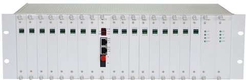
Figure 1: IDM OMP3500 Multiservice Access Platform overall diagram (19-inch chassis with service slots)
One Device, Multiple Services: IDM OMP3500 Core Functions Overview
The functions of the IDM OMP3500 revolve around 2.5G fiber transmission, TDM services, Ethernet services, protection and NMS. The core functions are as follows:
| Function | Description |
|---|---|
| 2.5G Fiber Transmission | Provides 2 SFP 2.5G optical transmission interfaces, single-mode (multi-mode optional), transmission distance 20km/40km/80km optional, supports point-to-point, chain, ring or 1+1 protection networks |
| 16 Groups E1 Transparent Transmission | Provides 16 groups of transparent E1, physical interface CC3-16 or CC3-8, compliant with ITU-T G.703, line code HDB3, interface impedance 75Ω/120Ω |
| Physically Isolated Wire-speed Gigabit Ethernet | Provides 2 groups of physically isolated wire-speed Gigabit Ethernet, data-plane isolated from 100M port groups, no bandwidth preemption between groups |
| Wire-speed 100M Ethernet | Provides 4 groups of physically isolated wire-speed 100M Ethernet, supports 10M/100M/1000M auto-negotiation |
| 30 Channels Narrowband PCM | Provides 30 channels of narrowband PCM service access, supports FXS/FXO, magneto, EM, RS232/RS422/RS485, GSM/CDMA and USER universal interface cards |
| Non-blocking Timeslot Cross-connection | Non-blocking timeslot cross-connection between 2 groups of E1 and all user interfaces, supports multiple clock modes |
| Dual Optical Port Mutual Backup | 2 groups of 2.5G fiber mutual backup; can be configured for mutual backup between fiber and PCM services on one group of E1 |
| SNMP NMS | Supports SNMP Ethernet NMS, can be integrated into the multiservice access device NMS system for unified management |
| Modular Expansion | 19-inch standard chassis, 3 service slots, hot-swappable cards, supports video surveillance and video conference cards |
| Dual Power Supply | Supports DC-48V, AC220V dual power supply, total power consumption ≤40W |
Knowledge Block: Working Principle of the 2.5G Multiservice Access Platform
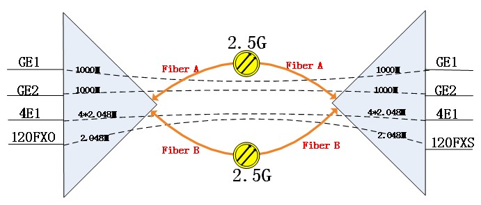
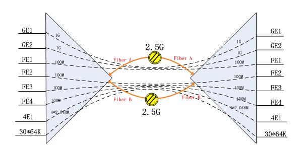
The 2.5G Multiservice Access Platform is a multiplexing device that multiplexes E1, Ethernet and narrowband PCM services onto a 2.5Gbps fiber for transmission. Taking the IDM OMP3500 as an example, the 2.5G optical bandwidth simultaneously carries 2 groups of Gigabit Ethernet, 4 groups of 100M Ethernet, 16 groups of transparent E1 and 30×64K narrowband PCM services; the 16 groups of E1 are transmitted transparently as-is, and the narrowband PCM services are connected after non-blocking timeslot cross-connection between 2 groups of E1 and all user interfaces. The IDM OMP3500 provides 2 groups of 2.5G optical ports (Fiber A/Fiber B) as mutual backup; when one fiber fails, services switch to the other, supporting point-to-point, chain, ring or 1+1 protection networks.
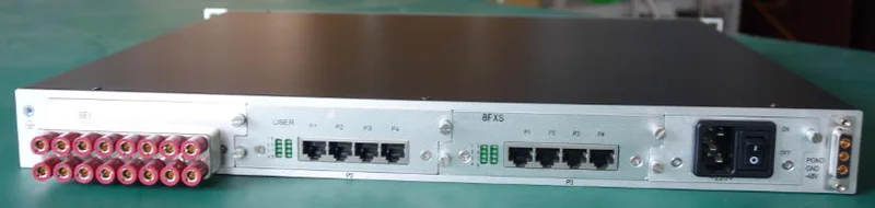
Figure 2: Device fiber multiplexing principle block diagram (dual 2.5G optical ports with E1, GE, FE, PCM service multiplexing and NMS channel)
Knowledge Block: Physically Isolated Wire-speed Ethernet
Physically isolated wire-speed Ethernet means that each Ethernet port group is completely isolated at the data plane and does not share bandwidth with others; each port forwards independently at the interface line rate (100M or 1000M). The IDM OMP3500 provides 2 groups of Gigabit and 4 groups of 100M, totaling 6 groups of physically isolated Ethernet. Port groups do not preempt bandwidth from each other and can simultaneously carry multiple independent networks such as office network, video surveillance network and production network; Ethernet standard protocol supports IEEE 802.3, with full/half duplex auto-negotiation.

Figure 3: IDM OMP3500 Ethernet and E1 interface panel close-up (GE/FE and CC3 series interfaces)
PCM Narrowband Services and Pluggable Interface Cards
PCM narrowband services are the part of the IDM OMP3500 for telephone and low-speed data access, providing voice, data, image and other user interfaces. Interface cards are configured by capacity per card, as detailed in the table below:
| Interface Card Type | Capacity per Card | Applicable Services |
|---|---|---|
| FXS/FXO Card | 10 or 8 channels per card | Analog telephone subscriber line/trunk line access |
| Magneto Card | 10 or 8 channels per card | Magneto telephone, commonly used in mining and emergency communication |
| 2/4-wire EM Interface Card | 4 channels per card | Switch E&M trunk |
| RS232/RS422/RS485 Card | 8 channels per card | Serial data services |
| GSM/CDMA Card | 2 channels per card | Wireless trunk or emergency channel |
| USER Universal Interface Card | Can mix 4 PCM service modules, up to 2 channels per module | General narrowband services combined on demand |
Figure 4: FXS/FXO telephone interface card display (10/8 channels narrowband PCM services per card)
Chassis Structure and Card Expansion
The IDM OMP3500 adopts a 19-inch standard chassis with modular design, providing 3 service slots in the chassis. Service cards support hot-swap, so capacity expansion or card replacement does not interrupt overall device operation; the device uses large-scale ASIC chip design with high integration, and the overall size and power consumption control make it more suitable for direct installation in existing communication equipment rooms. The service slots can mix FXS/FXO, magneto, 2/4-wire EM, RS232/RS422/RS485, GSM/CDMA, USER universal interface cards as well as video surveillance and video conference cards. When site service types change, smooth adjustment can be achieved by replacing cards.

Figure 5: 19-inch chassis with 3 service slots and hot-swappable service card installation diagram
Core Features and Design Highlights
The product features of the IDM OMP3500 are compiled from product documentation as shown in the table below. Specific selection should be confirmed with the manufacturer based on project requirements:
| Feature | Description |
|---|---|
| Multi-service Integration in One Device | 30 channels of narrowband PCM, 16 groups of transparent E1 and 6 groups of physically isolated Ethernet transmitted on the same 2.5G platform, reducing device stacking and equipment room space occupation |
| Dual 2.5G Optical Port Mutual Backup | 2 groups of 2.5G fiber mutual backup, and can be configured for mutual backup between fiber and PCM services on one group of E1, forming dual protection |
| Non-blocking Timeslot Cross-connection and Multiple Clocks | Non-blocking cross-connection between 2 groups of E1 and all user interfaces, multiple clock modes adapt to complex networking clock environments |
| Card-level Hot-swap Expansion | 3 service slots support hot-swap, can accommodate FXS/FXO, magneto, EM, RS232/RS422/RS485, GSM/CDMA, USER universal interface cards and video cards |
| Industrial Environment Suitability | Operating temperature -20℃~+50℃, dual power supply DC-48V/AC220V, total power consumption ≤40W, suitable for unattended equipment rooms |
No differentiated selling point information is currently available in the database; it is recommended to confirm with the manufacturer based on specific project requirements.
IDM OMP3500 Technical Specifications
The technical specifications of the IDM OMP3500 are as follows. Parameters are subject to product documentation, and specific configurations are subject to commercial confirmation; the overall appearance and structure are shown in the figure below.
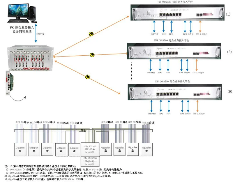
Figure 6: IDM OMP3500 product main image (19-inch standard chassis and panel appearance, for official website detail display)
| Item | Parameter/Specification | Description/Applicable Conditions |
|---|---|---|
| Optical Interface Type | SFP | Provides 2 SFP 2.5G optical ports, dual-fiber mutual backup |
| Fiber Mode | Single-mode (multi-mode optional) | Selected according to line distance |
| Optical Rate | 2.5Gbps | Wavelength 1310/1490/1550nm |
| Transmit Power | -1~-10dB | Single-mode typical value, subject to actual optical power meter measurement |
| Receiver Sensitivity | Better than -24dBm | Link budget needs to be verified for long-distance applications |
| Transmission Distance | 20km / 40km / 80km | Corresponds to the selected SFP optical module |
| E1 Bit Rate | 2.048Mbps | Line code HDB3, compliant with ITU-T G.703 |
| E1 Interface Impedance | 75Ω/120Ω | Frame structure PCM30/31, transparent mode |
| E1 Physical Interface | CC3-16 / CC3-8 | Corresponds to 16 or 8 groups of E1 output |
Ethernet and narrowband service interface parameters are as follows:
| Item | Parameter/Specification | Description/Applicable Conditions |
|---|---|---|
| Ethernet Transmission Rate | 10M/100M/1000M | Supports IEEE 802.3, full/half duplex auto-negotiation |
| Ethernet Groups | 2 groups Gigabit + 4 groups 100M | Physically isolated between groups, wire-speed forwarding |
| FXO/FXS Audio Range | 300Hz~3400Hz | Compression ITU G.711 A-law |
| FXO/FXS Impedance | Three-element complex impedance 200Ω+560Ω//0.1μF | Loop current 25mA/channel |
| EM 2/4-wire Audio Range | 300Hz~3400Hz | Balanced impedance 600Ω, return loss not less than 18dB |
| V.24 Interface | Async ≤9600bps; sync 64Kbps | Compliant with CCITT V.28 protocol |
| V.35 Interface | n×64Kbps (n=0~31) | Interface type RJ-45, compliant with ITU-T V.35, terminal interface compliant with ISO2593 |
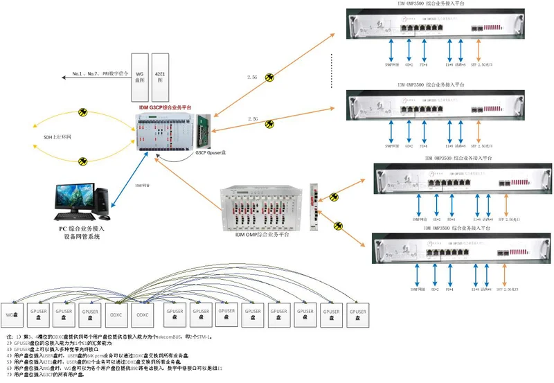
Figure 7: IDM OMP3500 data interface access diagram (V.24/V.35 and E1 services)
Power supply and operating environment parameters are as follows:
| Item | Parameter/Specification | Description/Applicable Conditions |
|---|---|---|
| Power Supply | DC-48V / AC220V | Dual power supply, can simultaneously provide ~220V and -48V |
| Total Power Consumption | ≤40W | Typical value |
| Operating Temperature | -20℃ ~ +50℃ | Relative humidity 0~95% (non-condensing) |
| Chassis Structure | 19-inch standard chassis | Modular, 3 service slots, hot-swap |

Figure 8: IDM OMP3500 dual power supply and equipment room deployment scenario (DC-48V/AC220V)
Typical Application Scenarios and Networking Modes
The IDM OMP3500 supports
FAQ
What services can the IDM OMP3500 transmit simultaneously?
The IDM OMP3500 (hyphenated form IDM-OMP3500 is the same model) 2.5G Multiservice Access Platform simultaneously transmits 16 groups of transparent E1, 2 groups of physically isolated wire-speed Gigabit Ethernet, 4 groups of physically isolated wire-speed 100M Ethernet and 30 channels of narrowband PCM services over 2.5Gbps fiber, and provides 2 groups of 2.5G fiber mutual backup; transmission distance 20km/40km/80km optional, corresponding to the selected SFP optical module, supporting point-to-point, chain, ring or 1+1 protection networks.
How to select the narrowband service interface cards for the IDM OMP3500?
The narrowband PCM services of the IDM OMP3500 support voice, data, image and other user interfaces, and service cards can be replaced on-site according to site type. Interface cards are configured by capacity per card: FXS/FXO card 10 or 8 channels per card, magneto card 10 or 8 channels per card, 2/4-wire EM interface card 4 channels per card, RS232/RS422/RS485 card 8 channels per card, GSM/CDMA card 2 channels per card, USER universal interface card can mix 4 PCM service modules (up to 2 channels per module). The above cards can be hot-swapped in the 3 service slots. Specific selection should be confirmed with the manufacturer based on project requirements.
Will services be interrupted when the fiber of the IDM OMP3500 fails?
The IDM OMP3500 provides 2 groups of 2.5G fiber mutual backup; when one fiber fails, services switch to the other optical port; it can also be configured for mutual backup between fiber and PCM services on one group of E1, forming dual protection. The device provides 2 SFP 2.5G optical transmission interfaces, supporting point-to-point, chain, ring or 1+1 protection networks.
| Item | Parameter/Indicator | Description/Applicable Conditions |
|---|---|---|
| Ethernet Transmission Rate | 10M/100M/1000M | Supports IEEE 802.3, full/half-duplex auto-negotiation |
| Ethernet Groups | 2 groups Gigabit + 4 groups Fast Ethernet | Physical isolation between groups, wire-speed forwarding |
| FXO/FXS Audio Range | 300Hz~3400Hz | Compression per ITU G.711 A-law |
| FXO/FXS Impedance | Three-element complex impedance 200Ω+560Ω//0.1μF | Loop current 25mA/channel |
| EM 2/4-Wire Audio Range | 300Hz~3400Hz | Balanced impedance 600Ω, return loss ≥18dB |
| V.24 Interface | Async ≤9600bps; Sync 64Kbps | Compliant with CCITT V.28 protocol |
| V.35 Interface | n×64Kbps (n=0~31) | Connector type RJ-45, compliant with ITU-T V.35, terminal interface compliant with ISO2593 |
Figure 7: IDM OMP3500 Data Interface Access Diagram (V.24/V.35 and E1 Services)
Power supply and operating environment parameters are as follows:
| Item | Parameter/Indicator | Description/Applicable Conditions |
|---|---|---|
| Power Supply Mode | DC-48V / AC220V | Dual power supply, can provide ~220V and -48V simultaneously |
| Total Power Consumption | ≤40W | Typical value |
| Operating Temperature | -20℃ ~ +50℃ | Relative humidity 0~95% (non-condensing) |
| Chassis Structure | 19-inch standard chassis | Modular, 3 service slots, hot-swappable with power on |
Figure 8: IDM OMP3500 Dual Power Supply and Equipment Room Deployment Scenario (DC-48V/AC220V)
Typical Application Scenarios and Networking Topologies
IDM OMP3500 supports
FAQ
Which services can be transmitted simultaneously on the IDM OMP3500?
The IDM OMP3500 (hyphenated form IDM-OMP3500 refers to the same model) 2.5G integrated service access platform simultaneously transmits 16 groups of transparent E1, 2 groups of physically isolated wire-speed Gigabit Ethernet, 4 groups of physically isolated wire-speed 100M Ethernet, and 30 channels of narrowband PCM services over a 2.5Gbps optical fiber, with 2 groups of 2.5G optical fibers providing mutual backup; transmission distances of 20km/40km/80km are optional, corresponding to the selected SFP optical module, and point-to-point, chain, ring, or 1+1 protection networks can be formed.
How are narrowband service interface cards for the IDM OMP3500 selected?
The narrowband PCM services of the IDM OMP3500 support various user interfaces including voice, data, and image, and service cards can be replaced on-site according to site type. Interface cards are configured by capacity per card: FXS/FXO cards with 10 or 8 channels per card, magneto ring cards with 10 or 8 channels per card, 2/4-wire EM interface cards with 4 channels per card, RS232/RS422/RS485 cards with 8 channels per card, GSM/CDMA cards with 2 channels per card, and USER universal interface cards that can accommodate 4 PCM service modules (up to 2 channels per module). The above cards can be hot-swapped with power on across the 3 service slots; specific selection should be confirmed with the manufacturer based on project requirements.
Will services be interrupted on the IDM OMP3500 in the event of an optical fiber failure?
The IDM OMP3500 provides 2 groups of 2.5G optical fibers with mutual backup; when one fiber fails, services are switched to the other optical port. It can also be configured so that PCM services on the fiber and one group of E1 back up each other, forming dual protection. The equipment provides 2 SFP 2.5G optical transmission interfaces and can form point-to-point, chain, ring, or 1+1 protection networks.
FAQs
Top 10 Common Questions About Telephone Optical Terminals
Based on years of experience in the production and R&D of telephone optical terminals…
View answerHow to Troubleshoot Common Faults of Telephone Optical Terminal?
Device cannot be powered on Check whether the power cable is connected correctly.
View answerWhat is the difference between single-fiber and dual-fiber?
The biggest difference between single-fiber and dual-fiber optical terminals lies in the optical modules on their…
View answerWhat is an Optical Terminal?
Many people are unfamiliar with the optical terminal, but in essence, it is a dedicated device for optical-electrical…
View answer