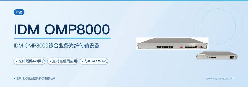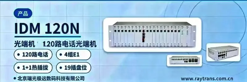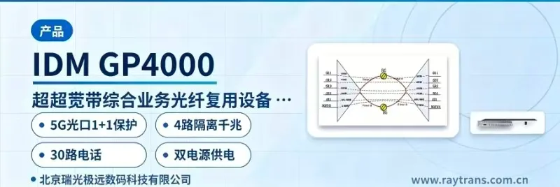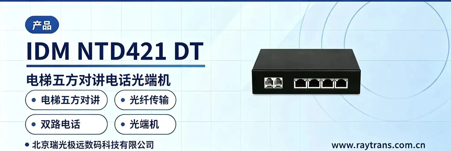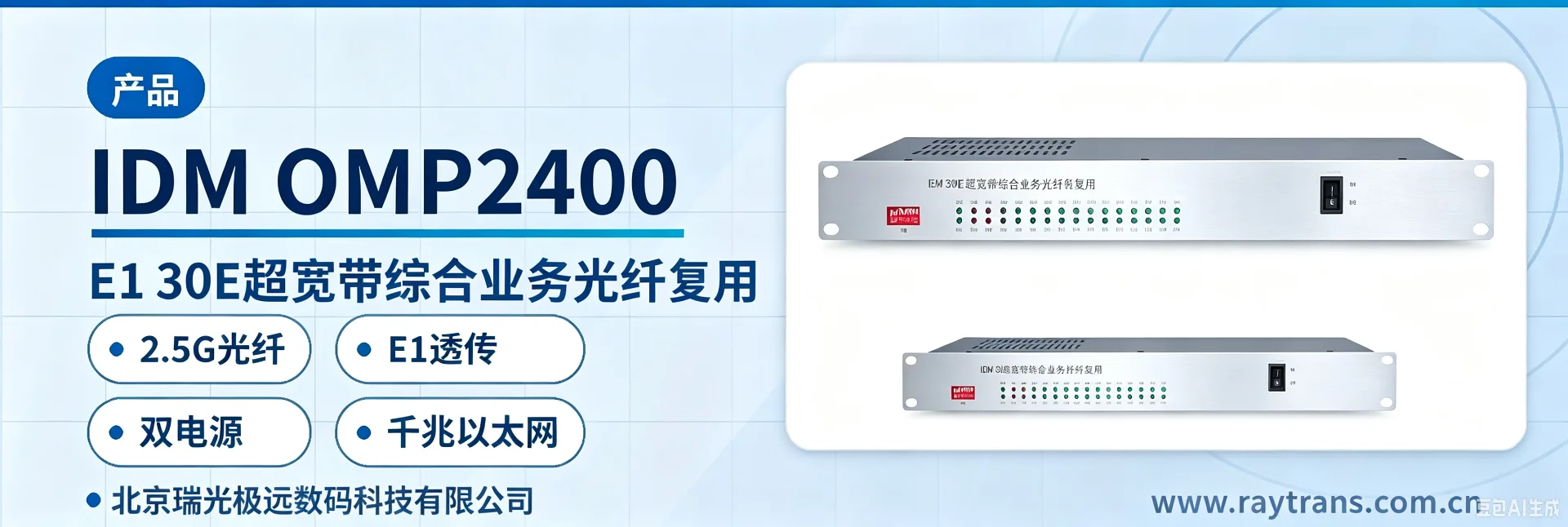
IDM OMP2400-4E1-30E Ultra-Broadband Integrated Service Optical Multiplexing Equipment
4-Channel E1 Plus 30-Channel Telephone and Gigabit Ethernet Transparent Transmission over One Fiber
Ultra-broadband integrated service optical multiplexing equipment that supports an SFP optical interface, a 2.5Gbps optical fiber rate, E1 interfaces, Ethernet interfaces and telephone audio interfaces, suitable for integrated service access and transmission.
The IDM OMP2400-4E1-30E ultra-broadband integrated service optical multiplexing equipment is a multi-service-over-one-fiber access device developed by Beijing Ruiguang Jiyuan Digital Technology Co., Ltd. As a typical PCM equipment and integrated service access device, it is used to carry three types of services — E1, gigabit Ethernet and telephone audio — simultaneously over a pair of single-mode fibers; the model suffix -4E1-30E corresponds to 4 groups of E1 interfaces and 30 channels of telephone audio access capability, the optical port uses an SFP module with an optical fiber rate of 2.5Gbps, and the equipment addresses integrated service access at remote stations in electric power private networks and rail transit private networks as well as in government private network optical fiber communication solutions and military emergency communications vehicle solutions. In the PCM product showcase, this equipment is often a representative model of optical multiplexing equipment, and it is also a common SDH equipment manufacturer companion choice in the technical solutions of optical multiplexer manufacturers and media converter manufacturers.
Key Specifications at a Glance: Optical fiber rate 2.5Gbps · Optical port SFP (single-mode, multi-mode optional, 1310nm/1550nm) · E1 4 groups (ITU-T G.703, HDB3, PCM30/31 transparent transmission) · Telephone audio 30 channels (ITU G.711 A-law, loop current 25mA/channel) · Ethernet 10M/100M/1000M adaptive · Power supply DC-48V/AC220V dual power supply · Overall power consumption ≤100W
What Kind of Device Is the OMP2400-4E1-30E Ultra-Broadband Integrated Service Optical Multiplexing Equipment
The OMP2400-4E1-30E ultra-broadband integrated service optical multiplexing equipment is an access-type PCM equipment that multiplexes E1 leased lines, Ethernet data and telephone audio onto a pair of 2.5Gbps optical fibers; one unit is placed at each end, one end accesses the services and the other end restores them, and the services are interconnected as they are according to the interface-level standard, without changing the configuration of the existing switch, SPC switching equipment or relay protection device. Inside the equipment, E1 services are carried in transparent transmission mode without changing the time slot content; telephone audio runs over a PCM voice channel and is encoded according to ITU G.711 A-law; Ethernet services are negotiated adaptively at 10M/100M/1000M. The three types of services share the 2.5Gbps optical fiber bandwidth and arrive at the opposite end station at the same time.
In terms of the model composition, -4E1-30E corresponds to 4 groups of E1 channels and 30 channels of telephone audio service access, consistent with the naming convention of the 30-channel integrated service optical multiplexing equipment of the same series; the specific board and channel configuration is subject to the manufacturer's technical documentation and commercial confirmation. The optical interface supports single-mode fiber (multi-mode optional), with a wavelength of 1310nm/1550nm, a transmit optical power of -1~-3dBm and a receiver sensitivity better than -24dBm, and a matching SFP optical module can be selected according to the line loss.
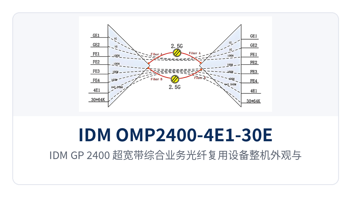
Figure 1: Photo of the IDM GP-2400 ultra-broadband integrated service optical multiplexing equipment, showing the unit's appearance and indicator LEDs
E1 Transparent Transmission and Gigabit Ethernet Multiplexing: Three Types of Services in Integrated Access over One Fiber
E1 transparent transmission and gigabit Ethernet multiplexing are performed by the same OMP2400-4E1-30E, so a single integrated service access device can provide E1 leased lines, gigabit Ethernet and telephone audio at the same time, reducing the stacking of multiple devices and duplicated cabling. Each interface is divided into channels according to the service type and complies with the corresponding international standards; the functions are detailed in the following table:
Function | Description |
|---|---|
E1 interface transparent transmission | Supports 2.048Mbps E1 services, line coding HDB3, compliant with ITU-T G.703, impedance 75Ω/120Ω selectable, frame structure PCM30/31, transparent transmission mode does not change the time slot content |
Ethernet interface | Provides an RJ45 interface, transmission rate 10M/100M/1000M, compliant with IEEE802.3, full-duplex/half-duplex auto-negotiation |
Telephone audio interface | Audio range 300Hz~3400Hz, three-element complex impedance 200Ω+560Ω//0.1μF, ITU G.711 A-law compression, loop current 25mA/channel, able to connect to telephone voice channels or audio equipment |
SFP optical interface | The optical port is a pluggable SFP, optical fiber rate 2.5Gbps, single-mode/multi-mode fiber selectable, wavelength 1310nm/1550nm |
Full/half-duplex/adaptive | The Ethernet port automatically negotiates the operating mode according to the capability of the opposite-end device, with no manual configuration required |
Dual power supply | Supports DC-48V and AC220V dual power supply access; a failure of a single power supply does not affect service operation |
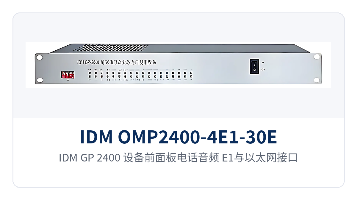
Figure 2: Layout of the telephone audio, E1 and Ethernet interfaces on the front panel of the IDM GP-2400
Key Specifications: Technical Indicators of the 2.5Gbps Optical Multiplexing Equipment
The indicators of the 2.5Gbps optical multiplexing equipment cover six parts: the optical interface, E1 interface, Ethernet interface, audio interface, power supply and power consumption, and environmental conditions; the key parameters are shown in the following table, and the values are subject to the manufacturer's product documentation and factory testing:
Item | Parameter/Specification | Description/Applicable Conditions |
|---|---|---|
Optical interface type | SFP | Pluggable optical module, convenient for replacement and spare parts |
Fiber mode | Single-mode (multi-mode optional) | Selected according to line distance and fiber core conditions |
Optical fiber rate | 2.5Gbps | Shared by E1, Ethernet and telephone audio services |
Wavelength | 1310nm/1550nm | Two wavelengths selectable |
Transmit optical power | -1~-3dBm | Typical single-mode value; subject to actual measurement with an optical power meter |
Receiver sensitivity | Better than -24dBm | The link loss budget can be calculated on this basis |
E1 bit rate | 2048Kbps | Line coding HDB3 |
E1 standard protocol | Supports ITU-T G.703 | Standard E1 interface specification |
E1 impedance | 75Ω/120Ω | Selected according to the interface of the interconnected equipment |
E1 frame structure | PCM30/31 | Primary group frame structure |
E1 mode | Transparent transmission | Services are transmitted as they are, without changing the time slot content |
Ethernet transmission rate | 10M/100M/1000M | Compliant with IEEE802.3, full/half-duplex/adaptive |
Audio range | 300Hz~3400Hz | Telephone voice channel bandwidth |
Audio impedance | Three-element complex impedance 200Ω+560Ω//0.1μF | Telephone subscriber line interface standard |
Audio compression | A-law in ITU G.711 | 64Kbps PCM encoding |
Audio loop current | 25mA/channel | Feeding capability of each voice channel |
Power supply mode | DC-48V / AC220V / dual power supply | Dual power supply access improves power supply reliability |
Overall power consumption | ≤100W | Overall value including service boards and optical modules |
Operating temperature | 0℃~40℃ | Equipment room environment |
Humidity | ≤90% (non-condensing) | Upper limit of relative humidity |
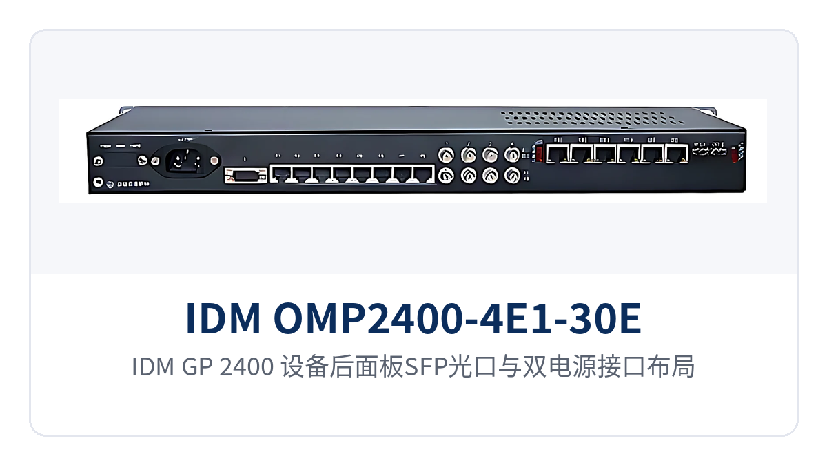
Figure 3: Layout of the SFP optical ports and dual power supply interfaces on the rear panel of the IDM GP-2400
Typical Application Scenarios
Electric Power Private Network: Telephone, Automation E1 and In-Station Data Backhaul Between Substations and Dispatch Stations
Between electric power substations and dispatch stations, dispatch telephones, automation E1 leased lines and in-station Ethernet data usually need to be transmitted at the same time. One OMP2400-4E1-30E is placed at each site, and a pair of 2.5Gbps single-mode fibers multiplexes the inter-station dispatch audio, E1 channels and data services, replacing the stacking of multiple devices and the renting of multiple lines. The audio interface of the equipment complies with ITU G.711 A-law with a loop current of 25mA/channel and can interconnect directly with dispatch voice channel equipment; the E1 interface uses transparent transmission in accordance with ITU-T G.703, and the dispatch switches and relay protection devices at the opposite end usually need no configuration adjustments.
Rail Transit Private Network: E1 Channels, Official Telephones and Broadband Data Backhauled over One Fiber Between Stations and Depots
Between rail transit stations, depots and the stations along the line, the E1 channels of official telephones, signaling systems and ticketing equipment as well as surveillance data are often scattered over different cables. The OMP2400-4E1-30E multiplexes the telephone voice channels, 4 groups of E1 channels and gigabit Ethernet data on the station side onto a pair of fibers for backhaul to the control center, where the opposite-end equipment in the central equipment room restores them and connects them to the existing transmission and switching equipment; only one pair of fiber cores is occupied between stations, which facilitates capacity expansion in sections where existing optical cable resources are tight.
Military and Government Private Networks: Integrated Service Access at Remote Stations and Unattended Equipment Rooms
Remote stations, duty posts and storage areas of military and government private networks often lack on-site maintenance personnel, and their power supply and temperature control conditions are limited. The OMP2400-4E1-30E supports DC-48V and AC220V dual power supply access, with an overall power consumption of no more than 100W, an operating temperature of 0℃~40℃ and a humidity of no more than 90% (non-condensing); it is suitable for deployment in a standard cabinet or equipment room with temperature control, providing E1 leased lines, office Ethernet and internal telephone services over a pair of fibers at the same time.
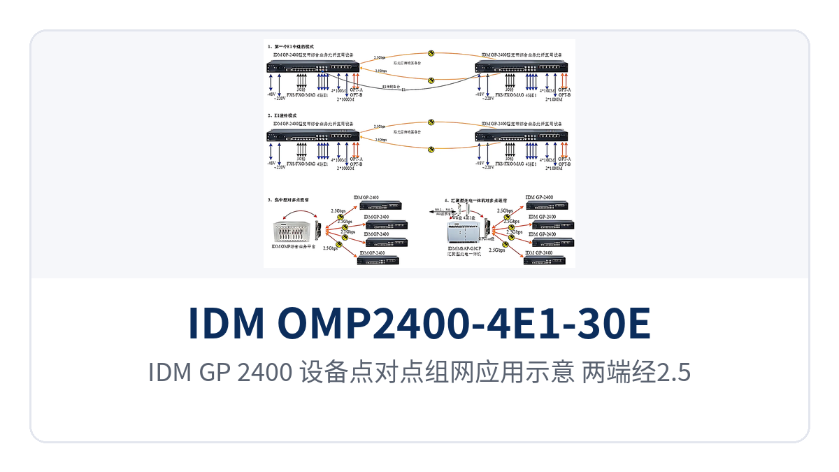
Figure 4: Point-to-point networking application diagram of the IDM GP-2400, with the two ends interconnected by a 2.5G optical fiber
Differentiated Value: 2.5G Optical Fiber, E1 Transparent Transmission, Dual Power Supply and Gigabit Ethernet
The differentiation of the OMP2400-4E1-30E is concentrated in three points: one pair of fibers carrying multiple services, E1 transparent transmission in accordance with the standard to interconnect with existing private networks, and dual power supply access suited to unattended sites. As a PCM equipment oriented to the private network market, the correspondence between these three capabilities and the actual value for private network customers is shown in the following table:
Differentiated selling points | Specific capability | Value for private network customers |
|---|---|---|
2.5G optical fiber carrying multiple services | One pair of single-mode fibers simultaneously carries E1 leased lines, 10M/100M/1000M Ethernet and telephone audio services | Integrated access over one fiber, replacing multiple devices and multiple optical fibers and reducing device stacking and duplicated cabling |
Standard transparent transmission of E1 interfaces | Bit rate 2048Kbps, line coding HDB3, supports ITU-T G.703, frame structure PCM30/31, transparent transmission mode, impedance 75Ω/120Ω | Seamless interconnection with the existing E1 private networks of electric power and rail transit; the opposite-end equipment needs no configuration changes |
DC-48V/AC220V dual power supply | Dual power supply access, overall power consumption ≤100W | Suited to unattended sites; a single power supply failure does not interrupt services |
Dual-Power-Supply Unattended Optical Multiplexing Equipment: -48V/220V Dual-Path Power Feeding and ≤100W Power Consumption
The design focus of dual-power-supply unattended optical multiplexing equipment is to keep services running when a single power path fails. The OMP2400-4E1-30E provides both DC-48V and AC220V power supply access modes; the -48V DC and 220V AC mains commonly used in communications equipment rooms can be connected to the two power paths separately, and when either path fails the other continues to supply power; with an overall power consumption of no more than 100W, it can be deployed as a 1U chassis at an unattended site, with low requirements on equipment room air conditioning and storage battery capacity.
How to Select Multi-Service Optical Multiplexing Equipment over One Fiber: Three Items to Verify
To select multi-service optical multiplexing equipment over one fiber, three items can be verified one by one to close the loop: the number of service channels, the optical fiber line conditions, and the power supply and equipment room environment. First verify the service types and number of channels: confirm how many groups of E1 channels, how many channels of telephone audio and how many Ethernet ports are required, and compare them item by item with the 4 groups of E1 and 30 channels of telephone audio of the OMP2400-4E1-30E; if the number of channels does not match, confirm other configuration models of the same series with the optical multiplexer manufacturer. Then verify the optical fiber line conditions: confirm whether single-mode or multi-mode is used, whether the wavelength is 1310nm or 1550nm, and how much the line loss budget is, and determine the distance grade of the SFP optical module after calculating on the basis of the transmit optical power of -1~-3dBm and the receiver sensitivity better than -24dBm. Finally verify the power supply and environment: DC-48V, AC220V or a dual power supply must match the site power supply, the ambient temperature is 0℃~40℃ and the humidity does not exceed 90% (non-condensing), and deployment in a standard equipment room or a cabinet with temperature control is recommended. After the OMP2400-4E1-30E is powered on, first confirm that the optical port indicator LED shows normal received optical power, then verify the E1, Ethernet and voice channel services one by one, which shortens the commissioning time.
Conclusion
The IDM OMP2400-4E1-30E ultra-broadband integrated service optical multiplexing equipment uses a 2.5Gbps optical fiber to carry 4 groups of E1, gigabit Ethernet and 30 channels of telephone audio services at the same time; the E1 interface uses transparent transmission in accordance with ITU-T G.703, the Ethernet interface complies with IEEE802.3, and the audio is encoded according to ITU G.711 A-law, and the equipment supports DC-48V/AC220V dual power supply with an overall power consumption of ≤100W, which suits multi-service-over-one-fiber access for electric power, rail transit and military and government private networks. As a professional optical multiplexer manufacturer and SDH equipment manufacturer, Raytrans also provides government private network optical fiber communication solutions and military emergency communications vehicle solutions; during selection, first verify the number of service channels and the board configuration, then calculate the link loss budget, confirm the site power supply and environmental conditions, and confirm the final configuration and quotation with the manufacturer.
Item | Parameter/Specification | Description/Applicable Conditions |
|---|---|---|
Optical interface type | SFP | Pluggable optical module, convenient for replacement and spare parts |
Fiber mode | Single-mode (multi-mode optional) | Selected according to line distance and fiber core conditions |
Optical fiber rate | 2.5Gbps | Shared by E1, Ethernet and telephone audio services |
Wavelength | 1310nm/1550nm | Two wavelengths selectable |
Transmit optical power | -1~-3dBm | Typical single-mode value; subject to actual measurement with an optical power meter |
Receiver sensitivity | Better than -24dBm | The link loss budget can be calculated on this basis |
E1 bit rate | 2048Kbps | Line coding HDB3 |
E1 standard protocol | Supports ITU-T G.703 | Standard E1 interface specification |
E1 impedance | 75Ω/120Ω | Selected according to the interface of the interconnected equipment |
E1 frame structure | PCM30/31 | Primary group frame structure |
E1 mode | Transparent transmission | Services are transmitted as they are, without changing the time slot content |
Ethernet transmission rate | 10M/100M/1000M | Compliant with IEEE802.3, full/half-duplex/adaptive |
Audio range | 300Hz~3400Hz | Telephone voice channel bandwidth |
Audio impedance | Three-element complex impedance 200Ω+560Ω//0.1μF | Telephone subscriber line interface standard |
Audio compression | A-law in ITU G.711 | 64Kbps PCM encoding |
Audio loop current | 25mA/channel | Feeding capability of each voice channel |
Power supply mode | DC-48V / AC220V / dual power supply | Dual power supply access improves power supply reliability |
Overall power consumption | ≤100W | Overall value including service boards and optical modules |
Operating temperature | 0℃~40℃ | Equipment room environment |
Humidity | ≤90% (non-condensing) | Upper limit of relative humidity |
Figure 3: Layout of the SFP optical ports and dual power supply interfaces on the rear panel of the IDM GP-2400
Typical Application Scenarios
Electric Power Private Network: Telephone, Automation E1 and In-Station Data Backhaul Between Substations and Dispatch Stations
Between electric power substations and dispatch stations, dispatch telephones, automation E1 leased lines and in-station Ethernet data usually need to be transmitted at the same time. One OMP2400-4E1-30E is placed at each site, and a pair of 2.5Gbps single-mode fibers multiplexes the inter-station dispatch audio, E1 channels and data services, replacing the stacking of multiple devices and the renting of multiple lines. The audio interface of the equipment complies with ITU G.711 A-law with a loop current of 25mA/channel and can interconnect directly with dispatch voice channel equipment; the E1 interface uses transparent transmission in accordance with ITU-T G.703, and the dispatch switches and relay protection devices at the opposite end usually need no configuration adjustments.
Rail Transit Private Network: E1 Channels, Official Telephones and Broadband Data Backhauled over One Fiber Between Stations and Depots
Between rail transit stations, depots and the stations along the line, the E1 channels of official telephones, signaling systems and ticketing equipment as well as surveillance data are often scattered over different cables. The OMP2400-4E1-30E multiplexes the telephone voice channels, 4 groups of E1 channels and gigabit Ethernet data on the station side onto a pair of fibers for backhaul to the control center, where the opposite-end equipment in the central equipment room restores them and connects them to the existing transmission and switching equipment; only one pair of fiber cores is occupied between stations, which facilitates capacity expansion in sections where existing optical cable resources are tight.
Military and Government Private Networks: Integrated Service Access at Remote Stations and Unattended Equipment Rooms
Remote stations, duty posts and storage areas of military and government private networks often lack on-site maintenance personnel, and their power supply and temperature control conditions are limited. The OMP2400-4E1-30E supports DC-48V and AC220V dual power supply access, with an overall power consumption of no more than 100W, an operating temperature of 0℃~40℃ and a humidity of no more than 90% (non-condensing); it is suitable for deployment in a standard cabinet or equipment room with temperature control, providing E1 leased lines, office Ethernet and internal telephone services over a pair of fibers at the same time.
Figure 4: Point-to-point networking application diagram of the IDM GP-2400, with the two ends interconnected by a 2.5G optical fiber
Differentiated Value: 2.5G Optical Fiber, E1 Transparent Transmission, Dual Power Supply and Gigabit Ethernet
The differentiation of the OMP2400-4E1-30E is concentrated in three points: a pair of fibers carrying multiple services, E1 transparent transmission in accordance with standards for interconnection with existing private networks, and dual power supply for unattended sites. As a PCM equipment oriented to the private network market, its three capabilities correspond to the actual value for private network customers as shown in the following table:
Differentiated selling points | Specific capability | Value for private network customers |
|---|---|---|
2.5G optical fiber carrying multiple services | A pair of single-mode fibers simultaneously carries E1 leased lines, 10M/100M/1000M Ethernet and telephone audio services | Integrated access over one fiber, replacing multiple devices and multiple optical fibers and reducing device stacking and duplicated cabling |
Standard transparent transmission of E1 interfaces | Bit rate 2048Kbps, line coding HDB3, supports ITU-T G.703, frame structure PCM30/31, transparent transmission mode, impedance 75Ω/120Ω | Seamless interconnection with the existing E1 private networks of electric power and rail transit; the opposite-end equipment needs no configuration changes |
DC-48V/AC220V dual power supply | Dual power supply access, overall power consumption ≤100W | Suited to unattended sites; a single power supply failure does not interrupt services |
Dual-Power-Supply Unattended Optical Multiplexing Equipment: -48V/220V Dual-Path Power Supply and ≤100W Power Consumption
The design focus of dual-power-supply unattended optical multiplexing equipment is to keep services running when a single power path fails. The OMP2400-4E1-30E provides both DC-48V and AC220V power supply access modes; the -48V DC and 220V AC mains commonly used in communications equipment rooms can be connected to the two power paths separately, and when either path fails the other continues to supply power; with an overall power consumption of no more than 100W, it can be deployed as a 1U chassis at an unattended site, with low requirements on equipment room air conditioning and storage battery capacity.
How to Select Multi-Service Optical Multiplexing Equipment over One Fiber: Three Items to Verify
To select multi-service optical multiplexing equipment over one fiber, three items can be verified one by one to close the loop: the number of service channels, the optical fiber line conditions, and the power supply and equipment room environment. First verify the service types and number of channels: confirm how many groups of E1 channels, how many channels of telephone audio and how many Ethernet ports are required, and compare them item by item with the 4 groups of E1 and 30 channels of telephone audio of the OMP2400-4E1-30E; if the number of channels does not match, confirm other configuration models of the same series with the optical multiplexer manufacturer. Then verify the optical fiber line conditions: confirm whether single-mode or multi-mode is used, whether the wavelength is 1310nm or 1550nm, and how much the line loss budget is, and determine the distance grade of the SFP (small form-factor pluggable) module after calculating on the basis of the transmit optical power of -1~-3dBm and the receiver sensitivity better than -24dBm. Finally verify the power supply and environment: DC-48V, AC220V or a dual power supply must match the site power supply, the ambient temperature is 0℃~40℃ and the humidity does not exceed 90% (non-condensing), and deployment in a standard equipment room or a cabinet with temperature control is recommended. After the OMP2400-4E1-30E is powered on, first confirm that the optical port indicator LED shows normal received optical power, then verify the E1, Ethernet and voice channel services one by one, which shortens the commissioning time.
Conclusion
The IDM OMP2400-4E1-30E ultra-broadband integrated service optical multiplexing equipment uses a 2.5Gbps optical fiber to carry 4 groups of E1, gigabit Ethernet and 30 channels of telephone audio services at the same time; the E1 interface uses transparent transmission in accordance with ITU-T G.703, the Ethernet interface complies with IEEE802.3, and the audio is encoded according to ITU G.711 A-law, and the equipment supports DC-48V/AC220V dual power supply with an overall power consumption of ≤100W, which suits multi-service-over-one-fiber access for electric power, rail transit and military and government private networks. As a professional optical multiplexer manufacturer and SDH equipment manufacturer, Raytrans also provides government private network optical fiber communication solutions and military emergency communications vehicle solutions; during selection, first verify the number of service channels and the board configuration, then calculate the link loss budget, confirm the site power supply and environmental conditions, and confirm the final configuration and quotation with the manufacturer.