
IDM-NT008
IDM-NT008
The IDM-NT008 Desktop 8-Channel Multi-Service Optical Multiplexer provides 8 telephone interfaces through 1 optical fiber channel. The 8-channel telephone optical multiplexer features high integration and compact size. It extends voice and data services to various user areas, enabling cross-boundary number assignment, serving as a substitute for remote small exchanges, and postponing the construction of switching offices. Alternatively, in urban areas, it overcomes the limitations of twisted pair in terms of frequency band and transmission distance, expanding the service range of switching offices.
Overview:
The IDM-NT008 integrated service fiber access device is one of the integrated service transmission multiplexing devices designed by our company using dedicated large-scale integrated circuits. The IDM-NT008 telephone optical terminal connects user terminal equipment or user terminal equipment to the public switched telephone network through fiber optic transmission media.
The IDM-NT008 telephone optical terminal extends voice and data services to various subscriber areas, enabling cross-boundary number assignment, serving as a substitute for remote small exchanges, and deferring the construction of switching offices. Alternatively, it resolves the limitations of twisted pair in bandwidth and transmission distance within urban areas, expanding the service coverage of switching offices.
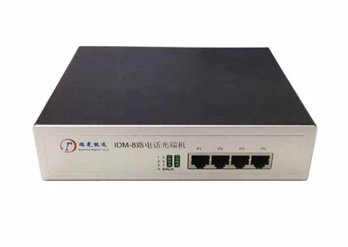
Indicator light description
Indicator Name | Definition | Status Description |
1 | Channel 1 Telephone Indicator | Steady ON: Telephone in use; Blinking: Ringing; OFF: Channel idle |
2 | Channel 2 Telephone Indicator | Steady ON: Telephone in use; Blinking: Ringing; OFF: Channel idle |
3 | Channel 3 Telephone Indicator | Steady ON: Telephone in use; Blinking: Ringing; OFF: Channel idle |
4 | Channel 4 Telephone Indicator | Steady ON: Telephone in use; Blinking: Ringing; OFF: Channel idle |
5 | Channel 5 Telephone Indicator | Steady ON: Telephone in use; Blinking: Ringing; OFF: Channel idle |
6 | Channel 6 Telephone Indicator | Steady ON: Telephone in use; Blinking: Ringing; OFF: Channel idle |
7 | Channel 7 Telephone Indicator | Steady ON: Telephone in use; Blinking: Ringing; OFF: Channel idle |
8/ALM | Channel 8 Telephone Indicator | Steady ON: Telephone in use; Blinking: Ringing; OFF: Channel idle |
Fiber Optic Alarm | Blinking: Fiber optic alarm; Normal operation: OFF |
Table 1-1
Telephone Interface Pin Assignment
Interface | 8P8C RJ45 Pin | Definition |
P1-P4 | 4 5 | Channel 1 |
3 6 | Channel 2 |
Table 1-2
FXO, FXS Interfaces
Audio Range | 300Hz–3400Hz | Compression | ITU G.711 A-law |
Impedance | Triple compound impedance 200Ω+560Ω//0.1μF | Loop Current | 25mA/channel |
Fiber Connection
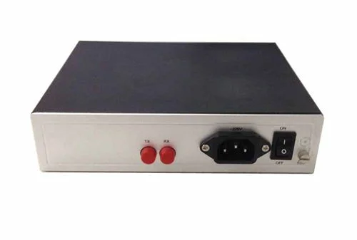
The fiber access ports of the telephone optical transceiver are designated as TX and RX. There are three interface types available. Please specify the connector type in your order based on the fiber cable connector used. If no special requirement is indicated, FC connectors are configured by default. The standard transmission distance is 30–40 km.
Connect TX to the remote end's RX, and RX to the remote end's TX. When the remote device is powered on and the fiber link is properly connected, the 8/ALM green LED on the device remains off. If the 8/ALM indicator flashes, it indicates a fiber link fault — please re-check the fiber connections.
Telephone Not Working
- Check whether the local and remote devices are installed correctly — the local (central office) unit connects to the PBX/switch, and the remote unit connects to the telephone set.
- Check whether the wiring sequence of the service interface is correct.
- Check the fiber link — the 8/ALM indicators on both ends should remain steadily off to confirm the fiber link is normal.
- Check whether the telephone set itself is functioning properly.
FAQs
Top 10 Common Questions About Telephone Optical Terminals
Based on years of experience in the production and R&D of telephone optical terminals…
View answerHow to Troubleshoot Common Faults of Telephone Optical Terminal?
Device cannot be powered on Check whether the power cable is connected correctly.
View answerWhat is an Optical Terminal?
Many people are unfamiliar with the optical terminal, but in essence, it is a dedicated device for optical-electrical…
View answer