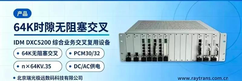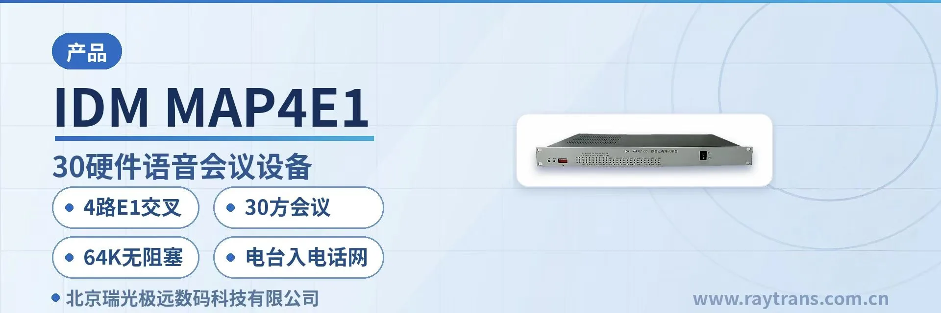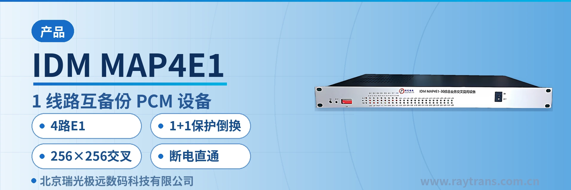
IDM MAP4E1 4xE1 Line Mutual Backup PCM Equipment
4xE1
The IDM MAP4E1 4xE1 line mutual backup PCM equipment uses 2M cables as the transmission medium and provides four E1 transmissions externally; the first and second E1s support 1+1 protection switching, and the third and fourth E1s support 1+1 protection switching. It supports point-to-point transmission and point-to-multipoint transmission
The IDM MAP4E1 4-group E1 line mutual-backup PCM equipment is a PCM multiplexer that uses 2M cables as the transmission medium and provides four E1 channels externally. Developed by Beijing Ruiguang Jiyuan Digital Technology Co., Ltd. (Raytrans), it multiplexes 64K services such as telephone, audio, serial port data, and Ethernet onto E1 channels for transmission, making it a typical PCM equipment for private network scenarios.
The unit provides 15 user card slots in a 19-inch 1U chassis, with each card carrying 2 channels of 64K service and a fully configured capacity of 30 channels of 64K service. On the line side, E1 channels 1 and 2 and E1 channels 3 and 4 each form a pair for 1+1 protection switching (E1 protection switching), with the two pairs independent of each other.
The four E1 channels can each point to a different transmission direction, facilitating chain and star network topologies; when protection is required, two of them are configured as a pair, and services are carried by the backup link after the primary link fails. Service cards are selected according to the on-site service list, and telephone, magneto, EM audio, RS232/RS485 serial port, and 10/100Base-T Ethernet can all be connected to the same unit, so a site does not need a separate converter for each service type. The unit incorporates a time-slot cross-connect equipment with 256×256 cross-connect capability and a power failure pass-through design, enabling flexible scheduling of 64K time slots and ensuring service continuity during link interruption. It is suitable for product showcase scenarios with high reliability requirements, such as government private network optical fiber communication solutions and military emergency communications vehicle solutions.
Key Specifications at a Glance: 4xE1 · 1+1 protection switching · 256×256 cross-connect · power failure pass-through · 15 card slots · 30 channels of 64K at full configuration · ≤10W per unit
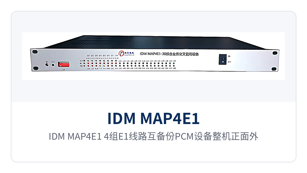
Figure 1: Front view, alarm indications, and function control switches of the IDM MAP4E1 4-group E1 line mutual-backup PCM equipment
What is the 4-group E1 line mutual-backup PCM equipment?
The 4-group E1 line mutual-backup PCM equipment is a multiplexer that combines narrowband service access and E1 line transmission in one unit: the user side connects to telephones, audio, and data terminals, while the line side connects to E1 channels, with services packed into 2048Kbps E1 time slots according to the PCM30/32 frame structure. As a typical PCM equipment, its E1 interface uses HDB3 line coding, and the interface specifications comply with ITU-T G.703, G.706, G.823, and G.742 recommendations.
A complete unit consists of a 19-inch 1U chassis, a main control card, and service cards. The transmission signal processing for all four E1 channels is concentrated on a single chip, reducing internal wiring and component count. The equipment complies with ITU-T G.703, G.704/98, G.706, and G.732 protocols and interfaces with existing E1 transmission networks and switching equipment according to the interface specifications of PCM base group multiplexing equipment.
How are E1 time slots allocated to each service?
The 2048Kbps E1 is divided according to the PCM30/32 frame structure, with 32 time slots per frame, of which TS0 is used for frame alignment and TS16 for channel-associated signaling (CAS), while the remaining 30 time slots each carry one channel of 64K service. Service cards occupy time slots at single-time-slot granularity; a card providing two services occupies two time slots, and 30 channels of 64K service exactly fill the available time slots of one E1.
How does 4xE1 achieve pairwise 1+1 protection switching?
E1 protection switching is implemented by pairing E1 channels 1 and 2 and pairing E1 channels 3 and 4, with the same batch of services sent simultaneously over the primary and backup links; when the primary link alarms or is interrupted, services are carried by the backup link. The two pairs are independent of each other, so a failure on one pair does not affect the other, and sites can configure them separately according to service importance.
The protection switching criterion is derived from the alarm state of the E1 line, and the front panel displays master/slave clock (CLK), loss of signal (LOS), out of frame (OOF), alarm indication signal (AIS), and remote alarm indication (RAI) for each E1 channel. On-duty personnel can see which link is abnormal directly from the front of the equipment without first logging into the network management system to check site by site.
How do the four E1 directions form chain and star networks?
The four E1 channels transmit and receive independently, and link routes are not restricted by the pairing relationship; configuring a protection pair is only one way to use them. When sites are connected end to end, multiple E1 channels are used to form a chain network; when connecting a central station to branch sites, a star network is used. The same unit can serve as an intermediate node in a chain or as the central node of a star, switching flexibly between chain and star networking.
When the networking topology changes, only the E1 wiring and the device operating mode are changed, while the chassis and service cards remain untouched. DIP switches allow quick setting of the device clock, operating mode, E1 loopback, and site address, so on-site adjustment requires neither a computer nor opening the chassis. DIP switch settings must be consistent with network management settings, and should be rechecked in the network management system after changes.
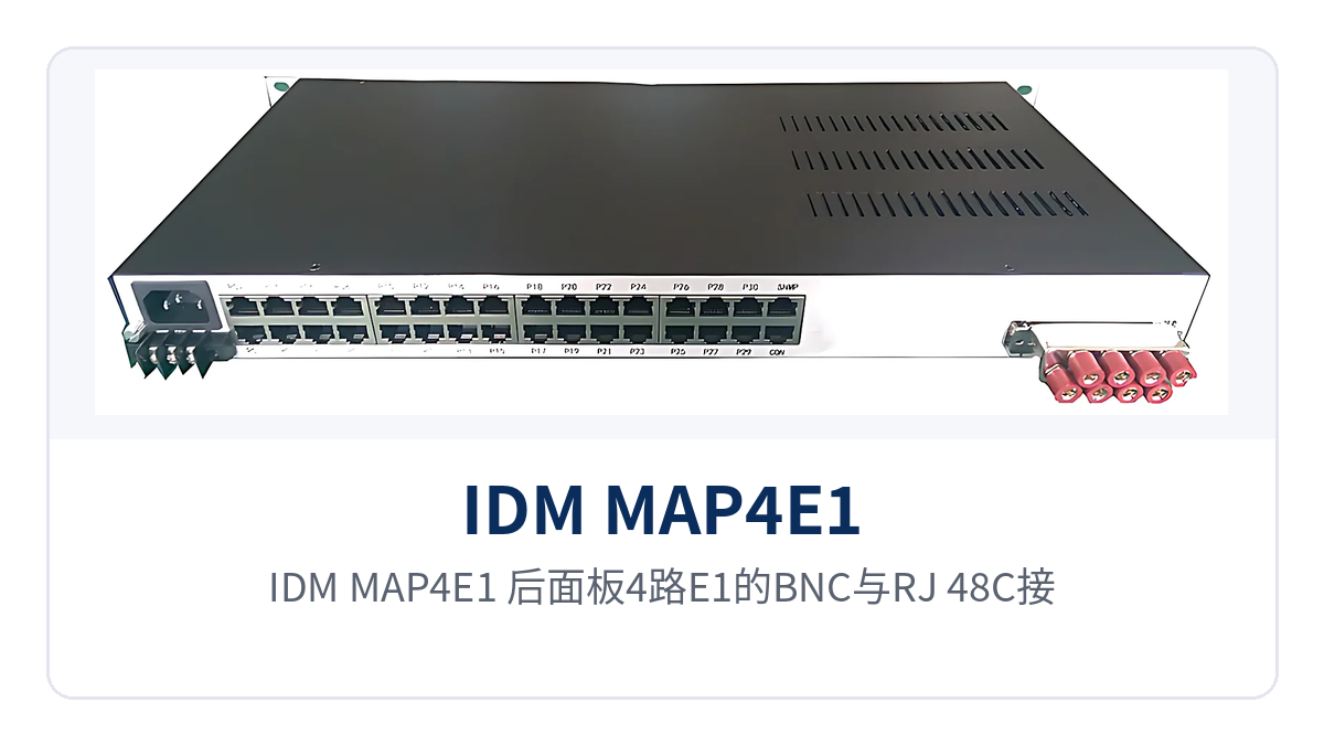
Figure 2: BNC and RJ-48C interfaces for the four E1 channels, service interfaces, and AC/DC power wiring area on the rear panel of the IDM MAP4E1
How is the 256×256 time-slot cross-connect matrix used?
The 256×256 time-slot cross-connect matrix allows every time slot between the four E1 channels and the user interfaces to be cross-connected, enabling data and signaling cross-connection from user to user, user to line, and line to line. The four E1 directions each have 32 time slots, totaling 128 time slots, while the user side occupies additional time slots for 30 services; the matrix capacity is sufficient for these time slots to participate in cross-connection simultaneously.
Cross-connection relationships are set via network management or DIP switches; when a service needs to be redirected to another direction, only the time slot configuration is changed, without touching the wiring. This capability allows one unit to also serve as 4xE1 time-slot cross-connect equipment: where a site previously needed a multiplexer plus a cross-connect device in series, one 1U device now does both.
Will changing the cross-connect configuration affect services in operation?
Time slots are allocated on demand for cross-connection, and only the modified time slots are rearranged while connections of other time slots remain unaffected, so services in operation continue along their original paths. The network management system supports time slot reallocation, configuration query, alarm query, and fault location, allowing the connection relationships before and after changes to be compared and confirmed in the network management system, with services verified one by one after the change.
What on-site problems do power failure pass-through and voice port protection solve?
When the equipment loses power, the E1 upstream and downstream are passed through, and the line signal bypasses directly from upstream to downstream, so other sites on the link are not disconnected because one device loses power. The internal circuit passes through the E1 transmit and receive ports in the power-off state and automatically returns to the normal multiplexing state when power is restored, without manual intervention.
Voice interfaces are protected against overcurrent and overvoltage; overvoltage energy from lightning or coupled onto the line is discharged at the interface rather than directly striking the voice channel chip. At sites with ordinary power supply and grounding conditions, such as outdoor cabinets, along-route locations, and older equipment rooms, interface protection determines whether the equipment is destroyed by a single surge or can continue to operate.
How does PCM equipment power failure pass-through manifest in networking?
In a chain network, each device is a node on the path, and any device losing power cuts the link into two segments, causing upstream and downstream sites to lose contact. E1 upstream/downstream pass-through connects the line side of the powered-off node, so voice and data from the remaining sites on the chain can still be delivered, and services need not be entirely interrupted during repair.
Which service cards can the 15 card slots be configured with?
Each of the 15 user card slots can hold a 2-channel single-time-slot card, and more than 20 types of interface cards can be mixed in the chassis, with service types combined according to the on-site service list. Cards are paired at the transmit and receive ends by service: whatever interface is provided at one end, the corresponding interface is configured at the other end; for voice services, it also matters whether the opposite end is the exchange side or the telephone side.
| Service Card | Interface Capability | Typical Connected Device |
|---|---|---|
| 10/100Base-T Ethernet card | Provides 10/100Base-T Ethernet interfaces, with data carried in 64K time slots | Site data terminals, monitoring and network management data |
| Ordinary telephone card (FXO) | Central office interface, supporting polarity reversal and caller ID (CID) | Exchange subscriber lines, private network exchange side |
| Ordinary telephone card (FXS) | Remote interface, supporting polarity reversal and caller ID (CID) | Analog telephones, fax machines |
| EM 2/4-wire audio card | 2-wire or 4-wire audio interface | Audio trunks, broadcast and PA equipment |
| Hotline telephone card | Hotline interface with standard signaling tones, connecting to the opposite end upon going off-hook | Dispatch consoles, emergency telephones |
| Ordinary magneto card | Magneto telephone interface | Magneto telephones, legacy dispatching exchanges |
| 2100Hz magneto carrier trunk card | 2100Hz carrier signaling trunk interface | Magneto carrier trunk links |
| V.24/V.28 card | RS232/RS485 serial port | Telecontrol terminals, serial port acquisition devices |
| G.703 64K codirectional data card | 64K codirectional data interface | Relay protection, telecontrol data |
| X.50 sub-rate multiplexing card | Sub-rate multiplexing, packing low-speed data into 64K time slots | Low-speed data centralized upload |
| K interface access card | Four rates: 16Kbit/s, 32Kbit/s, 64Kbit/s, and 128Kbit/s | Electric power protection and telecontrol channels |
Service cards are registered in the network management system by slot position and site address; for capacity expansion, cards are simply added to empty slots while the chassis and existing E1 lines remain unchanged. Voice cards and data cards share the same set of slots, and card positions and time slot allocations correspond item by item in the network management system. Interface types and quantities are determined by the project list, and the interface forms of cards and opposite-end devices are subject to the ordering configuration sheet. With the flexible card configuration capability shown in the above product showcase, the Raytrans series PCM products can be widely adapted to diverse networking scenarios such as government private network optical fiber communication solutions and military emergency communications vehicle solutions.
What are the core functions?
The functions cover four parts: E1 line transmit/receive, service access, time-slot cross-connection, and network management and maintenance, listed item by item in the table below. During selection, compare each item against the services actually required by the project; function items not needed can be left unconfigured. The correspondence between function items and interface standards is also listed for item-by-item checking against the ordering configuration sheet.
| Function | Description |
|---|---|
| 4xE1 transmit/receive | E1 line transmit/receive in four transmission directions, supporting point-to-point and point-to-multipoint transmission |
| 1+1 protection switching | E1 channels 1 and 2 form a protection pair, and E1 channels 3 and 4 form a protection pair; services are carried by the backup link when the primary link fails, implementing E1 protection switching |
| 256×256 cross-connect | Built-in 256×256 time-slot cross-connect matrix, supporting user-to-user, user-to-line, and line-to-line cross-connection |
| Power failure pass-through | E1 upstream and downstream are passed through when the equipment loses power, so other sites on the link are not interrupted |
| Voice port protection | Overcurrent and overvoltage protection for voice interfaces, suppressing overvoltage energy coupled onto the line |
| Service access | 15 card slots, each holding a 2-channel single-time-slot card, 30 channels of 64K service at full configuration, configurable with more than 20 types of interface cards |
| Clock mode | The master clock uses the local clock; the line clock is recovered from E1 channels 1 to 4 |
| Network management channel | Network management occupies the sabit of TS0 or a designated time slot among TS1-TS31, enabling status monitoring of devices across the network |
| Network management functions | RS232 network management interface and IP network management interface, supporting configuration, query, fault location, alarm query, and time slot reallocation |
| DIP switch settings | Quick setting of device clock, operating mode, E1 loopback, and site address |
| Panel alarms | CLK, LOS, OOF, AIS, and RAI displayed for each E1 channel; alarm sound can be muted with a button |
| Online upgrade | Supports online upgrade of the device's low-level program without removing the unit and returning it to the factory |
Technical Specifications
The parameters are listed in the table below in four groups: interface, cross-connect, network management, and power supply. Values are taken from product documentation; items marked as missing are subject to the accompanying technical documentation and the ordering configuration sheet, and are not inferred from the parameters of other models. If the project supply configuration differs from this table, the ordering configuration sheet prevails.
| Item | Parameter/Specification | Description/Applicable Conditions |
|---|---|---|
| Device model | IDM MAP4E1 | 4-group E1 line mutual backup PCM equipment |
| Transmission medium | 2M cable | External interface on the line side of the device |
| Number of E1 channels | 4-channel | Channels 1 and 2 form one pair, channels 3 and 4 form another pair, each with 1+1 protection switching |
| E1 rate and line coding | 2048Kbps, HDB3 | Compliant with ITU-T G.703 |
| E1 interface connector | BNC or RJ-48C | Selected according to the interface form of the opposite end |
| E1 jitter specification | Compliant with ITU-T G.703, G.706, G.823, G.742 | Jitter tolerance, transfer characteristics, and output jitter per the recommendations |
| Protocol standards | G.703, G.704/98, G.706, G.732 | PCM base group multiplexer |
| User card slots | 15, each slot holds 2 single-time-slot cards | Full configuration supports 30 channels of 64K service |
| Cross-connect matrix | 256×256 time slots | User-to-user, user-to-line, line-to-line |
| Clock mode | Master clock, line clock | The line clock is recovered from E1 channels 1 to 4 |
| Service card types | More than 20 | Ethernet, FXO, FXS, EM 2/4-wire, hotline, magneto, 2100Hz carrier trunk, V.24/V.28, G.703 64K codirectional, X.50, K interface, etc. |
| Network management interface | RS232 network management interface, IP network management interface | Press and hold the MASK key for more than 5 seconds to restore the network management IP to the default configuration |
| Chassis form | 19-inch 1U standard chassis | Can provide 30 subscriber interfaces |
| Power supply format | AC 220V, DC -48V | Selected according to site power supply conditions |
| Total output power | ≤10W | Per the complete unit |
| Operating temperature and humidity | Not yet recorded in the knowledge base | Subject to the accompanying technical documentation and ordering configuration |
In What Order Should On-Site Power-On Commissioning Be Checked?
On-site commissioning proceeds in six steps: power supply, clock, site address, line, cross-connection, and service. Confirm each step before moving to the next, so that multiple changes do not stack up and make the source of a problem hard to locate. The devices at both ends of the same link must be configured with the same time slot table, and verification is performed only after both ends are configured.
- Check the power supply format and grounding: confirm whether the site provides AC 220V or DC -48V, crimp the terminals securely before powering on, and observe the power indicator.
- Set the clock mode: keep only one master clock source in the entire network, set the other sites to line clock, and recover the clock from E1 channels 1 to 4.
- Configure the site address and network management IP: the site address is used by the network management system to distinguish nodes. If the network management IP is misconfigured, press the MASK key for more than 5 seconds to restore the default configuration and reconfigure it.
- Check E1 alarms channel by channel: check CLK, LOS, LOF, AIS, and RAI one by one. LOS means no signal is received, LOF means a signal is received but the frame is out of synchronization, and RAI means the opposite end has reported a failure.
- Check the cross-connections: check the routing of each time slot on the network management system against the service list, and compare the user-to-line and line-to-line connections one by one.
- Verify services one by one: test telephone off-hook calls, serial port data transmission and reception, and Ethernet connectivity item by item, and hand over to operation after confirmation.
Typical Application Scenarios
The difference among the three industries lies in the service card combination and the configuration of protection pairs; the networking is always point-to-point or point-to-multipoint: one device at each end, connected by an E1 channel in between, with services configured symmetrically at both ends. For sites where only one or two pairs of E1 are reserved on the site side and the in-station services are rather mixed, this one terminal, many uses form is exactly what is needed. In the following scenarios, the IDM MAP4E1 from Raytrans, as a PCM equipment, plays a typical role in the product showcase and can flexibly adapt to chain network and star network networking requirements.
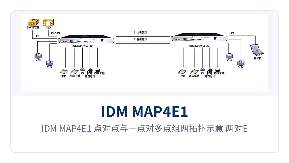
Figure 3: IDM MAP4E1 point-to-point and point-to-multipoint networking topology schematic, with each of the two E1 pairs performing 1+1 protection switching
Electric Power Private Network: Dispatch Telephone and Telecontrol Data Access on the Same Device
Between a substation and the dispatch center there are usually two types of services, dispatch telephone and telecontrol, with E1 channels provided by transmission devices. The IDM MAP4E1 uses FXO or FXS cards to connect dispatch telephones and the exchange side, and V.24/V.28 cards or G.703 64K codirectional data cards to connect telecontrol and protection channels; the two types of services are multiplexed into E1 and sent to the dispatch center. As time-slot cross-connect equipment, its built-in 256×256 cross-connect matrix can complete multi-service time slot allocation on the same PCM equipment.
When E1 channels 1 and 2 come from two different paths, they are configured as a 1+1 protection pair; after one path is interrupted, the dispatch telephone and telecontrol data are carried over the other path, and E1 protection switching keeps services uninterrupted. The in-station cabinet occupies only 1U of space, the service cards are configured according to the bay-level device list, and when measurement and control points are added later, cards are added to empty slots without changing the existing E1 channel and wiring.
Public Security and Military Private Networks: Link Protection and Serial Port Backhaul for Field Sites
Field sites of public security and military are scattered, and links are mostly provided by microwave, leased circuits, or existing transmission networks; in-station services are mainly service function telephones, serial port data, and LAN uplink. The IDM MAP4E1 mixes voice and data into the same unit, presents only a limited number of E1 interfaces externally, and converges the site maintenance surface to one device and one power supply, meeting the requirements of the military emergency communications vehicle solution for compact equipment and consolidated interfaces.
For sites with poor link conditions where a single E1 is susceptible to construction and weather, configure 1+1 protection switching in pairs, so that services automatically switch to the backup link when the primary link degrades. When the device loses power, E1 passes through upstream and downstream, so even if the local site loses power, other sites on the chain can still stay in contact through the pass-through path.
Air Traffic Control and Rail Transit: Point-to-Multipoint Voice and Data Distribution
Sites of air traffic control stations and rail transit section equipment rooms are distributed along the line, and the central station needs to distribute voice and data to multiple remote nodes, with E1 as the main channel. The IDM MAP4E1 acts as a star node at the central station, with four E1 channels pointing in different directions, extending the same link to multiple stations, and is suitable for chain network and star network networking structures.
Remote nodes use magneto cards or EM 2/4-wire audio cards to connect dispatch telephones and broadcast equipment, and serial port cards to connect monitoring data, with interface types selected according to the existing equipment of each station. Time slot cross-connection is allocated at the central station; when a station adds or removes services, only the time slot configuration at the central station and the remote service cards need to be changed, without changing the routing of the entire link. This PCM equipment from Raytrans can also serve as an access layer node in a government private network optical fiber communication solution, working with optical fiber transmission equipment to extend and cross-connect E1 services.
Conclusion
As a 4-group E1 line mutual backup PCM equipment, the Raytrans IDM MAP4E1 packs 1+1 protection switching for the four E1 channels in pairs, 256×256 time slot cross-connection, and 30 channels of 64K service access into a 19-inch 1U chassis: when the primary link is abnormal, services are automatically carried over the backup link; when the site loses power, E1 passes through upstream and downstream; the voice interface has dedicated overcurrent and overvoltage protection; and other sites on the chain do not lose their path due to a single point of failure. This PCM equipment can also be used as time-slot cross-connect equipment, suitable for service access and link protection in government private network optical fiber communication solutions and military emergency communications vehicle solutions, and supports topologies such as chain network and star network networking.
During selection, first determine the service card combination and number of channels required by the product showcase according to the in-station service list, then confirm how many 1+1 protection pairs are needed and whether the device needs to be used as time-slot cross-connect equipment, and finally check whether the site is powered by AC 220V or DC -48V. When networking topology and card configuration recommendations are needed, align each item with the above parameters and the commercial confirmation sheet before ordering.