IDM-30EN Integrated Service Multiplexer
30-Channel Data + 2-Channel Fast Ethernet Same-Fiber Backhaul, 4 Groups of E1 Transparent Transmission, One PC Saved
The IDM-30EN integrated service multiplexer is a device that uses optical fiber as the transmission medium, utilizes standard optical fiber or E1 transmission channels (G.703 standard), and adopts the PCM30/32 format to convert the telephone service signals or data signals to be transmitted into optical signals for transmission over optical fiber to the remote end. In addition to all the services provided by the IDM-30E, it can also provide two Ethernet services. With advantages such as easy installation, simple operation and maintenance and high system reliability, it can be widely applied to public telephone network access or dedicated line information transmission in industries such as telecommunications, electric power, banking and public security.
The 30-channel data + 2-channel Fast Ethernet same-fiber backhaul device refers to an optical multiplexing terminal that simultaneously carries 30 channels of data service and 2 channels of wire-speed 100M Ethernet on the same PCM equipment and backhauls both types of services together to the opposite end over a single optical fiber; the IDM-30EN integrated service multiplexer is a typical device in this category of product showcase: it uses optical fiber as the transmission medium, utilizing standard optical fiber or E1 transmission channels (G.703 standard) and adopting the PCM30/32 format to convert the telephone service signals or data signals to be transmitted into optical signals for transmission to the remote end, and is developed by Beijing Ruiguang Jiyuan Digital Technology Co., Ltd., for public telephone network access or dedicated line information transmission in industries such as telecommunications, electric power, banking and public security.
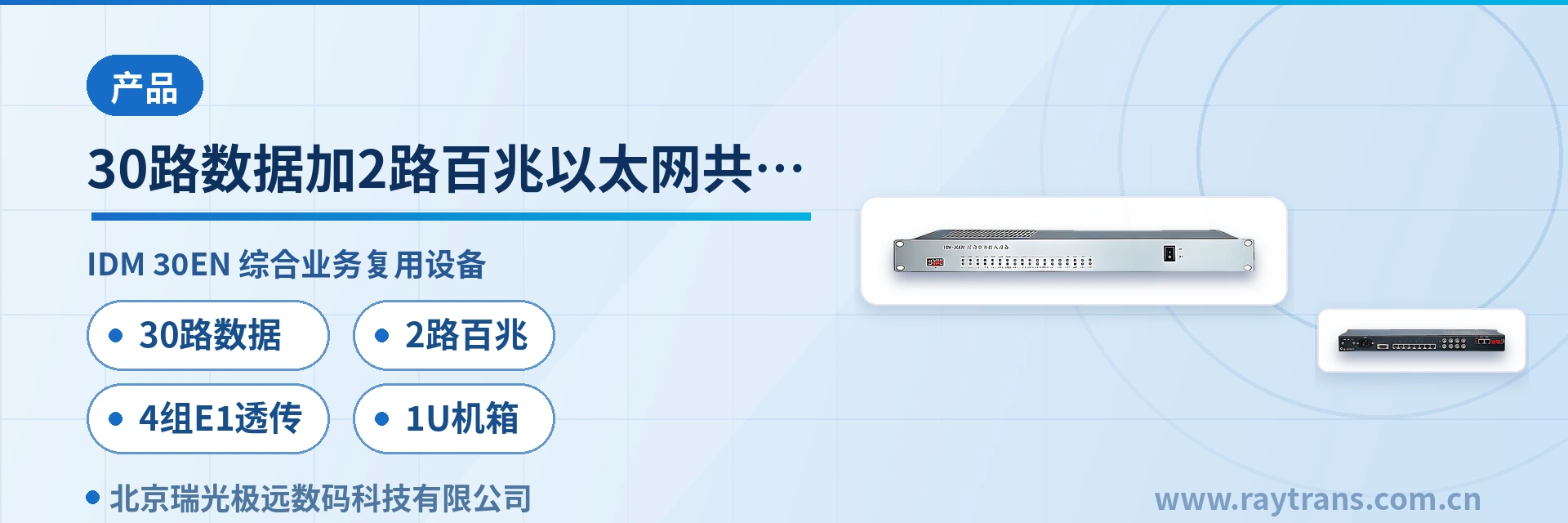
A private network edge site usually needs both narrowband channels such as telephones and telecontrol data and an Ethernet channel that runs service system backhaul. This IDM-30EN integrated service access device combines the two requirements onto the same optical fiber in a single 19-inch 1U device: a single PCM equipment simultaneously carries 30 channels of data service and 2 channels of wire-speed 100M Ethernet, 4 groups of E1 interfaces support transparent transmission and are compatible with the existing G.703 transmission channels on site, and the receiver sensitivity is better than -34dBm with a receive dynamic range of 34dBm, so even long-distance weak optical links run stably. As a professional optical multiplexer manufacturer, Raytrans carries on the reliability design of its government private network optical fiber communication solution in this family of optical multiplexing equipment, so that the integrated service multiplexer covers both narrowband services and Ethernet backhaul requirements in edge access scenarios.
Key Specifications at a Glance: 30 channels of data · 2 channels of Fast Ethernet · 4 groups of E1 transparent transmission · 1U chassis · optical port 155Mbps/1310nm · receiver sensitivity better than -34dBm
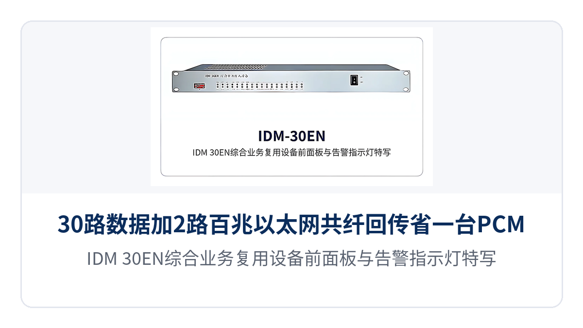
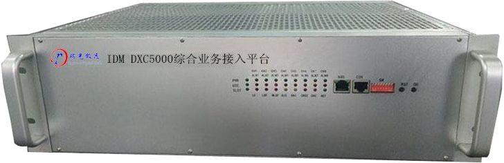
Figure 1: Close-up of the IDM-30EN integrated service multiplexer front panel and alarm indicator LEDs
What Kind of Device Is the IDM-30EN 30-Channel Data + 2-Channel Fast Ethernet Same-Fiber Backhaul Device?
The IDM-30EN 30-channel data + 2-channel Fast Ethernet same-fiber backhaul device is an integrated service access device that multiplexes narrowband services and Ethernet services onto the same optical fiber; the core of the IDM-30EN is to place 30 channels of 64K data service, 2 channels of wire-speed 100M Ethernet and 4 groups of E1 transparent transmission in a 19-inch 1U chassis, and the PCM equipment at the opposite end restores the corresponding telephone or data interfaces after receiving the optical signals.
The IDM-30EN adopts the PCM30/32 format; the E1 interface frame structure, the bit rate of 2048kbit/s±50ppm and the HDB3 line coding are all designed in accordance with the ITU-T G.703 recommendation, so it can directly interconnect with the existing PCM base group links and the spare E1 channels on SDH/PDH links on site; where optical cable is already available on site, a pair of optical multiplexing equipment forms a point-to-point optical fiber link to bring the 30 services and 2 channels of Fast Ethernet of the remote station back to the central equipment room in one pass, which is a common edge access choice in a government private network optical fiber communication solution.
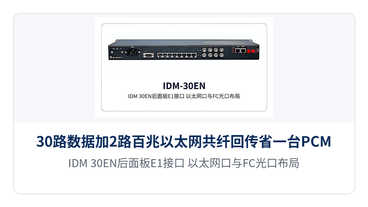
Figure 2: Layout of the E1 interfaces, Ethernet ports and FC optical port on the IDM-30EN rear panel
What Service Interfaces and Functions Does the IDM-30EN Provide?
Function | Description |
|---|---|
Carrying 30 channels of data service | Provides standard 30 data service channels, adopts the PCM30/32 format, and carries telephone or data services in 64K time slots |
2 channels of wire-speed 100M Ethernet | Provides 2 groups of wire-speed 100M Ethernet interfaces with VLAN partitioning support, and the Ethernet can be configured as 4 groups as required on site |
4 groups of E1 interface transparent transmission | 4 groups of E1 interfaces support transparent transmission mode, fully comply with the ITU-T G.703 recommendation, and can reuse existing E1 transmission channels |
64K subscriber interfaces | Provides ordinary telephone cards (FXO, FXS) with caller ID (CID), terminating the 64K time slots as voice channels or data ports |
Clock mode setting | Master clock and user clock can be set, meeting the synchronization requirements of different networking environments such as point-to-point and chain network |
Structured chassis | Adopts a 19-inch 1U standard chassis, facilitating rack installation in a communications equipment room cabinet |
Function control and alarm indication | The panel provides function control switches and alarm indication, facilitating commissioning and routine maintenance |
Which subscriber interfaces the 30 channels of data service of the IDM-30EN can connect depends on the 64K subscriber interface cards fitted on the device: on the voice channel side, ordinary telephone cards (FXO, FXS) with caller ID (CID) can be fitted, with an audio range of 300 Hz to 3400 Hz, compression of A-law in ITU G.711 and a loop current of 25 mA per channel; on the data side, the 64K time slots are terminated as the corresponding data interfaces according to the on-site service types. The 30 64K channels can carry either telephone services or data services, and the specific proportion is determined by the service volume on site.
Technical Specifications and Interface Specifications of the IDM-30EN
Item | Parameter/Specification | Description/Applicable Conditions |
|---|---|---|
E1 interface standard | Fully compliant with the ITU-T G.703 recommendation | Check against this specification when interconnecting with existing PCM base groups and E1 ports on SDH/PDH links |
E1 bit rate | 2048kbit/s±50ppm | 2.048Mbit/s base group rate, with a frequency deviation within ±50ppm |
E1 line coding | HDB3 | Keep consistent with the line coding configuration of the device at the opposite end |
E1 impedance | 75Ω (unbalanced interface)/120Ω (balanced interface) | An external impedance converter is required when using the 120Ω balanced interface |
E1 frame structure | PCM30/32 | 32 time slots per frame, of which 30 time slots carry services |
E1 signaling | Channel-associated signaling (CAS) | Channel-associated signaling mode, transmitted together with the voice channel time slots |
FXO/FXS impedance | Three-element complex impedance 200Ω+560Ω//0.1μF | AC and DC characteristics of the voice channel interface |
FXO/FXS audio range | 300 Hz to 3400 Hz | Voice channel bandwidth, which meets the voice frequency band requirements |
FXO/FXS compression | A-law in ITU G.711 | Voice encoding uses A-law at 64K |
FXO/FXS loop current | 25mA/channel | Loop current feeding each telephone set |
Ethernet interface rate | 10/100M half-duplex and full-duplex | Negotiated according to port capabilities when interconnecting with switches and routers |
Ethernet interface protocol | Compliant with the IEEE-802.3u standard | 100BASE-TX Fast Ethernet specification |
Ethernet interface type | RJ-45 | The port mode is 10/100Mbps adaptive mode |
Optical interface rate | 155Mbps±50ppm | Optical port line rate, corresponding to the 155M optical transmission platform |
Optical interface wavelength | 1310nm | Commonly used operating wavelength for single-mode fiber (SMF); identical at both ends of a paired device |
Optical interface transmit power | -4 to -12 dBm | Used together with the optical path attenuation calculation |
Optical interface receiver sensitivity | Better than -34dBm | Minimum optical power at which the receiver can make a correct decision |
Optical interface receive dynamic range | 34dBm | Adaptation range for weak-signal and strong-signal optical links, especially important for long-distance links |
Optical interface form | FC | Optical port connector type, used with FC pigtails or patch cords |
Power supply mode and overall power consumption | Not yet recorded in the knowledge base | The manufacturer's technical documentation and commercial confirmation shall prevail |
Enclosure specifications | 19-inch 1U standard chassis | Facilitates rack installation in an equipment room cabinet |
Operating environment (temperature, humidity) | Not yet recorded in the knowledge base | The manufacturer's technical documentation and commercial confirmation shall prevail |
How Does Same-Fiber Backhaul Save One PCM Device?
Same-fiber backhaul saves one PCM device by merging narrowband services and Ethernet services onto the same integrated service multiplexer and the same optical fiber, so that one set of transmission equipment is no longer provided for each of the two types of services. One IDM-30EN simultaneously carries 30 channels of data service and 2 channels of wire-speed 100M Ethernet, and a single 19-inch 1U device completes the edge access coverage that previously required two types of equipment, a PCM device plus an Ethernet channel.
What is saved first is equipment and cabinet space. When narrowband services and Ethernet services are transmitted separately, the site usually has to provide one PCM device for the 30 64K services and arrange a separate channel for service system backhaul; the IDM-30EN packs both types of services into one 1U chassis that allows cabinet-to-cabinet installation alongside existing transmission equipment, reducing cabinet space usage and associated cables at the same time.
What is also saved is one optical fiber and one commissioning pass. The IDM-30EN brings 30 channels of data service and 2 channels of Fast Ethernet back to the central equipment room over one optical fiber in one pass; at commissioning, only the E1 line coding and impedance at both ends need to be checked, optical port termination completed and the received optical power confirmed, and the on-site workload falls as the number of devices decreases.
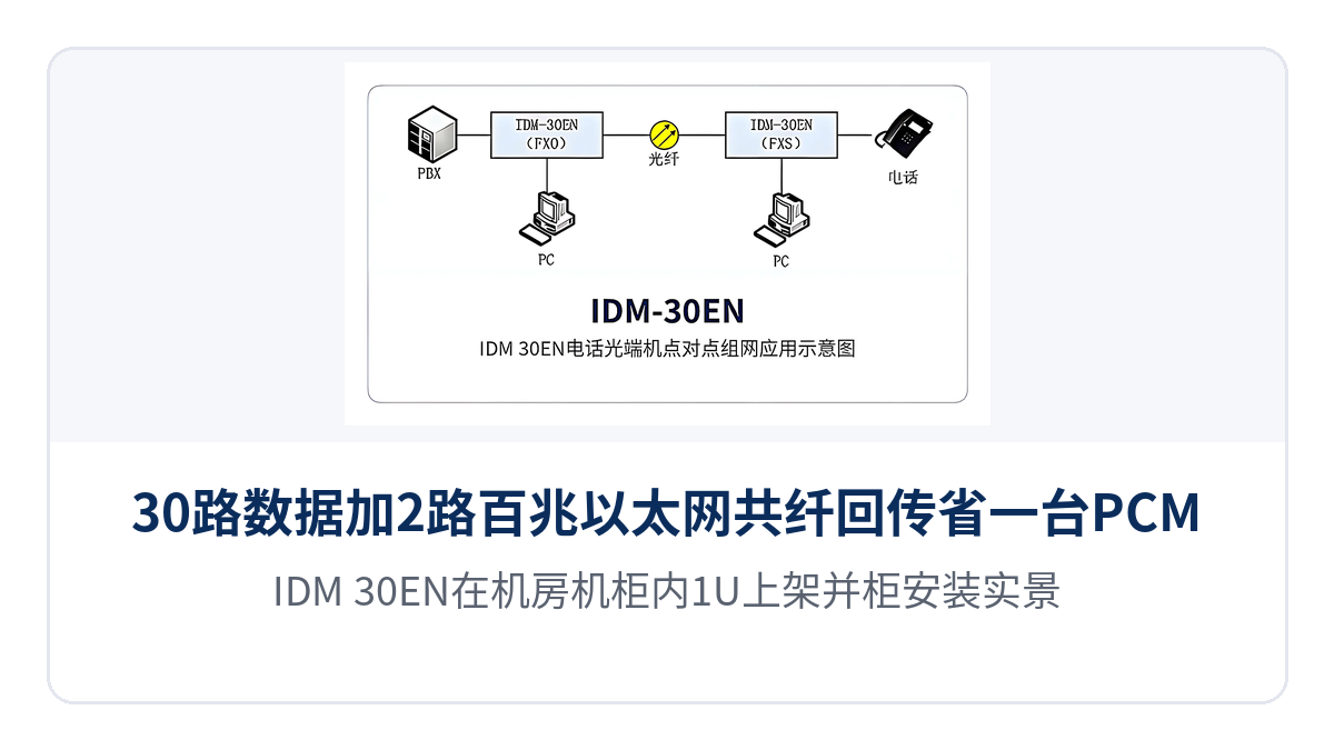
Figure 3: Actual installation view of the IDM-30EN rack-mounted as a 1U unit in an equipment room cabinet
How Does E1 Transparent Transmission Interface with Existing G.703 Links?
E1 transparent transmission interfaces with existing G.703 links by having the 4 groups of E1 interfaces of the IDM-30EN multiplex the existing E1 channels on site in transparent transmission mode: the device forwards the incoming 2.048Mbit/s stream to the opposite end as it is, without parsing or changing the time slots and signaling content in it, so neither the existing link nor the transmission equipment at either end has to be replaced.
Before interfacing, check three items: the line coding is unified as HDB3, the frame structure is unified as the PCM30/32 format, and the impedance is unified as a 75Ω unbalanced interface or a 120Ω balanced interface (an external impedance converter is required when the 120Ω interface is used); the bit rate of 2048kbit/s±50ppm and the signaling mode follow the ITU-T G.703 recommendation, with channel-associated signaling transmitted together with the voice channel time slots.
After interfacing, set the clock mode according to the networking requirements on site: in different networking environments such as point-to-point and chain network, the master clock or the user clock can be set separately to avoid a conflict in the synchronization direction at the two ends. The 4 groups of E1 interfaces correspond one-to-one to the spare E1 ports on the existing link, so during a private network upgrade the configuration only has to match the existing number of channels.
How Does Receiver Sensitivity Affect Link Distance?
Receiver sensitivity has a direct effect on link distance: it determines how much link attenuation the receiver can tolerate and still make a correct decision; the lower the sensitivity value, the greater the permitted optical path attenuation and the longer the usable transmission distance. The receiver sensitivity of the IDM-30EN is better than -34dBm with a receive dynamic range of 34dBm, giving a wider adaptation range for both weak-signal and strong-signal optical links.
In an optical path budget calculation, the transmit optical power of the IDM-30EN is -4 to -12 dBm, which together with the receiver sensitivity better than -34dBm allows a link attenuation of about 22 dB; the actual transmission distance has to be calculated section by section in combination with the attenuation per kilometer of the optical cable, splice point loss and connector loss, and margin should especially be left for long-distance links.
For optical port interfacing, select pigtails or patch cords according to the rate of 155Mbps±50ppm, the wavelength of 1310nm and the FC interface form, keeping the wavelength identical at both ends of a paired device; in engineering practice it is recommended to check the received optical power with an optical power meter before commissioning and to judge whether the link is usable by comparing the actual measurement with the receiver sensitivity specification of the IDM-30EN.
Typical Application Scenarios of the IDM-30EN
Electric Power Private Network: Service Access at Substations and Power Supply Business Halls
Electric power private networks require stable links and simple operation and maintenance. Sites such as substations and power supply business halls usually have both narrowband services such as dispatch telephones and telecontrol data, and also need an Ethernet channel to backhaul service system data. The 30 channels of data service of the IDM-30EN can carry such 64K channels in a concentrated manner, the 2 channels of wire-speed 100M Ethernet meet office and service system backhaul needs, and the 4 groups of E1 interface transparent transmission can reuse the existing G.703 channels on site, so no existing transmission equipment has to be replaced during a link upgrade.
Public Security and Emergency Communications: Bringing Voice and Data Back to the Command Center over One Optical Fiber
Public security and emergency projects have scattered sites and long link distances, and the site often provides only a single optical fiber or one E1 link. The IDM-30EN brings 30 channels of data service and 2 Fast Ethernet channels back to the center over one optical fiber in one pass; with receiver sensitivity better than -34dBm and a receive dynamic range of 34dBm, it handles long-distance links with high optical cable attenuation, and after the device is rack-mounted, commissioning and fault location can be completed through the function control switches and alarm indication on the panel, reducing on-site maintenance trips.
Banking and Financial Dedicated Lines: Same-Fiber Transmission of Telephone and Service Data at Business Outlets
Banking and financial dedicated line scenarios are sensitive to line resources, and business outlets often need to provision telephone services and service data channels at the same time. The IDM-30EN places 30 channels of data service and 2 channels of wire-speed 100M Ethernet in one 19-inch 1U device; the network ports support VLAN partitioning, so different services can be divided into different VLANs for transmission, making it easy to distinguish service flows within one optical fiber channel; the 64K subscriber interfaces provide ordinary telephone cards (FXO, FXS) with caller ID (CID), and the telephones at a business outlet can be configured according to the on-site traffic.
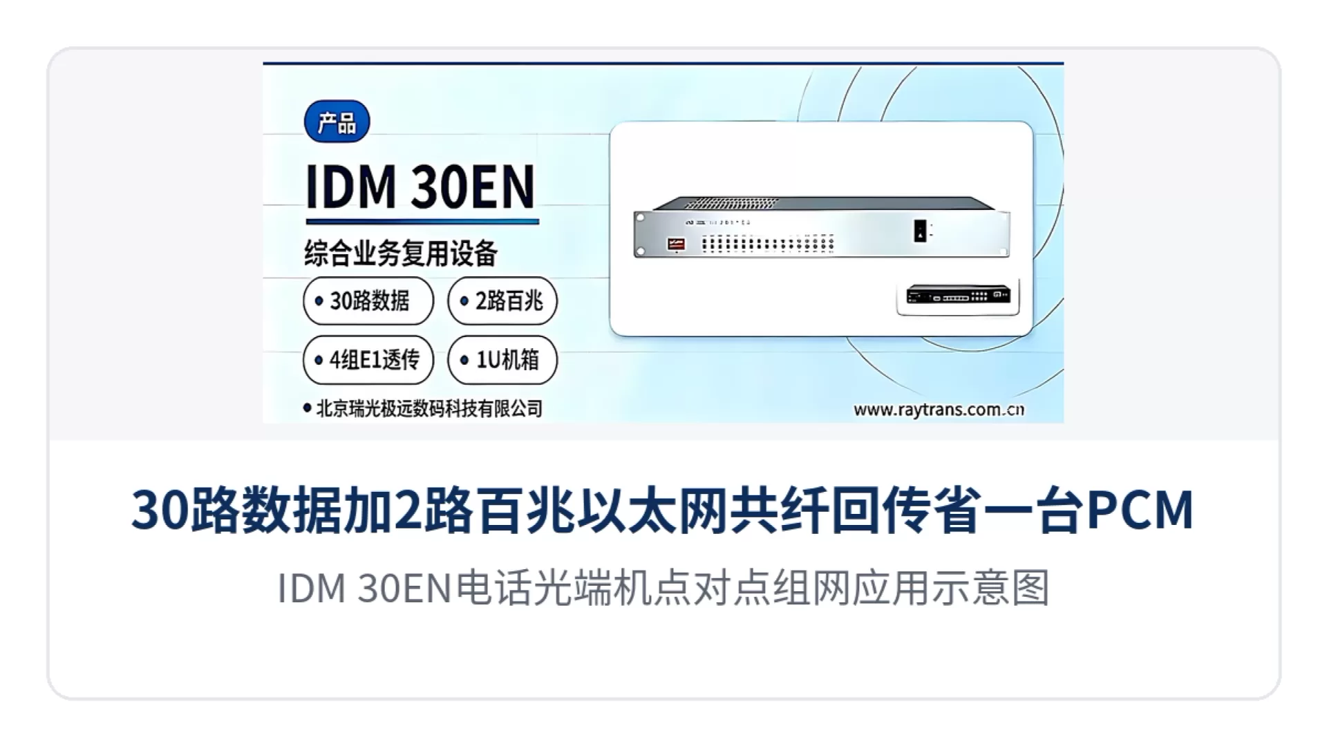
Figure 4: Point-to-point networking application diagram of the IDM-30EN telephone optical multiplexer
Differentiated Value of the IDM-30EN: 30 Channels of Data and 2 Channels of Fast Ethernet over One Fiber
The value of the IDM-30EN in carrying capacity is that a single 1U device carries 30 channels of data and 2 channels of wire-speed 100M Ethernet over the same fiber, saving one PCM device. When narrowband services and Ethernet services are transmitted separately, the site usually has to provide one set of equipment for each type and occupy one optical fiber or one E1 link each; the IDM-30EN combines both types of services into one 19-inch 1U device and one optical fiber, reducing cabinet space, associated cables and commissioning workload at the same time.
The value of the IDM-30EN in link compatibility is that 4 groups of E1 interfaces support transparent transmission and are compatible with existing G.703 transmission channels, so no link replacement is needed for a private network upgrade. In transparent transmission mode the device forwards the E1 stream as it is, without changing the time slots or signaling content in it, and the spare E1 ports on the existing PCM and SDH/PDH links on site can be reused directly; the bit rate of 2048kbit/s±50ppm, the HDB3 line coding and the PCM30/32 frame structure all follow the ITU-T G.703 recommendation, so only the impedance and line coding at both ends need to be checked when interconnecting with existing links.
The value of the IDM-30EN in optical path margin is its receiver sensitivity better than -34dBm and its receive dynamic range of 34dBm, which keep long-distance weak optical links running stably. Optical path loss fluctuates with distance, the number of splices and the environment; a receiver sensitivity better than -34dBm means a correct decision can still be made when link attenuation approaches the critical value, while the 34dBm receive dynamic range covers both weak-signal and strong-signal conditions; together with the transmit optical power of -4 to -12 dBm, the optical path attenuation calculation can be completed before commissioning.
Summary
The IDM-30EN 30-channel data + 2-channel Fast Ethernet same-fiber backhaul device packs 30 channels of data service, 2 channels of wire-speed 100M Ethernet and 4 groups of E1 transparent transmission into one 19-inch 1U chassis, so a single device completes same-fiber backhaul of narrowband services and Ethernet services and saves one PCM device; the 4 groups of E1 transparent transmission are compatible with existing G.703 links, and the receiver sensitivity better than -34dBm and the receive dynamic range of 34dBm cover long-distance links with weak optical signals, making it suitable for access and upgrade projects in scenarios such as electric power private networks, public security and emergency communications, and banking and financial dedicated lines.
Item | Parameter/Specification | Description/Applicable Conditions |
|---|---|---|
E1 interface standard | Fully compliant with the ITU-T G.703 recommendation | Check against this specification when interconnecting with existing PCM base groups and E1 ports on SDH/PDH links |
E1 bit rate | 2048kbit/s±50ppm | 2.048Mbit/s base group rate, with a frequency deviation within ±50ppm |
E1 line coding | HDB3 | Keep consistent with the line coding configuration of the device at the opposite end |
E1 impedance | 75Ω (unbalanced interface)/120Ω (balanced interface) | An external impedance converter is required when using the 120Ω balanced interface |
E1 frame structure | PCM30/32 | 32 time slots per frame, of which 30 time slots carry services |
E1 signaling | Channel-associated signaling (CAS) | Channel-associated signaling mode, transmitted together with the voice channel time slots |
FXO/FXS impedance | Three-element complex impedance 200Ω+560Ω//0.1μF | AC and DC characteristics of the voice channel interface |
FXO/FXS audio range | 300 Hz to 3400 Hz | Voice channel bandwidth, which meets the voice frequency band requirements |
FXO/FXS compression | A-law in ITU G.711 | Voice encoding uses A-law at 64K |
FXO/FXS loop current | 25mA/channel | Power feeding loop current for each telephone set |
Ethernet interface rate | 10/100M half-duplex and full-duplex | Negotiated according to port capabilities when interconnecting with switches and routers |
Ethernet interface protocol | Compliant with the IEEE-802.3u standard | 100BASE-TX Fast Ethernet specification |
Ethernet interface type | RJ-45 | The port mode is 10/100Mbps adaptive mode |
Optical interface rate | 155Mbps±50ppm | Optical port line rate, corresponding to the 155M optical transmission platform |
Optical interface wavelength | 1310nm | Commonly used operating wavelength for single-mode fiber (SMF); identical at both ends of a paired device |
Optical interface transmit power | -4 to -12 dBm | Used together with the optical path attenuation calculation |
Optical interface receiver sensitivity | Better than -34dBm | Minimum optical power at which the receiver can make a correct decision |
Optical interface receive dynamic range | 34dBm | Adaptation range for weak-signal and strong-signal optical links, especially important for long-distance links |
Optical interface form | FC | Optical port connector type, used with FC pigtails or patch cords |
Power supply mode and overall power consumption | Not yet recorded in the knowledge base | The manufacturer's technical documentation and commercial confirmation shall prevail |
Enclosure specifications | 19-inch 1U standard chassis | Facilitates rack installation in an equipment room cabinet |
Operating environment (temperature, humidity) | Not yet recorded in the knowledge base | The manufacturer's technical documentation and commercial confirmation shall prevail |
How Does Same-Fiber Backhaul Save One PCM Device?
Same-fiber backhaul saves one PCM device by merging narrowband services and Ethernet services onto the same integrated service multiplexer and the same optical fiber, so that one set of transmission equipment is no longer provided for each of the two types of services. One IDM-30EN simultaneously carries 30 channels of data service and 2 channels of wire-speed 100M Ethernet, and a single 19-inch 1U device completes the edge access coverage that previously required two types of equipment, a PCM device plus an Ethernet channel.
What is saved first is equipment and cabinet space. When narrowband services and Ethernet services are transmitted separately, the site usually has to provide one PCM device for the 30 channels of 64K service and arrange a separate channel for service system backhaul; the IDM-30EN packs both types of services into one 1U chassis that allows cabinet-to-cabinet installation alongside existing transmission equipment, reducing cabinet space usage and associated cables at the same time.
What is also saved is one optical fiber and one commissioning pass. The IDM-30EN brings 30 channels of data service and 2 channels of Fast Ethernet back to the central equipment room over a single optical fiber in one pass; at commissioning, only the E1 line coding and impedance at both ends need to be checked, optical port termination completed and the received optical power confirmed, and the on-site workload falls as the number of devices decreases.
Figure 3: Actual installation view of the IDM-30EN rack-mounted as a 1U unit in an equipment room cabinet
How Does E1 Transparent Transmission Interface with Existing G.703 Links?
E1 transparent transmission interfaces with existing G.703 links by having the 4 groups of E1 interfaces of the IDM-30EN multiplex the existing E1 channels on site in transparent transmission mode: the device forwards the incoming 2.048Mbit/s stream to the opposite end as it is, without parsing or changing the time slots and signaling content in it, so neither the existing link nor the transmission equipment at either end has to be replaced.
Before interfacing, check three specifications: the line coding is unified as HDB3, the frame structure is unified as the PCM30/32 format, and the impedance is unified as a 75Ω unbalanced interface or a 120Ω balanced interface (an external impedance converter is required when the 120Ω interface is used); the bit rate of 2048kbit/s±50ppm and the signaling mode follow the ITU-T G.703 recommendation, with channel-associated signaling transmitted together with the voice channel time slots.
After interfacing, set the clock mode according to the networking requirements on site: in different networking environments such as point-to-point and chain network, the master clock or the user clock can be set separately to avoid a conflict in the synchronization direction at the two ends. The 4 groups of E1 interfaces correspond one-to-one to the spare E1 ports on the existing link, so during a private network upgrade the configuration only has to match the existing number of channels.
How Does Receiver Sensitivity Affect Link Distance?
Receiver sensitivity has a direct effect on link distance: it determines how much link attenuation the receiver can tolerate and still make a correct decision; the lower the sensitivity value, the greater the permitted optical path attenuation and the longer the usable transmission distance. The receiver sensitivity of the IDM-30EN is better than -34dBm with a receive dynamic range of 34dBm, giving a wider adaptation range for both weak-signal and strong-signal optical links.
In an optical path budget calculation, the transmit optical power of the IDM-30EN is -4 to -12 dBm, which together with the receiver sensitivity better than -34dBm allows a link attenuation of about 22 dB; the actual transmission distance has to be calculated section by section in combination with the attenuation per kilometer of the optical cable, splice point loss and connector loss, and margin should especially be left for long-distance links.
For optical port interfacing, select pigtails or patch cords according to the rate of 155Mbps±50ppm, the wavelength of 1310nm and the FC interface form, keeping the wavelength identical at both ends of a paired device; in engineering practice it is recommended to check the received optical power with an optical power meter before commissioning and to judge whether the link is usable by comparing the actual measurement with the receiver sensitivity specification of the IDM-30EN.
Typical Application Scenarios of the IDM-30EN
Electric Power Private Network: Service Access at Substations and Power Supply Business Halls
Electric power private networks require stable links and simple operation and maintenance. Sites such as substations and power supply business halls usually have both narrowband services such as dispatch telephones and telecontrol data, and also need an Ethernet channel to backhaul service system data. The 30 channels of data service of the IDM-30EN can carry such 64K channels in a concentrated manner, the 2 channels of wire-speed 100M Ethernet meet office and service system backhaul needs, and the 4 groups of E1 interface transparent transmission can reuse the existing G.703 channels on site, so no existing transmission equipment has to be replaced during a link upgrade.
Public Security and Emergency Communications: Bringing Voice and Data Back to the Command Center over One Optical Fiber
Public security and emergency projects have scattered sites and long link distances, and the site often provides only a single optical fiber or one E1 link. The IDM-30EN brings 30 channels of data service and 2 Fast Ethernet channels back to the center over one optical fiber in one pass; with receiver sensitivity better than -34dBm and a receive dynamic range of 34dBm, it handles long-distance links with high optical cable attenuation, and after the device is rack-mounted, commissioning and fault location can be completed through the function control switches and alarm indication on the panel, reducing on-site maintenance trips.
Banking and Financial Dedicated Lines: Same-Fiber Transmission of Telephone and Service Data at Business Outlets
Banking and financial dedicated line scenarios are sensitive to line resources, and business outlets often need to provision telephone services and service data channels at the same time. The IDM-30EN places 30 channels of data service and 2 channels of wire-speed 100M Ethernet in one 19-inch 1U device; the network ports support VLAN partitioning, so different services can be divided into different VLANs for transmission, making it easy to distinguish service flows within one optical fiber channel; the 64K subscriber interfaces provide ordinary telephone cards (FXO, FXS) with caller ID (CID), and the telephones at a business outlet can be configured according to the on-site traffic.
Figure 4: Point-to-point networking application diagram of the IDM-30EN telephone optical multiplexer
Differentiated Value of the IDM-30EN: 30 Channels of Data and 2 Channels of Fast Ethernet over One Fiber
The value of the IDM-30EN in carrying capacity is that a single 1U device carries 30 channels of data and 2 channels of wire-speed 100M Ethernet over the same fiber, saving one PCM device. When narrowband services and Ethernet services are transmitted separately, the site usually has to provide one set of equipment for each type and occupy one optical fiber or one E1 link each; the IDM-30EN combines both types of services into one 19-inch 1U device and one optical fiber, reducing cabinet space, associated cables and commissioning workload at the same time.
The value of the IDM-30EN in link compatibility is that 4 groups of E1 interfaces support transparent transmission and are compatible with existing G.703 transmission channels, so no link replacement is needed for a private network upgrade. In transparent transmission mode the device forwards the E1 stream as it is, without changing the time slots or signaling content in it, and the spare E1 ports on the existing PCM and SDH/PDH links on site can be reused directly; the bit rate of 2048kbit/s±50ppm, the HDB3 line coding and the PCM30/32 frame structure all follow the ITU-T G.703 recommendation, so only the impedance and line coding at both ends need to be checked when interconnecting with existing links.
The value of the IDM-30EN in optical path margin is its receiver sensitivity better than -34dBm and its receive dynamic range of 34dBm, which keep long-distance weak optical links running stably. Optical path loss fluctuates with distance, the number of connectors and the environment; a receiver sensitivity better than -34dBm means a correct decision can still be made when link attenuation approaches the critical value, while the 34dBm receive dynamic range covers both weak-signal and strong-signal conditions; together with the transmit optical power of -4 to -12 dBm, the optical path attenuation calculation can be completed before commissioning.
Summary
The IDM-30EN 30-channel data + 2-channel Fast Ethernet same-fiber backhaul device packs 30 channels of data service, 2 channels of wire-speed 100M Ethernet and 4 groups of E1 transparent transmission into one 19-inch 1U chassis, so a single device completes same-fiber backhaul of narrowband services and Ethernet services and saves one PCM device; the 4 groups of E1 transparent transmission are compatible with existing G.703 links, and the receiver sensitivity better than -34dBm and the receive dynamic range of 34dBm cover long-distance links with weak optical signals, making it suitable for access and upgrade projects in scenarios such as electric power private networks, public security and emergency communications, and banking and financial dedicated lines.
FAQs
What is the working principle of Pulse Code Modulation (PCM)?
Working Principle Pulse Code Modulation is the process of converting a time-continuous…
View answerPCM30 Working Principle: What Is PCM30/32
PCM30 Equipment Working Principle The 30-channel PCM equipment refers to equipment that provides 30 user interfaces and…
View answerWhat are the common problems of PCM equipment in enterprise applications?
At present, PCM equipment has become basically ubiquitous in enterprise network applications.
View answerWhat is E1? How to Use E1
What is E1 The European 30-channel pulse code modulation PCM is abbreviated as E1, with a rate of 2.048Mbit/s.
View answerFrame Structure of 30/32-Channel PCM Primary Group
A communication system consists of transmitting equipment, receiving equipment, and transmission equipment.
View answer