
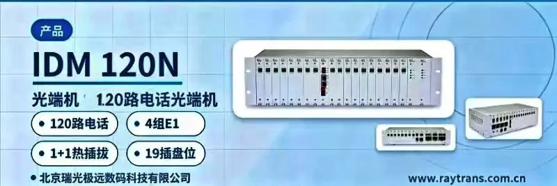
IDM-120N Telephone Optical Multiplexer
120 telephone channels plus 4 groups of E1 and 2 Fast Ethernet channels over the same fiber, eliminating multiple stacked devices
The IDM-120N multi-service optical multiplexer is PCM integrated service optical fiber transmission equipment designed by our company with dedicated large-scale integrated circuits. Its total bandwidth over the optical fiber is 155M, and it provides 2 shared line-rate 100M Ethernet interfaces, 4 groups of E1 transparent transmission interfaces and 120 telephone subscriber channels. The E1 transmission channels comply with the G.703 standard and adopt the PCM30/31 format; FXO and FXS can provide polarity reversal and caller ID functions. The device also provides dual backup and hot swapping of the power card and the ringing current card, greatly ensuring the reliability of service transmission. IDM-12
What Is the IDM-120N PCM Telephone Optical Multiplexer?
The IDM-120N PCM telephone optical multiplexer is PCM integrated service optical fiber transmission equipment designed by Beijing Ruiguang Jiyuan Digital Technology Co., Ltd. with dedicated large-scale integrated circuits, and it is used to simultaneously carry 120 telephone channels, 4 groups of transparent E1 transmission and 2 shared line-rate Fast Ethernet services over a single optical fiber link with 155M bandwidth. As a typical multi-service optical multiplexer, the device organizes narrowband voice channels and E1 channels according to the PCM30/31 format, its E1 transmission channels comply with the ITU-T G.703 standard, and the FXO and FXS interfaces support polarity reversal and caller ID; the power card and the power and ringing current card are configured in 1+1 redundancy and support hot swapping, and the complete unit is a 19-inch 3U chassis with a 19-card-slot structure. It can be widely used in public telephone network services of telecommunications and Netcom as well as leased-line information and data services for electric power, banking, public security and the military, and it is also a common access device in government private network optical fiber communication solutions and military emergency communications vehicle solutions.
Key specifications at a glance: 120 telephone channels · 4 groups of E1 · 2 shared line-rate Fast Ethernet · 155M optical fiber transmission bandwidth · 1+1 hot-swappable dual backup of the power card and the ringing current card · 19 card slots
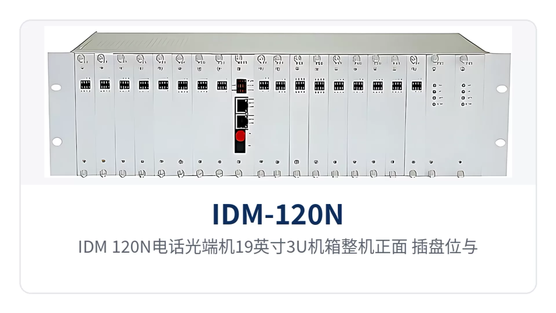
Figure 1: Front view, card slots and alarm indicator LEDs of the complete IDM-120N telephone optical multiplexer in a 19-inch 3U chassis
The IDM-120N telephone optical multiplexer uses a card-based structure, in which the 120 telephone voice channels are inserted as service cards and the chassis reserves multi-function card slots, so that it can be flexibly expanded as services grow and supports any network topology. The front panel provides function control switches and alarm indication, and together with the online network management function it enables online real-time configuration, query and fault statistics management of the device.
Knowledge Block: How the PCM30/31 Format Fits 120 Telephone Channels into 4 Groups of E1
The PCM30/31 format is the way the E1 primary group voice channels are organized. The IDM-120N telephone optical multiplexer encodes analog telephones into 64 kbit/s digital voice according to this format and places them into the E1 channels for transmission: each voice channel uses ITU-T G.711 A-law compression, with an audio range of 300 Hz to 3400 Hz and a loop current of 25 mA per channel, meeting the voice quality requirements of the public switched telephone network (PSTN). The E1 channels use a bit rate of 2048 kbit/s, HDB3 line coding and channel-associated signaling (CAS), and the 4 groups of E1 together provide 120 telephone subscriber channels; the three types of services, telephony, E1 and Ethernet, are transmitted over the same optical fiber link and are independent of each other.
What Functions and Interfaces Does the IDM-120N Telephone Optical Multiplexer Provide?
The IDM-120N PCM telephone optical multiplexer provides the following functions for high-capacity voice channel aggregation and multi-service optical fiber transmission.
Function | Description |
|---|---|
Aggregation of 120 telephone voice channels | A single device provides 120 telephone subscriber channels, and both the FXO and FXS interfaces support polarity reversal and caller ID, wired according to the exchange side or the user telephone side |
4 groups of transparent E1 transmission interfaces | Provides 4 groups of E1 channels with a bit rate of 2048 kbit/s and HDB3 line coding, compliant with ITU-T G.703, with 75 Ω/120 Ω selectable impedance and transparent transmission of channel-associated signaling (CAS) |
2 shared line-rate Fast Ethernet channels | Provides 2 RJ-45 Ethernet interfaces at 10/100Base-T and 10M/100M rates, compliant with IEEE802.3, adaptive half-duplex/full-duplex, sharing a line-rate 100M bandwidth |
16 subscriber interface slots | The 19-inch 3U chassis provides 16 subscriber interface slots, and 8-channel FXO/FXS service cards are inserted according to the voice channel direction, with the voice channel capacity configured by combining service cards |
Dual backup and hot-swappable power card and ringing current card | The power card PRU-120 and the power and ringing current card RPRU-120 are each configured in 1+1 redundancy and support hot-swappable replacement during operation, so that services are not interrupted in the power supply and ringing stages |
Expansion with multi-function card slots | Multi-function card slots are reserved for flexible expansion as services grow, supporting chain, star and other network topologies |
Function control switches and alarm indication | The front panel provides function control switches and alarm indication functions, facilitating on-site commissioning and fault location |
Online network management function | Supports online real-time configuration, query and fault statistics management through network management, and together with the alarm indication enables centralized maintenance |
How One Device Replaces Multiple Stacked Devices: 120 Telephone Channels, 4 Groups of E1 and 2 Fast Ethernet Channels over the Same Fiber
The core value of the IDM-120N PCM telephone optical multiplexer is that it aggregates into one 3U device the three types of services that previously needed multiple stacked devices. A conventional private network site usually uses one telephone optical multiplexer for subscriber line provisioning, one PDH optical multiplexer to transmit E1 and one more Ethernet optical multiplexer to backhaul data, occupying multiple rack positions and multiple pairs of optical fibers; the IDM-120N telephone optical multiplexer uses a total bandwidth of 155M over the optical fiber to carry 120 telephone channels, 4 groups of E1 and 2 shared line-rate Fast Ethernet in a unified way, so the site side needs only one device and a pair of optical fibers, and the occupation of rack positions and optical fiber resources is reduced accordingly.
At the service level, the three types of services, telephony, E1 and Ethernet, do not interfere with one another: the E1 channels are transmitted transparently according to ITU-T G.703 and can interface with existing PCM and SDH equipment, the Ethernet interfaces comply with IEEE802.3 and can be directly connected to IP devices such as switches and routers, and the 120 voice channels are configured with 8 channels per card according to the FXO/FXS direction, with service cards simply added or removed according to the actual number of voice channels in the project.
Card Composition of the Complete Unit and Capacity Expansion
A single IDM-120N telephone optical multiplexer consists of the chassis backplane, the main control card, the power card (power and ringing current card) and the FXO/FXS service cards, and the models and functions of each card are as follows.
Card slot | Name | Model | Description | Quantity |
|---|---|---|---|---|
1 | Equipment chassis backplane | IDM-120 | 19-inch 3U chassis, providing 19 card slots | 1 |
2 | E1 interface main control card | CMU-E1-120 | Provides E1 interface access | 1 |
3 | Optical interface main control card | CMU-120 | Provides 1 optical interface access, 2 line-rate 100M Ethernet interfaces and 4 E1 interfaces | 1 |
4 | Power card | PRU-120 | Provides 1+1 power supply and power for the complete unit, used on the FXO side, -48V input | 2 |
5 | Power and ringing current card | RPRU-120 | Provides 1+1 power supply, power for the complete unit and ringing voltage, used on the FXS side, -48V input | 2 |
6 | FXO service card | 8FXO-120 | 8 FXO interfaces, exchange side | As required |
7 | FXS service card | 8FXS-120 | 8 FXS interfaces, user side | As required |
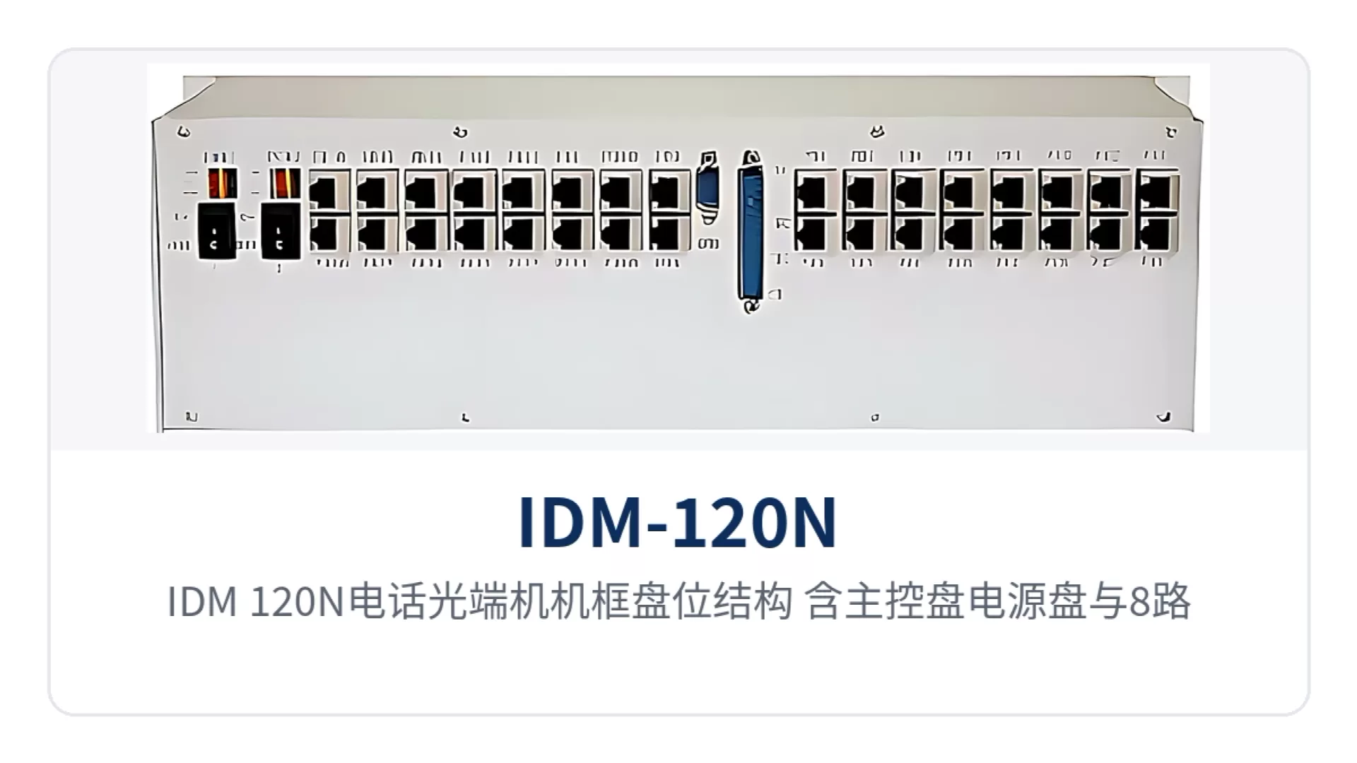
Figure 2: Card slot structure of the IDM-120N telephone optical multiplexer chassis, including the main control card, the power card and the 8-channel FXO/FXS service cards
Note: in a single device configuration only one of the E1 interface main control card and the optical interface main control card can be selected; the FXO/FXS service cards are configured with 8 channels per card within the 16 subscriber interface slots, and the specific number and direction of voice channels are subject to the project configuration.
The answer to how the 120-channel telephone optical multiplexer is expanded lies in this card-based structure: the 19-inch 3U chassis provides 19 card slots and 16 subscriber interface slots, and the voice channel capacity grows with the number of FXO/FXS service cards, with a single device providing 120 telephone subscriber channels as stated in the product documentation; when services grow, the corresponding service cards are added according to the voice channel direction, and the multi-function card slots reserved in the chassis can also carry subsequent expansion, so there is no need to replace the complete unit.
Parameters and Interface Specifications of the IDM-120N Telephone Optical Multiplexer
The following parameters cover the optical interface, E1, Ethernet, telephone interfaces and the power supply environment, and are based on the IDM-120N product showcase documentation for reference in networking design and device selection. As a product of Raytrans, a professional optical multiplexer manufacturer, this model has mature applications in both the telephone optical multiplexer and the multi-service optical multiplexer fields.
Optical Interface Parameters
Item | Parameter/Specification | Description |
|---|---|---|
Interface type | FC (can be customized to SC, etc.) | Selected according to the on-site optical fiber connector |
Fiber mode | Single-mode (multi-mode optional) | Single-mode is used for longer-distance transmission |
Optical fiber rate | 155 bit/s±50ppm | Corresponds to the 155M optical fiber transmission bandwidth of the complete unit |
Wavelength | 1310nm | Single-mode fiber (SMF) transmission window |
Transmit optical power | -2 to -11 dBm | Transmit optical power range |
Receiver sensitivity | Better than -36 dBm | Optical reception performance indicator; the actual transmission distance is calculated according to the optical power budget |
E1 Interface Parameters
Item | Parameter/Specification | Description |
|---|---|---|
Bit rate | 2048 kbit/s | Standard rate of an E1 line |
Line coding | HDB3 | Meets the ITU-T G.703 line coding requirements |
Standard protocol | ITU-T G.703 | E1 electrical interface standard |
Impedance | 75 Ω/120 Ω | Coaxial or balanced interface selectable |
Frame structure | PCM30/31 | Voice channels are organized according to the PCM30/31 format |
Signaling | Channel-associated signaling (CAS) | A commonly used signaling mode for interfacing with stored program control (SPC) switching offices |
Ethernet Interface Parameters
Item | Parameter/Specification | Description |
|---|---|---|
Interface type | RJ-45 | Ethernet electrical interface |
Transmission rate | 10/100Base-T, 10M/100M | Rate adaptive |
Standard protocol | IEEE802.3 | Ethernet standard protocol |
Operating mode | Adaptive half-duplex/full-duplex | Can be directly connected to Ethernet devices such as switches |
FXO/FXS Telephone Interface Parameters
Item | Parameter/Specification | Description |
|---|---|---|
Audio range | 300 Hz to 3400 Hz | Telephone voice band |
Impedance | Three-element complex impedance 200 Ω+560 Ω//0.1 μF | Return loss characteristics of the telephone interface |
Compression | ITU-T G.711 A-law | Voice encoding method |
Loop current | 25 mA per channel | Powered from the telephone central office |
Additional functions | Polarity reversal, caller ID | Supported by both the FXO and FXS interfaces |
Power Supply, Environment and Chassis
Item | Parameter/Specification | Description |
|---|---|---|
Power supply mode | DC-48V or AC 220V | Selected according to the power supply conditions of the equipment room or the site |
Overall power consumption | ≤250W | Upper limit of the overall power consumption |
Operating temperature | 0 °C to +40 °C | Suitable for indoor equipment room environments |
Humidity | 95% non-condensing | Relative humidity requirement |
Product dimensions | Length×Depth×Height 480×200×132 mm | Installation dimensions of the 19-inch 3U chassis |
Typical Application Scenarios: Electric Power, Military and Public Security, and Banking Leased Lines
The IDM-120N PCM telephone optical multiplexer can be widely used in public telephone network services of telecommunications and Netcom as well as leased-line information and data services for electric power, banking, public security and the military, and the following are three typical uses. As a multi-service optical multiplexer introduced by Raytrans, the device is also suitable for scenarios such as government private network optical fiber communication solutions and military emergency communications vehicle solutions.
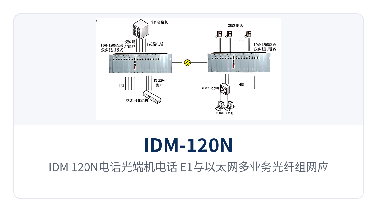
Figure 3: Networking diagram of the IDM-120N telephone optical multiplexer for multi-service optical fiber application of telephony, E1 and Ethernet
Electric Power Private Network: Telephone and Data Services over the Same Fiber at Substations
Electric power private network sites usually need to enable dispatching and office telephones at the same time and to connect E1 leased-line channels that carry service data. After the IDM-120N telephone optical multiplexer is deployed at substations, power supply stations and similar sites, subscriber line provisioning for telephone services is performed through the FXO/FXS interfaces, the E1 channels carry leased-line data through ITU-T G.703 transparent transmission, and the 2 Fast Ethernet interfaces backhaul IP services, so all access is completed over a pair of optical fibers without providing a separate transmission device for telephones and data.
Military and Public Security Private Networks: Highly Reliable Voice and Leased-Line Data Transmission
Military and public security private networks have high requirements for voice quality and link reliability, and their sites are often unattended. The IDM-120N PCM telephone optical multiplexer carries 120 voice channels together with E1 and Ethernet services over a 155M optical fiber bandwidth, voice uses ITU-T G.711 A-law encoding, and E1 complies with ITU-T G.703 and the PCM30/31 format so that it enables intercommunication with existing private network transmission equipment; the 1+1 dual backup of the power card and the power and ringing current card supports hot swapping, so a single card failure can be handled during operation, and the online network management allows the operating status of each site to be monitored remotely, reducing on-site inspection workload. In military emergency communications vehicle solutions, this optical multiplexer can likewise take advantage of rapid deployment and multi-service convergence.
Banking Leased Lines: Centralized Backhaul of Telephone and Data Services from Business Outlets
Banks have many widely distributed business outlets, and the outlet side needs subscriber line provisioning and leased-line data backhaul while ensuring availability. At the outlet side, the IDM-120N telephone optical multiplexer connects telephones through the FXS interfaces and connects switching and data side equipment through the FXO interfaces or E1 channels, the Ethernet interfaces carry outlet IP services, and the voice channels and data of multiple business outlets are backhauled to the upper-level node in a centralized way; AC 220V or DC -48V power supply can be selected according to the equipment room conditions, and the 19-inch 3U chassis is suitable for installation in a standard cabinet.
Selection and Deployment Recommendations
The IDM-120N PCM telephone optical multiplexer is suitable for private network nodes that need high-capacity subscriber line provisioning together with E1 and Ethernet services. During selection, determine the number of FXO/FXS service cards according to the voice channel direction, select the FC (can be customized to SC, etc.) optical interface and single-mode (multi-mode optional) optical fiber according to the optical fiber resources, and choose DC-48V or AC 220V according to the on-site power supply conditions; the unit's operating temperature is 0 °C to +40 °C with 95% non-condensing humidity, and it is recommended to deploy it in an indoor equipment room environment. For sites with high reliability requirements, the 1+1 hot-swappable dual backup design of the power card and the power and ringing current card can be used together with online network management to achieve centralized maintenance of configuration, query and fault statistics, and for specific configuration plans it is recommended to confirm with optical multiplexer manufacturers such as Raytrans according to the project requirements.
Card slot | Name | Model | Description | Quantity |
|---|---|---|---|---|
1 | Equipment chassis backplane | IDM-120 | 19-inch 3U chassis, providing 19 card slots | 1 |
2 | E1 interface main control card | CMU-E1-120 | Provides E1 interface access | 1 |
3 | Optical interface main control card | CMU-120 | Provides 1 optical interface access, 2 line-rate 100M Ethernet interfaces and 4 E1 interfaces | 1 |
4 | Power card | PRU-120 | Provides 1+1 power supply and power for the complete unit, used on the FXO side, -48V input | 2 |
5 | Power and ringing current card | RPRU-120 | Provides 1+1 power supply, power for the complete unit and ringing voltage, used on the FXS side, -48V input | 2 |
6 | FXO service card | 8FXO-120 | 8 FXO interfaces, exchange side | As required |
7 | FXS service card | 8FXS-120 | 8 FXS interfaces, user side | As required |
Figure 2: Card slot structure of the IDM-120N telephone optical multiplexer chassis, including the main control card, the power card and the 8-channel FXO/FXS service cards
Note: in a single device configuration only one of the E1 interface main control card and the optical interface main control card can be selected; the FXO/FXS service cards are configured with 8 channels per card within the 16 subscriber interface slots, and the specific number and direction of voice channels are subject to the project configuration.
The answer to how the 120-channel telephone optical multiplexer is expanded lies in this card-based structure: the 19-inch 3U chassis provides 19 card slots and 16 subscriber interface slots, and the voice channel capacity grows with the number of FXO/FXS service cards, with a single device providing 120 telephone subscriber channels as stated in the product documentation; when services grow, the corresponding service cards are added according to the voice channel direction, and the multi-function card slots reserved in the chassis can also carry subsequent expansion, so there is no need to replace the complete unit.
Parameters and Interface Specifications of the IDM-120N Telephone Optical Multiplexer
The following parameters cover the optical interface, E1, Ethernet, telephone interfaces and the power supply environment, and are based on the IDM-120N product showcase documentation for reference in networking design and device selection. As a product of Raytrans, a professional optical multiplexer manufacturer, this model has mature applications in both the telephone optical multiplexer and the multi-service optical multiplexer fields.
Optical Interface Parameters
Item | Parameter/Specification | Description |
|---|---|---|
Interface type | FC (can be customized to SC, etc.) | Selected according to the on-site optical fiber connector |
Fiber mode | Single-mode (multi-mode optional) | Single-mode is used for longer-distance transmission |
Optical fiber rate | 155 bit/s±50ppm | Corresponds to the 155M optical fiber transmission bandwidth of the complete unit |
Wavelength | 1310nm | Single-mode fiber (SMF) transmission window |
Transmit optical power | -2 to -11 dBm | Transmit optical power range |
Receiver sensitivity | Better than -36 dBm | Optical reception performance indicator; the actual transmission distance is calculated according to the optical power budget |
E1 Interface Parameters
Item | Parameter/Specification | Description |
|---|---|---|
Bit rate | 2048 kbit/s | Standard E1 bit rate |
Line coding | HDB3 | Meets the ITU-T G.703 line coding requirements |
Standard protocol | ITU-T G.703 | E1 electrical interface standard |
Impedance | 75 Ω/120 Ω | Coaxial or balanced interface selectable |
Frame structure | PCM30/31 | Voice channels are organized according to the PCM30/31 format |
Signaling | Channel-associated signaling (CAS) | A commonly used signaling mode for interfacing with stored program control (SPC) switching offices |
Ethernet Interface Parameters
Item | Parameter/Specification | Description |
|---|---|---|
Interface type | RJ-45 | Ethernet electrical interface |
Transmission rate | 10/100Base-T, 10M/100M | Rate adaptive |
Standard protocol | IEEE802.3 | Ethernet standard protocol |
Operating mode | Adaptive half-duplex/full-duplex | Can be directly connected to Ethernet devices such as switches |
FXO/FXS Telephone Interface Parameters
Item | Parameter/Specification | Description |
|---|---|---|
Audio range | 300 Hz to 3400 Hz | Telephone voice band |
Impedance | Three-element complex impedance 200 Ω+560 Ω//0.1 μF | Return loss characteristics of the telephone interface |
Compression | ITU-T G.711 A-law | Voice encoding method |
Loop current | 25 mA per channel | Feeding capability for the telephone set |
Additional functions | Polarity reversal, caller ID | Supported by both the FXO and FXS interfaces |
Power Supply, Environment and Chassis
Item | Parameter/Specification | Description |
|---|---|---|
Power supply mode | DC-48V or AC 220V | Selected according to the power supply conditions of the equipment room or the site |
Overall power consumption | ≤250W | Upper limit of the overall power consumption |
Operating temperature | 0 °C to +40 °C | Suitable for indoor equipment room environments |
Humidity | 95% non-condensing | Relative humidity requirement |
Product dimensions | Length×Depth×Height 480×200×132 mm | Installation dimensions of the 19-inch 3U chassis |
Typical Application Scenarios: Electric Power, Military and Public Security, and Banking Leased Lines
The IDM-120N PCM telephone optical multiplexer can be widely used in public telephone network services of telecommunications and Netcom as well as leased-line information and data services for electric power, banking, public security and the military, and the following are three typical uses. As a multi-service optical multiplexer introduced by Raytrans, the device is also suitable for scenarios such as government private network optical fiber communication solutions and military emergency communications vehicle solutions.
Figure 3: Networking diagram of the IDM-120N telephone optical multiplexer for multi-service optical fiber application of telephony, E1 and Ethernet
Electric Power Private Network: Telephone and Data Services over the Same Fiber at Substations
Electric power private network sites usually need to enable dispatching and office telephones at the same time and to connect E1 leased-line channels that carry service data. After the IDM-120N telephone optical multiplexer is deployed at substations, power supply stations and similar sites, subscriber line provisioning for telephone services is performed through the FXO/FXS interfaces, the E1 channels carry leased-line data through ITU-T G.703 transparent transmission, and the 2 Fast Ethernet interfaces backhaul IP services, so all access is completed over a pair of optical fibers without providing a separate transmission device for telephones and data.
Military and Public Security Private Networks: Highly Reliable Voice and Leased-Line Data Transmission
Military and public security private networks have high requirements for voice quality and link reliability, and their sites are often unattended. The IDM-120N PCM telephone optical multiplexer carries 120 voice channels together with E1 and Ethernet services over a 155M optical fiber bandwidth, voice uses ITU-T G.711 A-law encoding, and E1 complies with ITU-T G.703 and the PCM30/31 format so that it enables intercommunication with existing private network transmission equipment; the 1+1 dual backup of the power card and the power and ringing current card supports hot swapping, so a single card failure can be handled during operation, and the online network management allows the operating status of each site to be monitored remotely, reducing on-site inspection workload. In military emergency communications vehicle solutions, this optical multiplexer can likewise take advantage of rapid deployment and multi-service convergence.
Banking Leased Lines: Centralized Backhaul of Telephone and Data Services from Business Outlets
Banks have many widely distributed business outlets, and the outlet side needs subscriber line provisioning and leased-line data backhaul while ensuring availability. At the outlet side, the IDM-120N telephone optical multiplexer connects telephones through the FXS interfaces and connects switching and data side equipment through the FXO interfaces or E1 channels, the Ethernet interfaces carry outlet IP services, and the voice channels and data of multiple business outlets are backhauled to the upper-level node in a centralized way; AC 220V or DC -48V power supply can be selected according to the equipment room conditions, and the 19-inch 3U chassis is suitable for installation in a standard cabinet.
Selection and Deployment Recommendations
The IDM-120N PCM telephone optical multiplexer is suitable for private network nodes that need high-capacity subscriber line provisioning together with E1 and Ethernet services. During selection, determine the number of FXO/FXS service cards according to the voice channel direction, select the FC (can be customized to SC, etc.) optical interface and single-mode (multi-mode optional) optical fiber according to the optical fiber resources, and choose DC-48V or AC 220V according to the on-site power supply conditions; the unit's operating temperature is 0 °C to +40 °C with 95% non-condensing humidity, and it is recommended to deploy it in an indoor equipment room environment. For sites with high reliability requirements, the 1+1 hot-swappable dual backup design of the power card and the power and ringing current card can be used together with online network management to achieve centralized maintenance of configuration, query and fault statistics, and for specific configuration plans it is recommended to confirm with optical multiplexer manufacturers such as Raytrans according to the project requirements.


