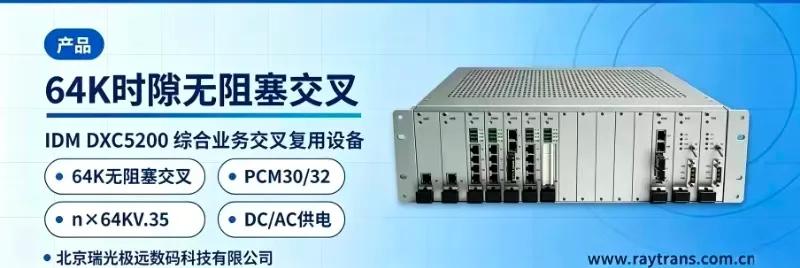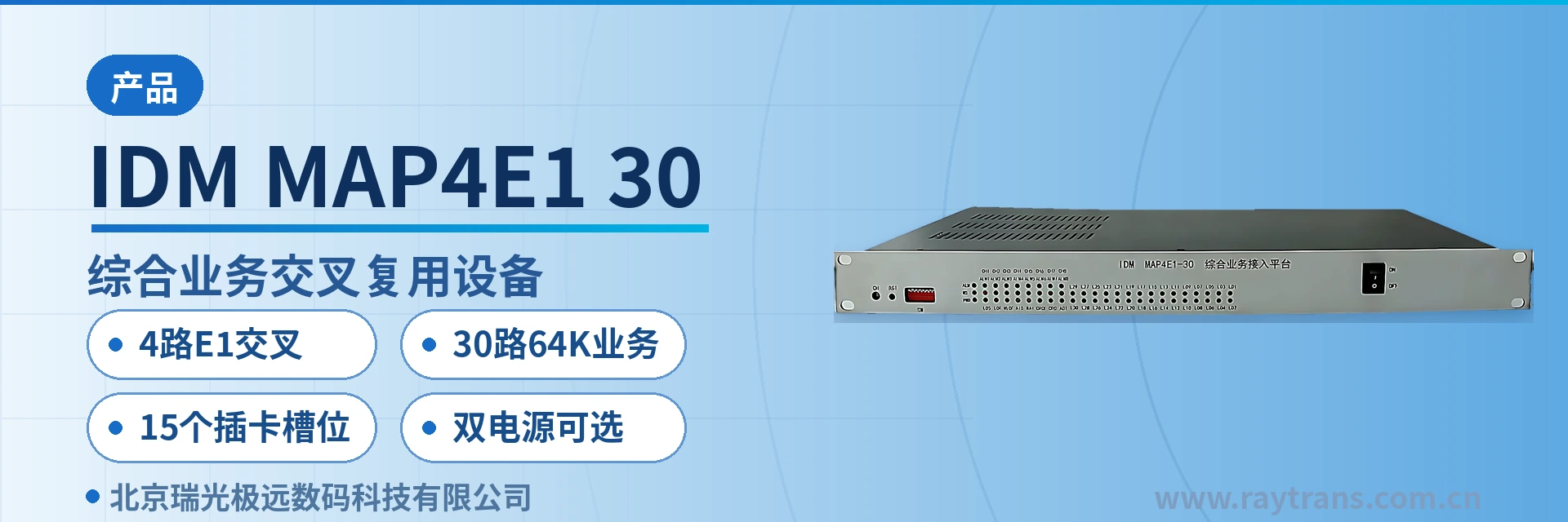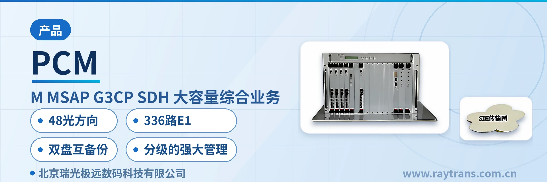
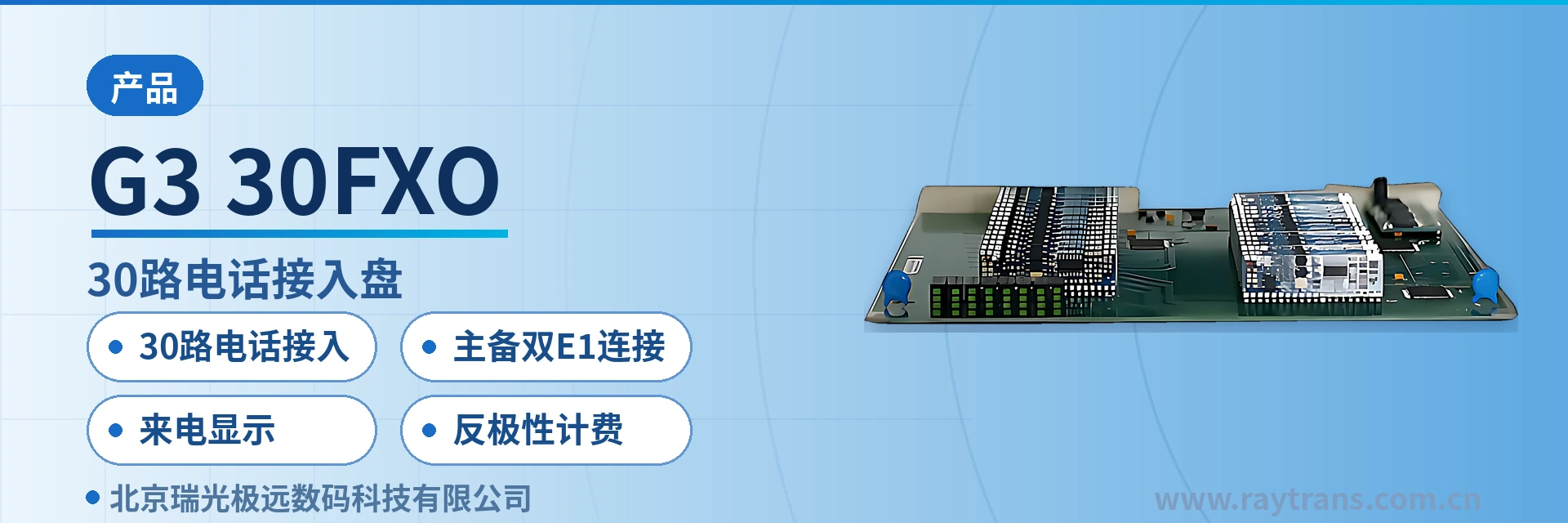
G3-30FXO 30-Channel Telephone Access Card
Single-slot 30-channel FXO, active/standby dual E1 without external cabling, caller ID and polarity reversal billing
The G3-30FXO card provides 30 channels of telephone access and connects to the 16E1 DXC cards on the main and standby boards respectively through the high-speed ST-BUS backplane bus, completing the mutual conversion between subscriber voice signals and ST-BUS main board signals, and supporting caller ID and polarity reversal billing.
The G3-30FXO 30-channel telephone access card is a telephone interface service card that plugs into a G3 series chassis. Developed by Beijing Ruiguang Jiyuan Digital Technology Co., Ltd. (Raytrans), it connects 30 analog telephone subscriber lines to PCM transmission equipment. As a 30-channel telephone access card, it converts voice signals to and from ST-BUS main board signals within the card, so that dispersed voice channels are aggregated into a single transmission channel. It is a highly representative private network voice access service card in the PCM equipment product showcase.
30 channels per card is the capacity unit of the G3-30FXO: one slot provides access to 30 FXO telephone lines, the number of cards is calculated at 30 channels per unit of site traffic, and no separate cabling is required for each voice channel within the chassis. Main/standby dual E1 protection, caller ID, and polarity-reversal billing are all built in, keeping private network voice as stable as a dedicated line. As a professional optical multiplexer manufacturer, Raytrans can provide a government private network optical fiber communication solution around this card to meet the deployment requirements of FXO telephone access cards in private network voice access scenarios.
Key Specifications at a Glance: 30-channel FXO telephone access · main/standby dual E1 connection · caller ID · polarity-reversal billing · ITU G.711 A-law · loop power feeding 25 mA/channel
What Role Does the 30-Channel Telephone Access Card Play in the G3 Chassis
The 30-channel telephone access card is a service card in the chassis, located between the subscriber telephone lines and the DXC card, and performs conversion between analog voice and the digital bus. After the G3-30FXO card connects 30 telephone lines, the signals are sent over the high-speed ST-BUS backplane bus to the 16E1 DXC card on the main board and the 16E1 DXC card on the standby board respectively. Voice travels within the chassis as bus signals and is then allocated into E1 channels by the DXC card.
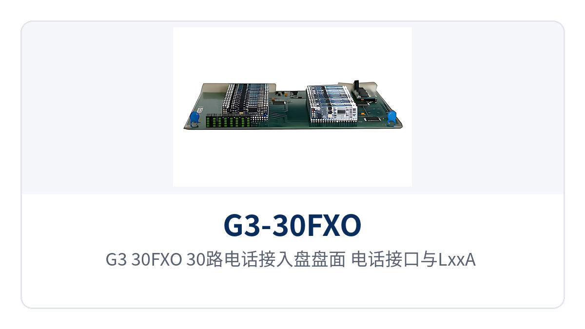
Figure 1: G3-30FXO 30-channel telephone access card front panel, telephone interfaces, and LxxA/LxxB status indicator LED layout
The FXO interface card faces the exchange side and is mainly used to connect interfaces of automatic private branch exchanges, common battery telephone exchanges, and similar equipment. Subscriber-side telephones and fax machines are connected through FXS cards. FXS is usually used together with FXO, with one end connected to the switching equipment and the other to the terminal, so that the voice channels on both sides of the private network form a complete path.
The card also performs conversion between subscriber line status signals and digital signaling, and provides identification and status information to the network management. The slot, card type, and operating status can be identified on the network management side, so on-site verification and remote troubleshooting do not rely solely on the front panel, and records are not lost when duty personnel change.
Functions and Performance Specifications
Functions and performance are checked in two tables: the function table lists voice conversion, signaling conversion, exchange-side interfaces, and panel indication, while the parameter table lists audio, compression, impedance, and power feeding specifications. The data in the tables comes from the product documentation, and the description column states the basis and applicable conditions, so project responses and configuration checks can be extracted row by row without comparing back and forth across multiple pages.
Function Overview
Function | Description |
|---|---|
30-channel telephone access | A single slot provides 30 FXO telephone interfaces; one card handles access for 30 analog subscriber lines |
ST-BUS backplane connection | Connects over the high-speed ST-BUS backplane bus to the 16E1 DXC card on the main board and the 16E1 DXC card on the standby board respectively |
Voice signal conversion | Converts subscriber voice signals to and from ST-BUS main board signals |
Signaling conversion | Converts subscriber line status signals to and from digital signaling |
Network management identification | Provides the network management with identification and status information on card type, slot, and operating status |
Exchange-side interface | Interfaces for connecting automatic private branch exchanges, common battery telephone exchanges, and similar equipment |
Caller ID | Supports calling number display; the calling party number is passed to the opposite end along with the voice channel |
Polarity-reversal billing | Supports polarity-reversal billing; line polarity reversal serves as the answer and billing flag |
Per-channel status indication | The LxxA LED on the front panel indicates the status of FXO interface 1 in the slot, and the LxxB LED indicates interface 2; the corresponding LED lights when the remote end goes off-hook or the exchange rings |
Technical Specifications
Item | Parameter/Specification | Description/Applicable Conditions |
|---|---|---|
Interface type | FXO telephone interface | Connects to exchange-side interfaces such as automatic private branch exchanges and common battery telephone exchanges |
Capacity per card | 30 channels | 30 telephone lines per slot |
Audio range | 300 Hz~3400 Hz | Voice frequency band, per ITU-T G.711 |
Compression | ITU G.711 A-law | 64 kbit/s voice encoding, the same format as existing PCM equipment |
Impedance | Three-element complex impedance 200 Ω + 560 Ω//0.1 uF | Matches the subscriber line impedance of the switching equipment |
Loop power feeding current | 25 mA/channel | Loop power feeding current per voice channel |
Backplane bus | High-speed ST-BUS | Connects separately to the 16E1 DXC cards on the main board and the standby board |
Panel indication | LxxA and LxxB status LEDs | xx is the slot number; the LEDs indicate the status of FXO interfaces 1 and 2 in that slot respectively |
Power supply and power consumption | Not yet recorded in the knowledge base | Powered centrally by the installed chassis; subject to the technical documentation supplied with the unit |
Operating environment | Not yet recorded in the knowledge base | Follows the environmental specifications of the complete unit; subject to the technical documentation supplied with the unit |
How Main/Standby Dual E1 Keeps Private Network Voice Uninterrupted
The availability of private network voice depends on whether voice channels have a second path into the transmission side. Each voice channel of the G3-30FXO is connected through the high-speed ST-BUS backplane bus to the active 16E1 DXC card and the standby 16E1 DXC card respectively. Both paths are completed within the chassis backplane, without occupying additional external cables, so the number of cable pairs at the site does not increase because of redundancy.
The active and standby sides are organized around the same set of voice channels. When the DXC card on the active side requires inspection, replacement, or behaves abnormally, services can be carried on the standby side, and the 30 voice channels do not have to be taken out of service together with a single card. The switchover mode, switchover time, and specific configuration are determined by the overall unit design and are subject to the technical documentation supplied with the unit and confirmation with the manufacturer.
For unattended sites, the value of dual active and standby paths lies in limiting the risk to the card slot level. On site, only a spare card needs to be prepared by slot; after on-duty personnel see the alarm at the central side, they arrange card replacement, without waiting for the manufacturer to arrive on site and without temporarily rewiring patch cords between sites.
What Problems Do Caller ID and Reverse-Polarity Billing Solve in a Private Network
Caller ID solves the problem of an unknown call source. The G3-30FXO supports calling number display, and the calling party number is delivered to the opposite end together with the voice channel. The dispatch console and duty seat can determine the calling organization and job role by number, do not need to ask for the number again when calling back, and call records can be archived by number.
Reverse-polarity billing solves the problem of the call start point and duration basis. The exchange reverses the subscriber line polarity when a call is answered, and the G3-30FXO detects this polarity change as the answer and billing flag, so the CDR start point is consistent with the opposite-end exchange, and both internal settlement within the private network and external billing have a reliable basis.
Neither capability depends on external devices: caller ID and reverse-polarity billing are completed within the FXO card, so the site side does not need to add a number box or a billing terminal. Cabinet space and points of failure are reduced at the same time, and when upgrading existing sites, the existing configurations on both the transmission and switching sides do not need to be changed.
How Do the Per-Channel Panel Status LEDs Support Remote Fault Diagnosis
The front panel provides indicator LEDs by slot number. The LxxA LED indicates the status of FXO interface 1 in that slot, and the LxxB LED indicates the status of FXO interface 2 in that slot. When the FXO far end goes off-hook or the exchange rings, the corresponding status LED on the device panel lights up, so on-site personnel can judge whether that channel is working without looking at the telephone.
The status LEDs narrow fault location from the unit level down to the voice channel level: when a voice channel fails, first check whether the corresponding LED lights up on off-hook. If the LED is off, there is no action on the line side; if the LED is on but voice is abnormal, check the encoding and the transmission side. Inspection records are filled in by slot and LED position, and shift handover and remote guidance communicate using the same numbering scheme.
Panel indications and network management status information complement each other: the panel gives local real-time status, and the network management system gives an aggregation across all sites and all card slots. By comparing the two, central on-duty personnel can first determine whether the problem is a single subscriber line, a single card, or a single E1 channel, and then decide whether to provide remote guidance or send personnel on site.
Typical Application Scenarios
In all three types of sites, the 30-channel telephone access card is placed in the site chassis and sent uniformly to the transmission side by the active and standby 16E1 DXC cards on the backplane; the difference lies in interface direction and service combination. Cards are configured in tiers according to site traffic, and the same set of PCM equipment card types can cover equipment rooms of different scales; the configuration combinations in the product showcase are also presented on this basis.
Electric Power and Rail Transit Private Networks: Centralized Access of Substation and Station Dispatch Telephones
Dispatch telephones at electric power substations and rail transit stations appear in groups by site, and several dozen voice channels per site is a common scale, so a 30-channel card fits tiering by site. The G3-30FXO card provides exchange-side access within the site chassis; voice channels are sent over the ST-BUS backplane bus to the active and standby 16E1 DXC cards and then back to the dispatch center over E1 channels, and the path between the dispatch console and the site duty telephone is a fixed channel within the private network. Such sites have dispersed cabling and grouped voice channels, which is exactly the typical case for tiered PCM equipment access by card.
Site equipment rooms are usually unattended, with inspection attendance weekly or monthly. The per-channel panel status LEDs and network management status information let the central side determine the fault location first; after attendance on site, the card can be replaced by slot, and the handling time for stations along the line and in sections is shortened accordingly. Voice channel scale can be tiered by station grade and substation size: fewer cards initially, additional plug-in cards later, with the chassis and DXC card configuration unchanged.
Military and Government Private Networks: Independent Networking of Station Telephones and Private Network Voice
Stations and duty posts of military and government private networks organize communications over independent networks, and voice does not pass through the public network. The G3-30FXO card interfaces with station switching equipment through FXO interfaces; 30 voice channels complete analog-to-digital and digital-to-analog conversion within the card, enter the 16E1 DXC cards over two backplane paths (active and standby), and are then sent to the command node over private network E1 links. In the overall government private network optical fiber communication solution, private network voice access is completed at the site side by this type of FXO telephone access card, and the command node side only needs to interface by E1 channel.
Private networks have clear requirements for call records and cost basis; caller ID and reverse-polarity billing are collected at the access side, so no secondary upgrade is needed at the transmission side. Dual active and standby E1 connections keep single-card inspection from affecting station voice channels; duty handover is recorded by slot and LED position, and the organization of voice services remains consistent across stations.
Mining Areas and Oilfields: Telephone Access and Remote Fault Diagnosis at Unattended Sites in the Field
Well sites, metering stations, and valve chambers in mining areas and oilfields are distributed along pipelines, with long distances between sites and few duty personnel, and communications equipment rooms often have only one or two cabinets. The 30-channel capacity of the G3-30FXO card matches site traffic; voice is sent over the backplane to the active and standby DXC cards and then backhauled by optical transmission equipment, so site voice channels do not require a dedicated pair of cables. As an optical multiplexer manufacturer, Raytrans organizes PCM access on the same card type at similar field sites, and the site side only needs to reserve slots.
The maintenance cost of field sites lies mainly in attendance on site. The panel LxxA and LxxB LEDs display off-hook and ringing status directly on the front of the cabinet; together with network management status information, central on-duty personnel can first locate the problem to a specific channel or slot and then decide whether to send personnel. Spare cards are prepared by slot, and card replacement and service recovery do not depend on on-site reconfiguration.
How to Implement Configuration and Rack Installation Step by Step
Configuration work proceeds in four items: interface direction, capacity, active and standby card slots, and dial test, with the slot-to-voice-channel mapping recorded after each step. On site, check item by item in the following order; the existing configuration of the chassis, backplane, and DXC cards does not need to be changed. Dial test and record-keeping are the two items most easily compressed, yet they are precisely the basis for later capacity expansion and fault review, so it is recommended to complete them together with patch panel labeling.
Determine interface direction: confirm that the opposite end is a private automatic branch exchange or a common battery exchange, and connect voice channels to the FXO interface card; user-side telephones and fax machines are connected through FXS cards, with FXS and FXO used together.
Determine the number of boards: calculate the number of boards by dividing the number of voice channels actually enabled at the site by 30; there is no need to fully populate initially, and slots are reserved for later plug-in boards.
Determine active and standby paths: equip one 16E1 DXC card on the active side and one on the standby side, and connect the voice of the G3-30FXO card to both sides over the ST-BUS backplane bus.
Rack installation and board insertion: insert service cards by slot number, record the mapping between slots and voice channel groups, and keep the card face numbering consistent with patch panel labels.
Per-channel dial test: perform a bidirectional dial test on each channel, verify the caller ID number and the reverse-polarity billing flag, and for abnormal voice channels, check the wiring by slot and LED position.
Archiving: hand the slot table, LED position meanings, and voice channel list to on-duty personnel, and perform inspection and card replacement according to the same table.
Conclusion
The 30-channel telephone access card brings private network telephone access into a single slot: the G3-30FXO provides 30 FXO interfaces, voice is connected over the high-speed ST-BUS backplane bus to the 16E1 DXC cards on the active and standby sides respectively, and the dual active and standby paths keep single-card inspection from affecting site voice channels. Caller ID and reverse-polarity billing are completed within the card, so dispatch traceability and CDR basis are configured at the access side in one pass. As an optical multiplexer manufacturer, Raytrans provides PCM equipment selection and government private network optical fiber communication solution support according to the site list, and private network voice access and slot calculation for FXO telephone access cards can be confirmed together.
The panel LxxA and LxxB LEDs display off-hook and ringing status on the front of the cabinet, so faults at unattended sites can first be located to a specific channel before deciding whether to send personnel on site. When slot count, voice channel scale, and interface type need to be verified, confirm them item by item according to the site list and the manufacturer's technical documentation; specific parameters are subject to the product documentation and commercial confirmation.