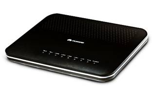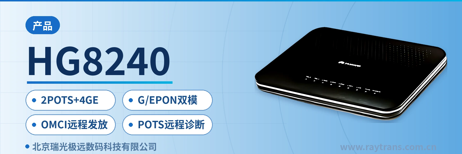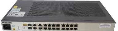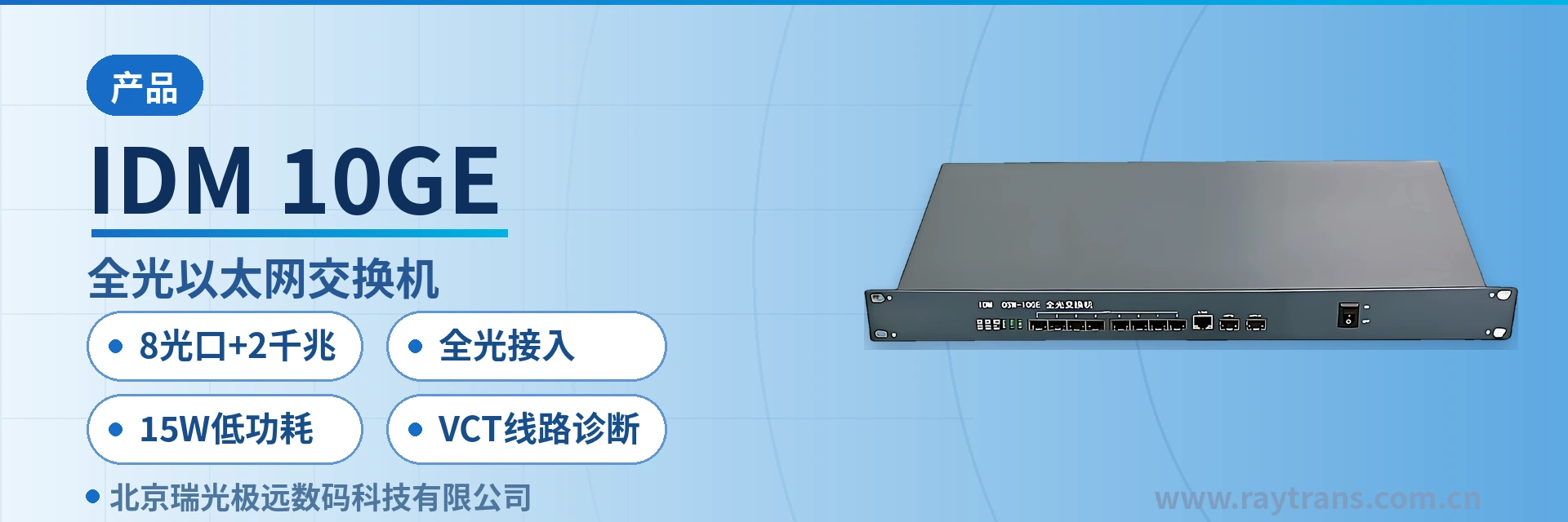
product All-Optical Ethernet Switch/Media Converter Product List
dual-channel isolation
All-optical Ethernet switch/media converter product list, complete in variety.
The all-optical Ethernet switch/media converter product showcase list is a summary of access-layer devices compiled by Beijing Raytrans, with 18 models arranged in five groups: basic optical-to-electrical conversion, dual-channel physical isolation, ring network redundancy, PoE power supply, and multi-service interfaces. This media converter product showcase list specifies, row by row, the number of optical ports, the number of electrical ports, and the services carried for each model, so that on-site selection can be made directly by service type.
Key Specifications at a Glance: 18 models · dual-channel physical isolation · ring network self-healing · 30W per-port PoE · 4-channel RS232/RS485 serial ports · 1U rack-mounted with 2 Gigabit and 8 Fast Ethernet optical ports
How is this media converter product list grouped?
The grouping is based on the primary problem to be solved on site, not on the number of ports. Models that only need to convert electrical signals into optical signals for long-distance links fall into the basic optical-to-electrical conversion group; models where two services must be physically separated fall into the dual-channel physical isolation group; models requiring link failure self-healing fall into the ring network group; models where end devices need power fall into the PoE group; and models that also need to connect serial ports, telephones, or on/off signals fall into the multi-service group. As a media converter manufacturer, Raytrans arranges its entire product line according to this logic, making it easy to quickly locate the right model during selection.
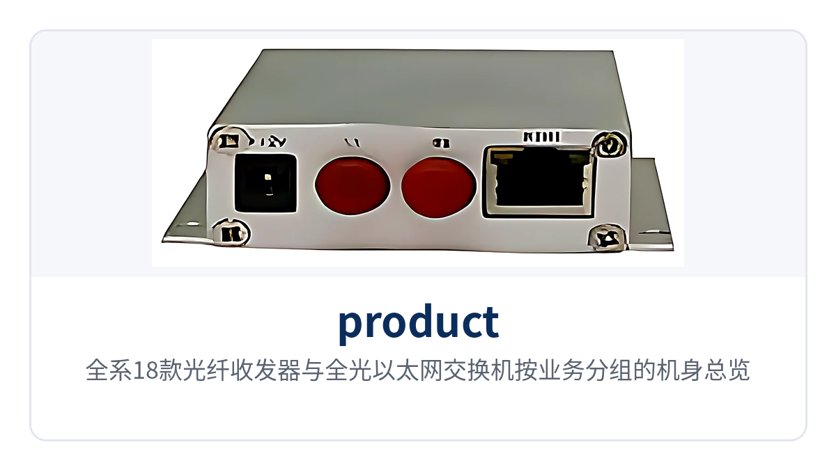
Figure 1: Overview of the chassis of all 18 media converters and all-optical Ethernet switches grouped by service
| Group | Models covered | Common capabilities |
|---|---|---|
| Basic optical-to-electrical conversion | IDM-OPT4FE, IDM OPT2GE, IDM DOPT-2GE | Fast Ethernet or Gigabit Ethernet electrical ports interfacing with optical ports; single-fiber or dual-fiber optional |
| Voice and serial port multi-service | IDM IAD02, IDM OPT-3FE4com, IDM OPT-3FE8key | Optical ports receive services while providing telephone, serial port, or on/off signal interfaces |
| Dual-channel physical isolation | IDM NTD400, IDM GTD400 | Dual optical ports at dual wire-speed; two services physically isolated and do not interfere with one another |
| Ring network dual-channel isolation | IDM NTD400C, IDM GTD400C | Dual-channel physical isolation combined with a ring network structure; link failure self-healing |
| PoE power supply access | IDM POE-M4, IDM POE-M04, IDM POE-M8, IDM POE-M08, IDM POE-M08plus, IDM POE-M8plus, IDM POE-M08plus1 | Four or eight RJ45 ports supplying power per IEEE 802.3af/at, 30W per port |
| All-optical Ethernet switching | IDM SW2G8F | 2 Gigabit optical ports and 8 Fast Ethernet optical ports, SFP slots, eliminating paired media converters |
Overview of optical ports, electrical ports, and service capabilities of the 18 models
The table below lists the 18 models in numerical order, with the number of optical ports, the number of electrical ports, and additional service interfaces itemized, forming a complete product showcase. When checking, first confirm whether the number of optical ports can cover the number of on-site fibers, then check whether the electrical ports and service interfaces are sufficient, and finally confirm whether the PoE power budget and chassis form factor fit into the on-site cabinet.
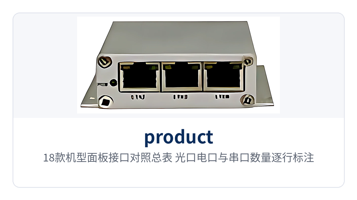
Figure 2: Comparison table of panel interfaces of the 18 models, with optical ports, electrical ports, and serial port counts marked row by row
| No. | Model | Optical ports | Electrical ports and service interfaces | Services carried |
|---|---|---|---|---|
| 1 | IDM-OPT4FE | 1 optical port | 4 RJ45 | Four-channel Fast Ethernet media converter, converting between twisted pair and optical fiber |
| 2 | IDM OPT2GE | 2 SFP optical ports, single-fiber/dual-fiber | 2 RJ45 | Dual optical port Gigabit, one for uplink and one for cascading |
| 3 | IDM DOPT-2GE | 2 SFP optical ports, single-fiber/dual-fiber | 2 RJ45 | Gigabit chain network type, dual optical ports connected end to end to form a chain |
| 4 | IDM IAD02 | 1 optical port | 4 RJ45 and 2 telephone lines | Built-in IAD, VoIP telephone and Fast Ethernet transmitted over the same fiber |
| 5 | IDM POE-M08plus1 | 3 SFP Gigabit optical ports | 8 RJ45 and 4 RS232/RS485 serial ports | Gigabit access switch form factor, serial port server provided |
| 6 | IDM OPT-3FE4com | 1 optical port | 3 RJ45 and 4 serial ports | 1 optical, 3 electrical, 4 serial ports, Fast Ethernet rate |
| 7 | IDM OPT-3FE8key | 1 optical port | 3 RJ45 and 8 on/off signals | 1 optical, 3 electrical, 8 input/output IP network on/off signals |
| 8 | IDM POE-M08plus | 3 SFP optical ports | 8 RJ45, all PoE | Star networking Gigabit, VLAN isolation or shared Gigabit |
| 9 | IDM NTD400 | 2 optical ports, dual wire-speed 100M | 2 RJ45 | Dual-channel physical isolation, two independent services |
| 10 | IDM GTD400 | 2 optical ports, dual wire-speed 1000M | 2 RJ45 | Dual-channel physical isolation, Gigabit wire-speed |
| 11 | IDM NTD400C | 2 optical ports, dual wire-speed 100M | 2 RJ45 | Ring network dual-channel physical isolation, Fast Ethernet |
| 12 | IDM GTD400C | 2 optical ports, dual wire-speed 1000M | 2 RJ45 | Ring network dual-channel physical isolation, Gigabit |
| 13 | IDM POE-M4 | 1 SFP expansion slot and 1 RJ45 uplink | 4 RJ45, all PoE | Uplink selectable between electrical port and optical port |
| 14 | IDM POE-M04 | 1 SFP optical port | 4 RJ45, all PoE | Optical port uplink, four-port power supply |
| 15 | IDM POE-M8 | 1 1000M SFP slot | 8 RJ45, all PoE | Gigabit optical port for chain and tree networks |
| 16 | IDM POE-M8plus | 3 SFP Gigabit optical ports | 8 RJ45 all PoE, optional 4-port serial port server or 2-channel SIP voice gateway | Integrated service optical fiber applications |
| 17 | IDM POE-M08 | 1 Gigabit optical port | 8 RJ45, all PoE | Multi-electrical-port access, 30W per port |
| 18 | IDM SW2G8F | 2 Gigabit optical ports and 8 Fast Ethernet optical ports, SFP slots | No electrical ports | 19-inch 1U chassis, all-optical port aggregation |
What functions does this series provide?
The functions cover five categories: optical-to-electrical conversion, service isolation, link reliability, on-site power supply, and data acquisition, itemized in the table below. The table lists only the capabilities stated in the product documentation; the configuration range is subject to the factory software version. When checking, compare row by row against on-site requirements, and confirm any missing items with the manufacturer separately. In government private network optical fiber communication solutions, Raytrans often deploys fiber optic switches and industrial Ethernet switches together with this series of media converters, and SIP telephones can be connected via the built-in IAD or voice gateway.
| Function | Description |
|---|---|
| Optical-to-electrical signal conversion | Converts Ethernet electrical signals on twisted pair and optical signals on optical fiber, connecting remote stations and the center over a single optical fiber link |
| Dual-channel physical isolation | The two receive/transmit channels in the device each use independent optical ports and electrical ports; the two services are physically separated, and traffic and broadcast domains do not affect each other |
| Ring network self-healing | Dual optical ports connect to a ring optical fiber link; when a fiber break occurs in one section, services are switched to the other direction, and station communication is not interrupted |
| PoE power supply | Supplies power to IP phones and cameras per IEEE 802.3af/at, 30W per port, 65W or 150W for the unit |
| Serial port server | Encapsulates RS232/RS485 data into Ethernet packets, and the center reads on-site devices by IP address and port number |
| On/off signal acquisition | 8 input/output channels, reading access control, water immersion, and smoke sensor contacts, and also outputting signals to drive audible and visual alarms |
| Voice access | Built-in IAD provides 2 telephone lines; telephones communicate after registering per the SIP protocol |
| VLAN isolation | PoE multi-port models can assign ports to different VLANs, or all share the Gigabit uplink bandwidth |
| Chain and star networking | Dual optical port models connect end to end to form a chain; multi-optical-port models form a star network with a central node |
| Plug-and-play | Basic models forward upon power-up, with no need to configure IP addresses or routing tables |
Key specifications and interface standards
The specifications are listed in three groups: interfaces and standards, power supply and power, and chassis and environment, with consistent definitions of the same metric across tables. Rates, port counts, and PoE power are taken from the product showcase documentation; engineering calculations are based on the values in the tables. Items marked "not yet recorded in the knowledge base" must be confirmed with the media converter manufacturer before ordering.
| Item | Parameter/Specification | Description/Applicable Conditions |
|---|---|---|
| Ethernet optical port | SFP slots, single-fiber and dual-fiber modules optional | Fast Ethernet models are 100Base-FX; Gigabit models are 1000Base-X |
| Number of optical ports | 1 to 8, by model | The all-optical fiber switch IDM SW2G8F has 2 Gigabit plus 8 Fast Ethernet |
| Ethernet electrical port | 2 to 8 RJ45 | 10/100Base-TX or 10/100/1000Base-T, by model |
| PoE power supply standard | IEEE 802.3af/at | Supported only by PoE models; powered devices negotiate power per the standard |
| Per-port power supply | 30W | Per-port upper limit; calculate device by device according to the terminal nameplate power |
| Power supply of the unit | 65W (four-port models), 150W (eight-port models) | Overall budget of the unit; the power of multiple terminals must be summed before allocation |
| Serial port | 4 RS232/RS485 | IDM POE-M08plus1 and IDM OPT-3FE4com |
| On/off signal | 8 input/output channels | IDM OPT-3FE8key |
| Voice interface | 2 telephone lines | IDM IAD02, IDM POE-M8plus optional |
| Physical isolation | Dual-channel independent receive/transmit | IDM NTD400, GTD400, NTD400C, GTD400C |
| Chassis form factor | Small desktop or wall-mounted chassis, 19-inch 1U rack | The all-optical fiber switch is 1U rack-mounted |
| Operating temperature and humidity | not yet recorded in the knowledge base | Confirm with the media converter manufacturer according to site environment and power supply conditions |
Four capability tags: dual-channel isolation, ring network redundancy, 30W PoE, 4-channel serial ports
The four capabilities correspond to four types of on-site requirements and become meaningful only when translated into engineering conditions. The table below maps each capability tag to its corresponding project value item by item; when checking, simply match row by row without going through every parameter. The tags themselves are shorthand for on-site communication, and the boundaries in implementation remain subject to the values in the parameter table.
| Capability | Value to the Project |
|---|---|
| Dual-channel isolation | Dual-channel physical isolation lets the two 100M or 1000M services each transmit independently at wire speed, private network services do not interfere with one another, and duplicate addresses on the two sides need no re-addressing |
| Ring network redundancy | With dual-channel physical isolation, the ring automatically switches direction on a fiber break and the link self-heals, so continuous private network operation does not depend on manual attendance on site |
| 30W PoE | Per-port PoE power supply of 30W and 150W for the unit; once the optical fiber reaches the site, the device powers IP telephones and cameras, so no power cabling is needed at the endpoints |
| 4 serial ports | 4 RS232/RS485 serial ports reach the site together with the optical fiber, and data from measurement and control devices and environmental control hosts returns to the center through the same device |
How Does a Basic Optical-to-Electrical Conversion Model Send Electrical Port Services into the Optical Fiber?
The basic model handles one thing: mutual conversion between optical and electrical signals. IDM-OPT4FE uses 4 RJ45 twisted pair interfaces to connect local terminals and 1 optical port for uplink; a single media converter in a weak-current box sends the four 100M electrical port services into the optical fiber, with no need to equip each electrical port with a separate single-port media converter.
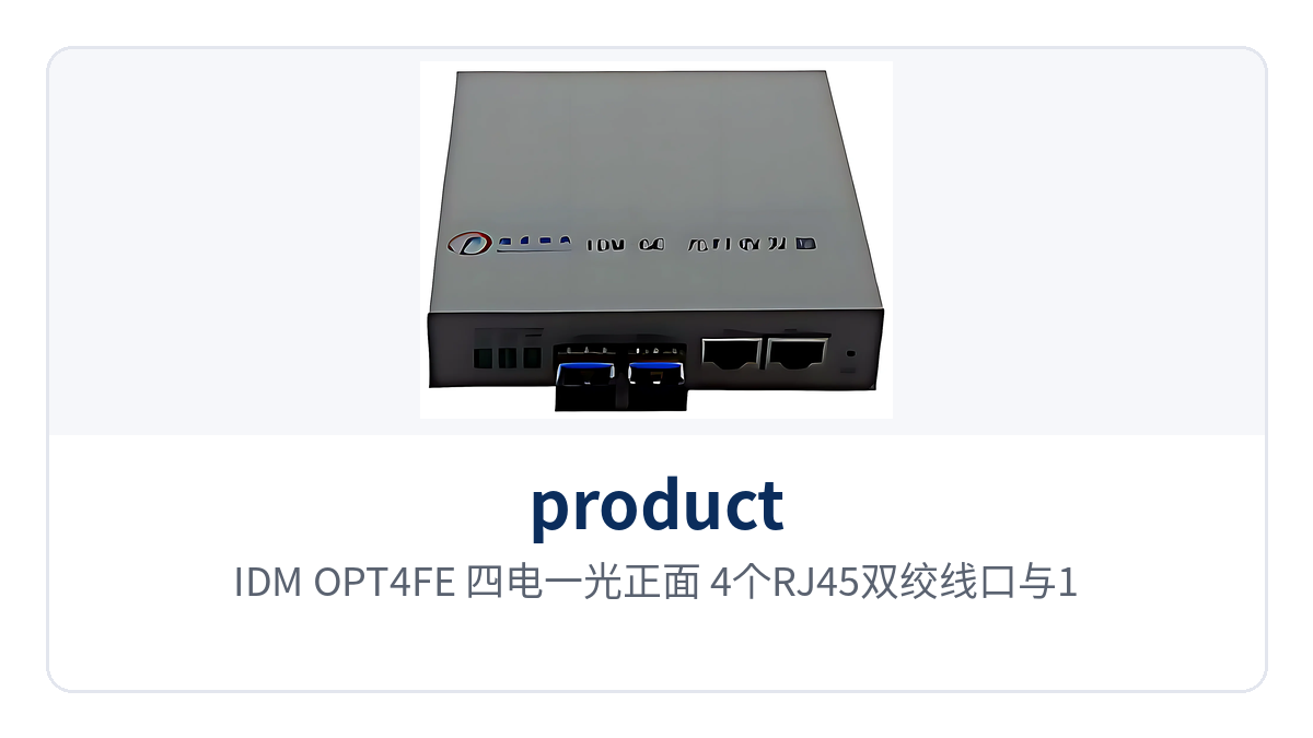
Figure 3: IDM-OPT4FE four electrical and one optical front view, 4 RJ45 twisted pair ports and 1 optical port
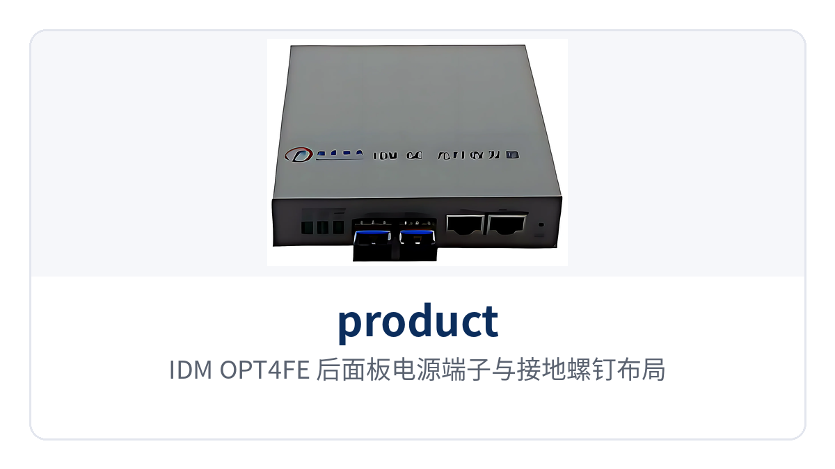
Figure 4: IDM-OPT4FE rear panel power supply terminals and grounding screw layout
The dual-optical-port model adds cascading capability. IDM OPT2GE provides 2 SFP optical ports and 2 RJ45 electrical ports, with one optical port uplinking to the center and the other cascading to the next node; IDM DOPT-2GE also has dual optical ports and dual electrical ports and is connected end to end in a chain network, stringing multiple sites into one chain.
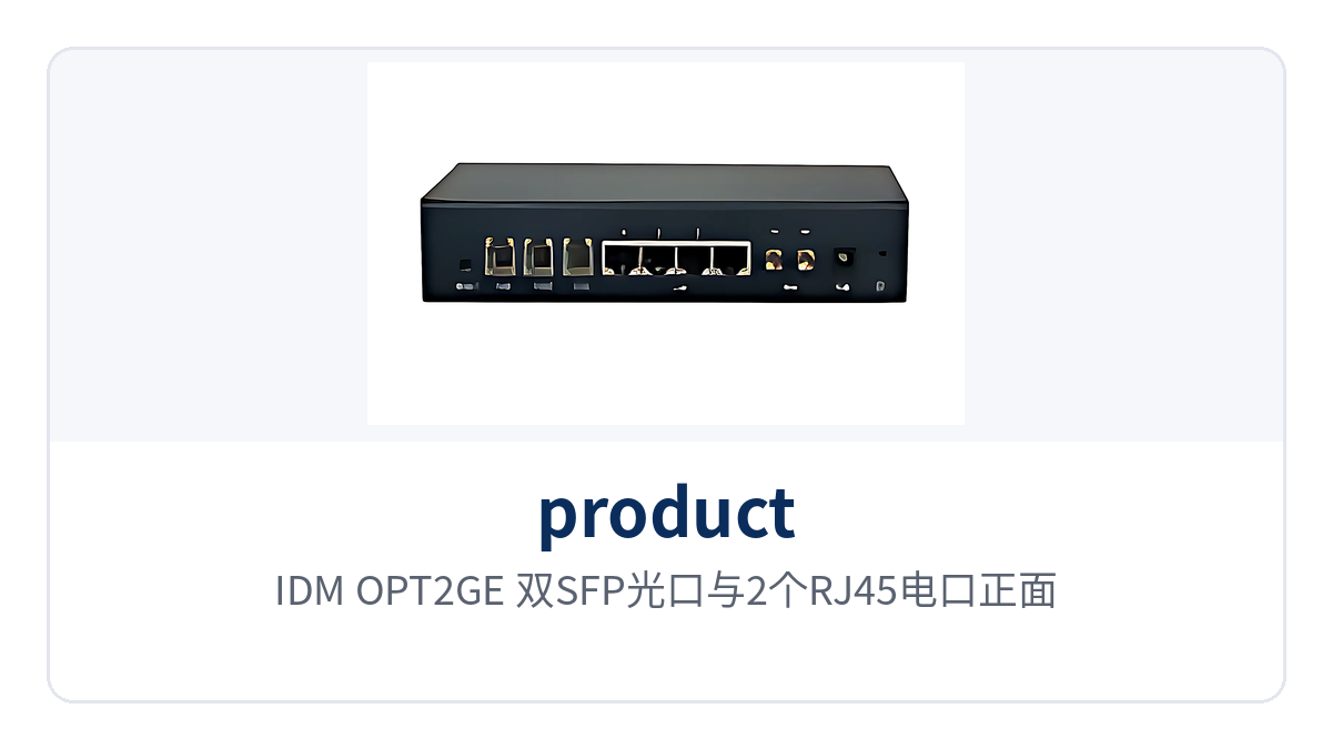
Figure 5: IDM OPT2GE dual SFP optical ports and 2 RJ45 electrical ports front view
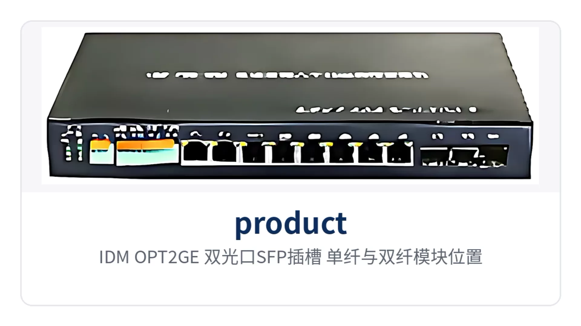
Figure 6: IDM OPT2GE dual optical port SFP slots, single-fiber and dual-fiber module positions
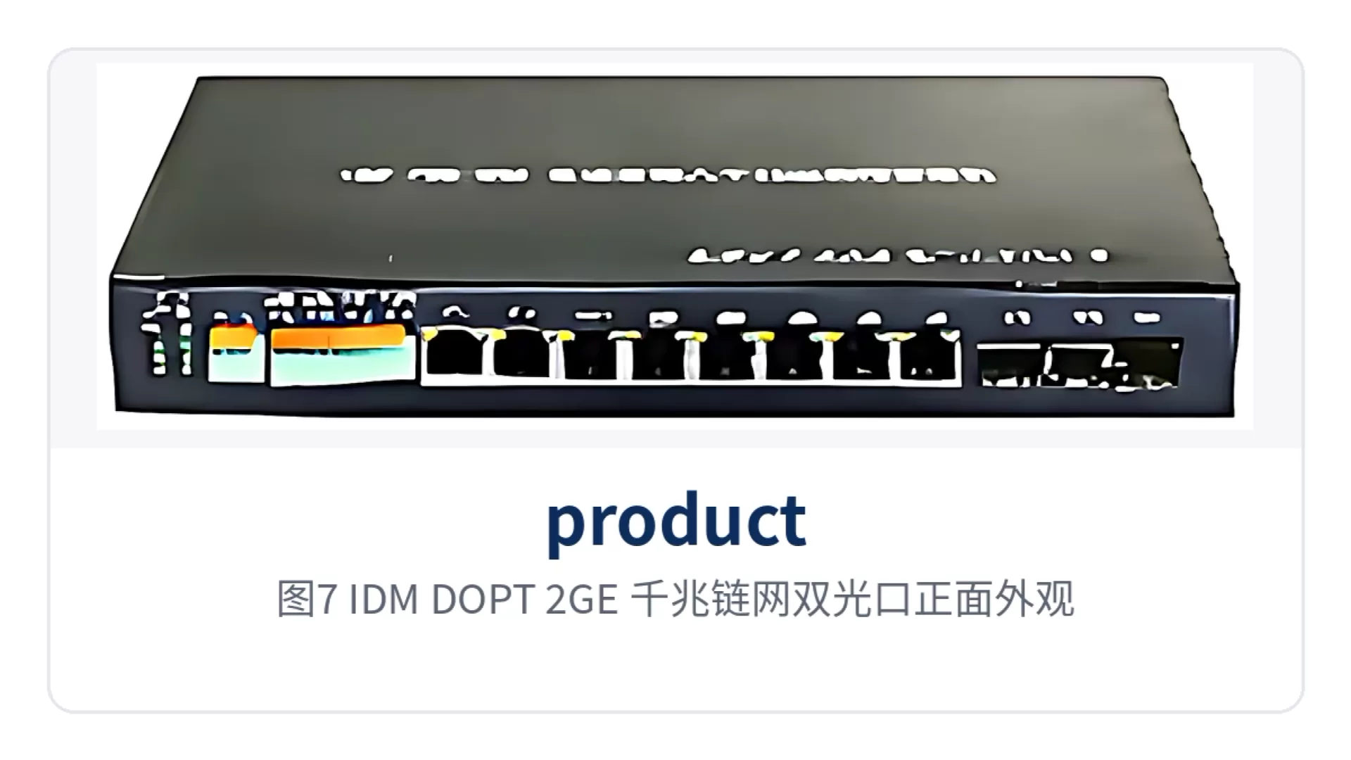
Figure 7: IDM DOPT-2GE gigabit chain network dual optical port front appearance
Optical modules are selected according to link length and number of fiber cores. Both models use SFP slots and accept both single-fiber and dual-fiber modules: a single-fiber module completes receive and transmit over a single optical fiber, while a dual-fiber module uses two fibers, one for receive and one for transmit. Spare parts are unified by the module model already used on site, reducing the variety and the risk of mixed insertion.
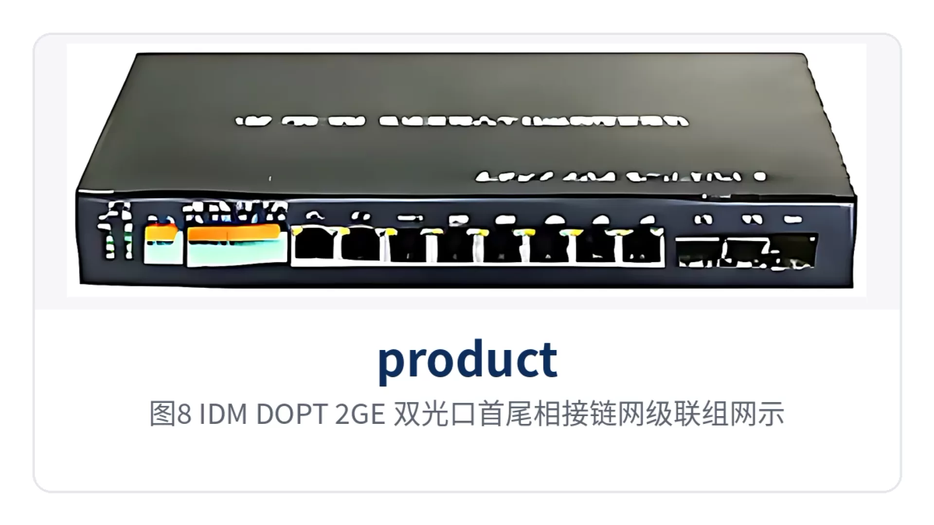
Figure 8: IDM DOPT-2GE dual optical port end-to-end chain network cascading networking schematic
IDM IAD02 adds voice to the media converter. 1 optical port for uplink, 4 RJ45 electrical ports for terminals, and 2 telephone ports for ordinary telephones; the telephones register with the central voice platform over SIP, so the site does not need a separate standalone IAD device, saving one layer of equipment and one power supply access in the cabinet.
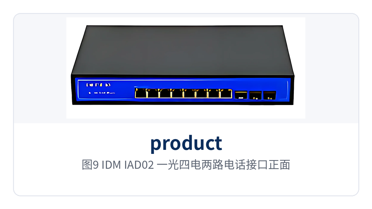
Figure 9: IDM IAD02 one optical, four electrical and two telephone interfaces front view
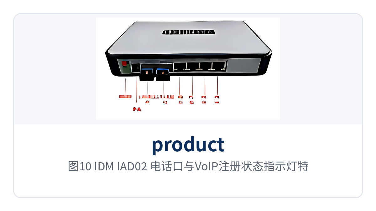
Figure 10: IDM IAD02 close-up of telephone ports and VoIP registration status indicator LEDs
How Does a Dual-Channel Isolated Media Converter Keep Private Network Services from Interfering with One Another?
Dual-channel physical isolation means the device has two mutually independent receive/transmit channels inside, each occupying one optical port and one electrical port, and the two Ethernet paths share no forwarding resources from optical to electrical. IDM NTD400 and IDM GTD400 belong to this category, corresponding to 100M and 1000M wire speed respectively, and the two paths do not contend with each other when both transmit and receive at full speed.
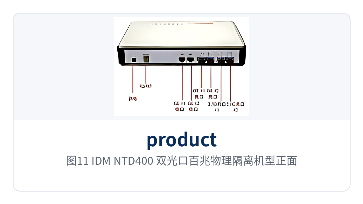
Figure 11: IDM NTD400 dual optical port 100M physically isolated model front view
The point of isolation is the service boundary. When the production control network and the video network are connected to the same device, a traffic burst on one path does not take bandwidth from the other, and a broadcast storm on one side does not spread to the other; when the network segment addresses on the two sides overlap, each can still run independently, with no address re-addressing needed for duplicate addresses.
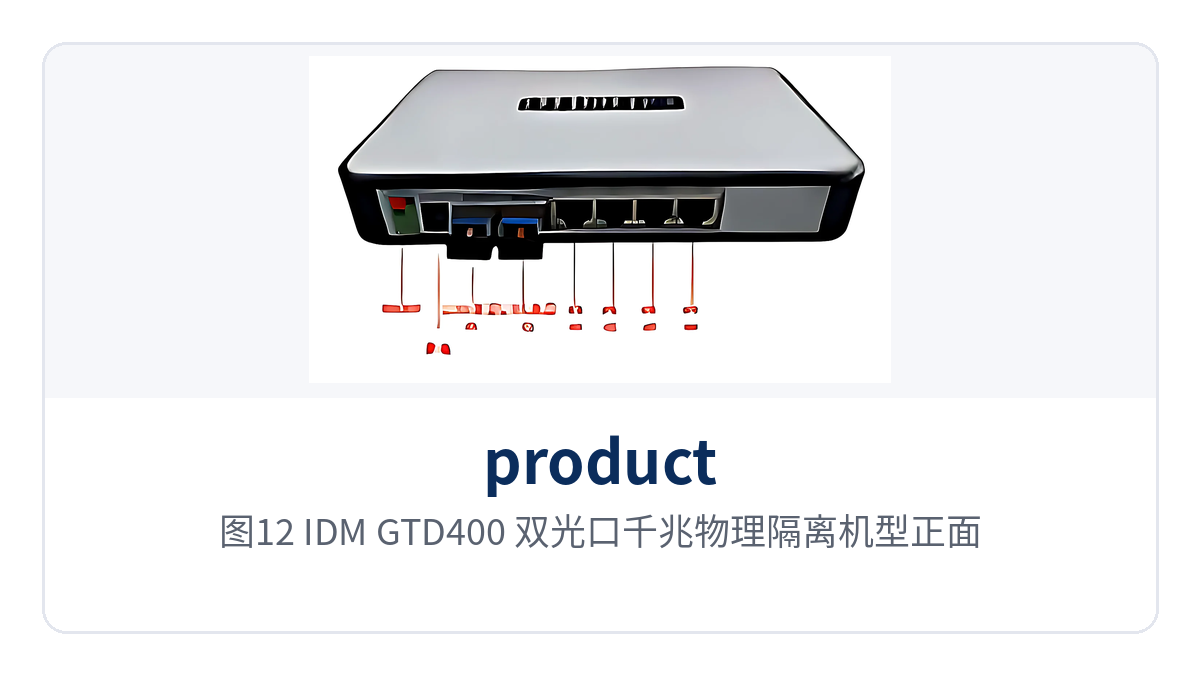
Figure 12: IDM GTD400 dual optical port 1000M physically isolated model front view
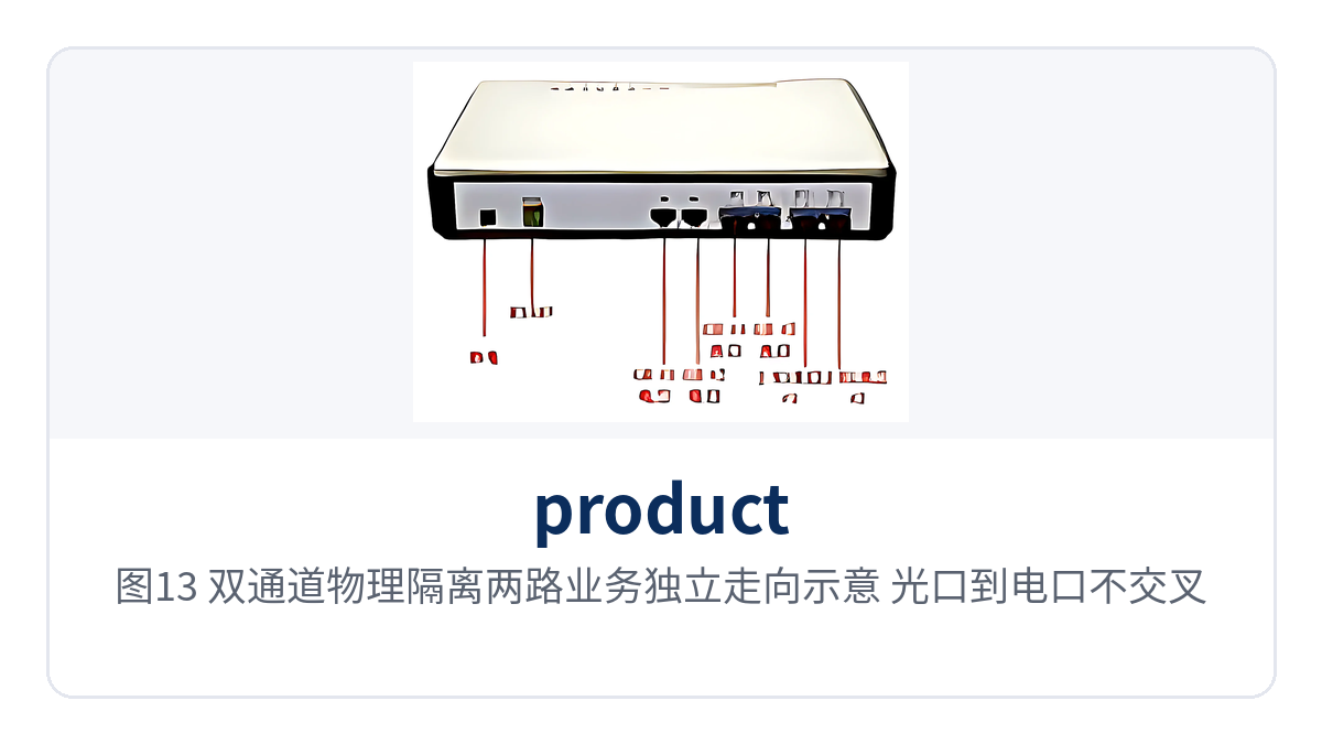
Figure 13: Dual-channel physical isolation schematic of the two services running independently, optical port to electrical port without crossing
The two channels each have independent port indicator LEDs, so on site you can tell which path has dropped without connecting a computer. During maintenance, unplug the patch cord on one side and the other side keeps forwarding as usual; troubleshooting and inspection can be scheduled per channel, with no need to power down the whole unit or stop both services together.
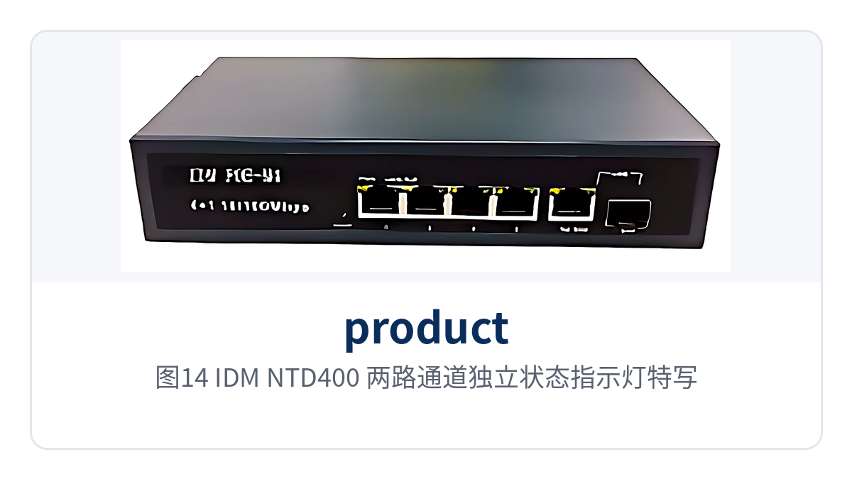
Figure 14: IDM NTD400 close-up of independent status indicator LEDs for the two channels
How Does a Ring Network Redundant Media Converter Achieve Link Self-Healing?
Ring network redundancy builds on dual-channel physical isolation by connecting the two optical ports to the same ring optical fiber link, with one path working and the other on standby under normal conditions. Raytrans IDM NTD400C is the 100M ring network media converter and IDM GTD400C is the gigabit ring network media converter; both keep dual wire speed and physical isolation, and service bandwidth is not degraded by forming the ring.
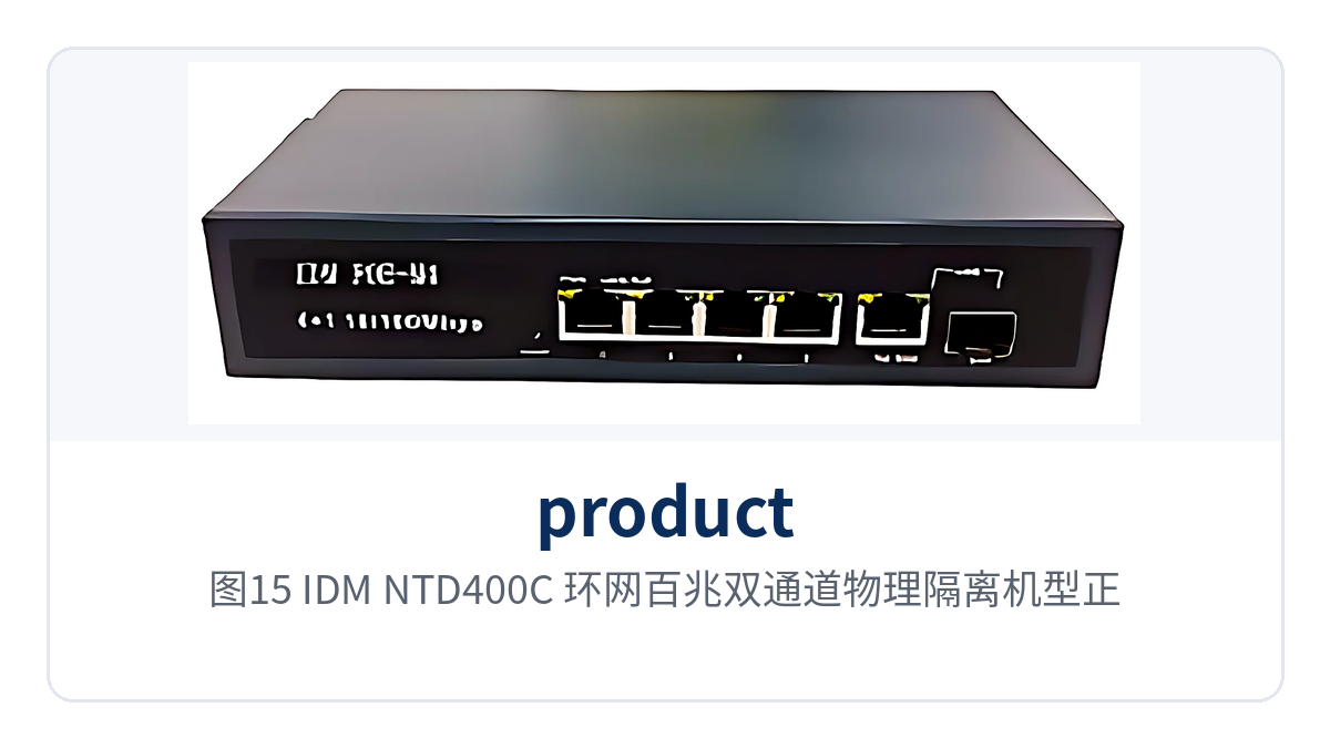
Figure 15: IDM NTD400C ring network 100M dual-channel physically isolated model front view
Link self-healing addresses a single-point fiber break. If any section of optical cable on the ring is dug up or a patch cord comes loose, the media converter switches services to the backup direction, and the site does not need to send anyone to reconnect the fiber; the switchover affects only the traffic on both sides of the breakpoint, and the other sites on the ring keep communicating as usual.
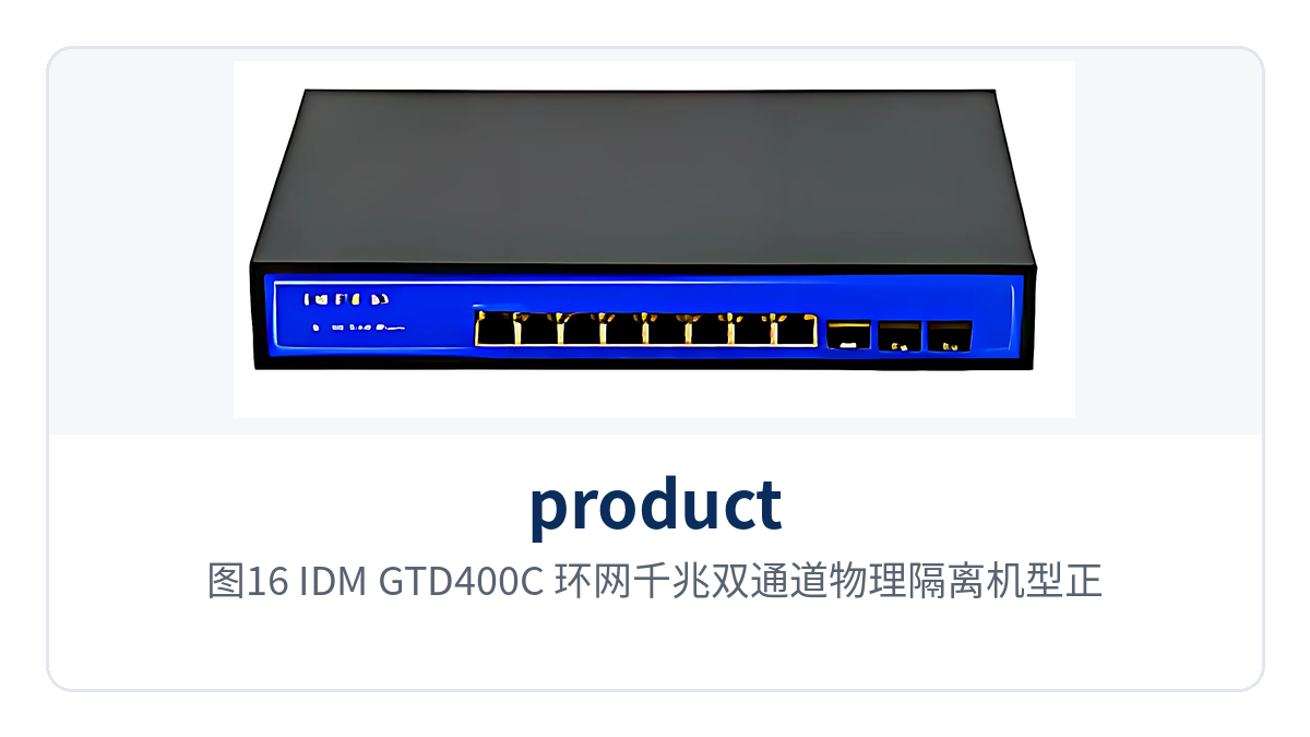
Figure 16: IDM GTD400C ring network gigabit dual-channel physically isolated model front view
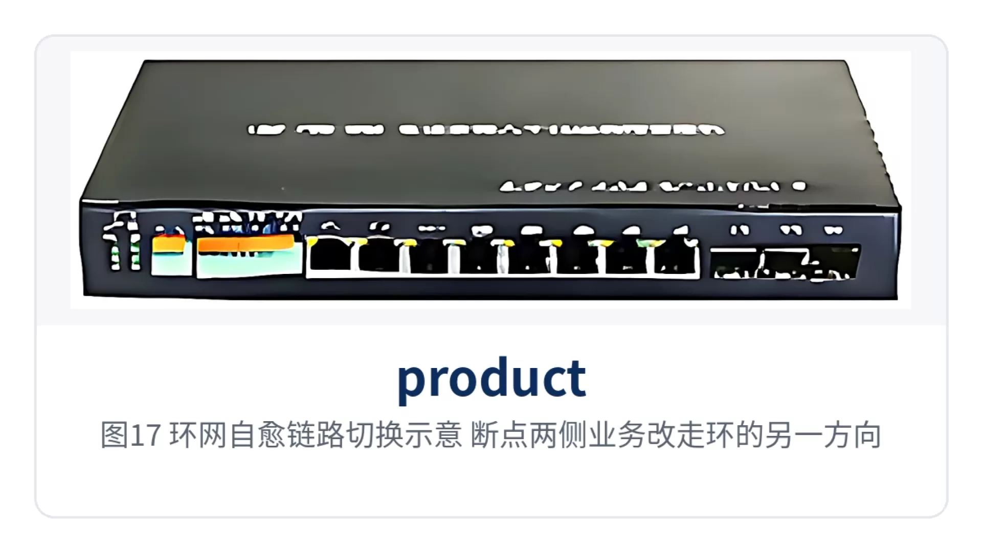
Figure 17: Ring network self-healing link switching schematic, services on both sides of the breakpoint rerouted along the other direction of the ring
In construction, the ring structure takes the form of two fiber directions. At each site, the two optical ports connect to the adjacent sites before and after it; the optical cable is laid once along the line and closed into a ring at both ends. A new site can be added by inserting it into the ring, with no need to pull a dedicated direct optical cable back to the center for it, so the optical cable investment is shared across the number of sites.
How Much Power Can a PoE Media Converter Supply to On-Site Devices?
PoE models supply power per the IEEE 802.3af/at standard, with per-port power supply of 30W and overall power consumption in two tiers, 65W and 150W. IDM POE-M4 and IDM POE-M04 are four-port models with 65W for the unit, while eight-port models such as IDM POE-M8, IDM POE-M08 and IDM POE-M08plus are uniformly 150W for the unit.
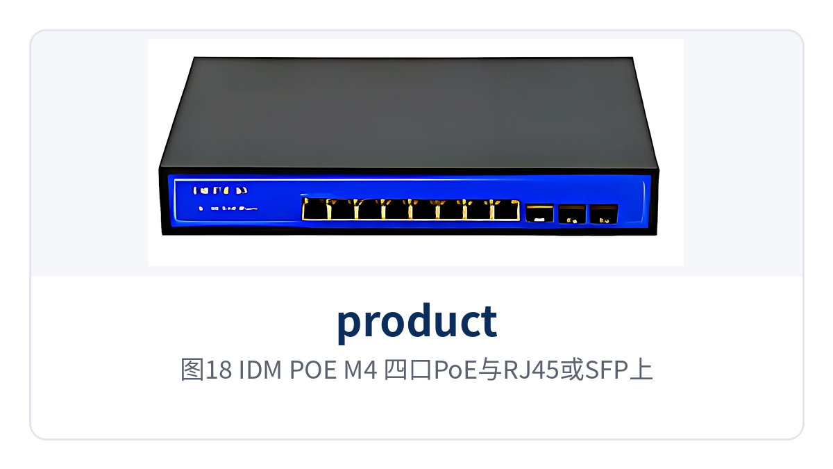
Figure 18: IDM POE-M4 four PoE ports and RJ45 or SFP uplink expansion slot
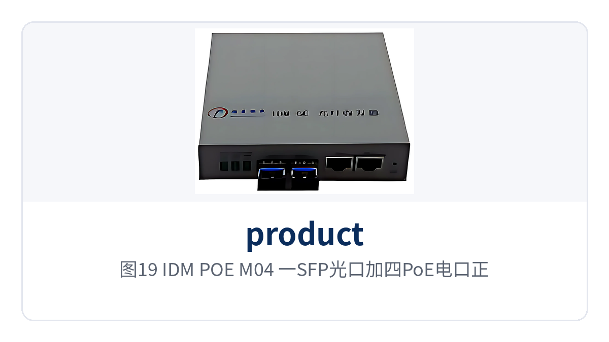
Figure 19: IDM POE-M04 one SFP optical port plus four PoE electrical ports front view
The power budget determines how many devices can be powered. Calculated at the 30W per-port limit and the 150W overall budget of the unit, an eight-port model can power eight terminals of up to 30W each at the same time; the actual number is the sum of the nameplate power of the terminals, and terminals exceeding the overall budget of the unit need a local power supply of their own — do not estimate capacity directly from the number of ports.
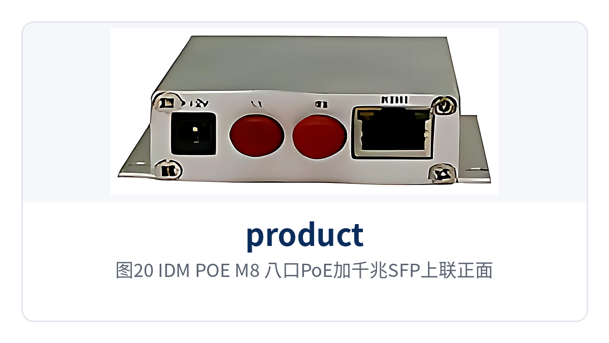
Figure 20: IDM POE-M8 eight PoE ports plus gigabit SFP uplink front view
The uplink method is decided by conditions on the central side. The uplink port of IDM POE-M4 can be selected between an RJ45 electrical port and an SFP optical port: use the electrical port when the central equipment room is on the same floor, and insert an optical module when crossing buildings or sites; eight-port models uniformly provide a gigabit SFP uplink and can form either a chain network or a star network.
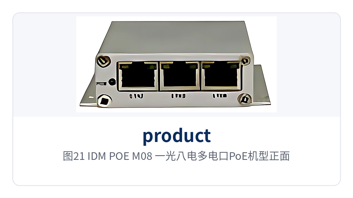
Figure 21: IDM POE-M08 one optical, eight electrical multi-electrical-port PoE model front view
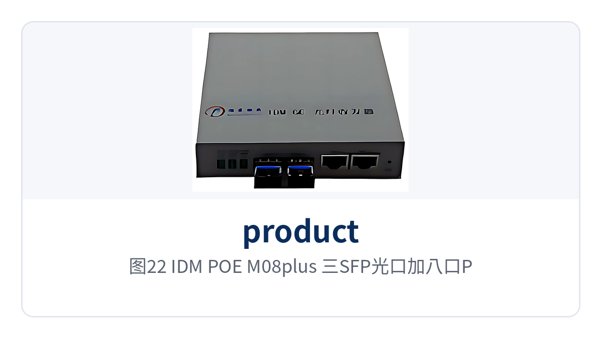
Figure 22: IDM POE-M08plus three SFP optical ports plus eight PoE ports star networking model
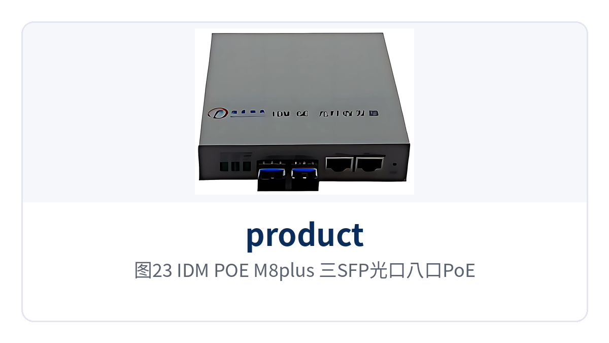
Figure 23: IDM POE-M8plus three-SFP-port eight-port PoE with optional voice gateway
Fiber remote power supply is the direct value of this type of model. Cameras and IP phones are installed on poles, at pitheads, or in corners of station buildings, powered through network cables from PoE ports, so no separate power cables or sockets are laid at the endpoints; power supply access is centralized in the cabinet at one point, and the scope of leakage and power failure troubleshooting is narrowed to the cabinet side.
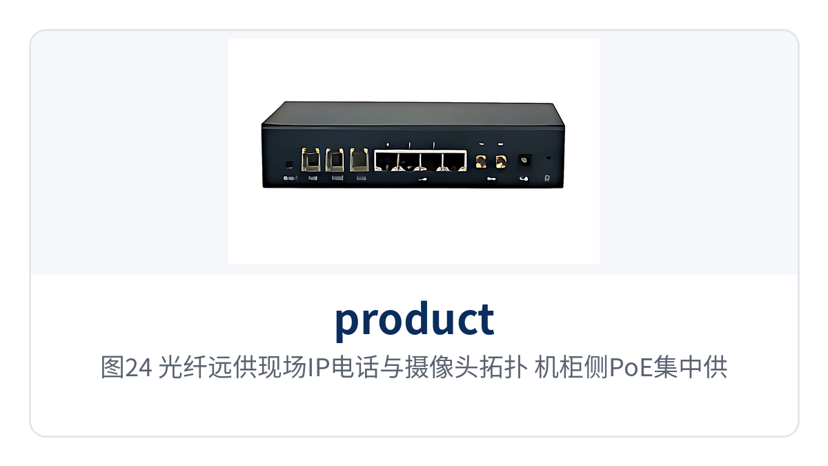
Figure 24: Fiber remote power supply on-site IP phone and camera topology, cabinet-side centralized PoE power supply
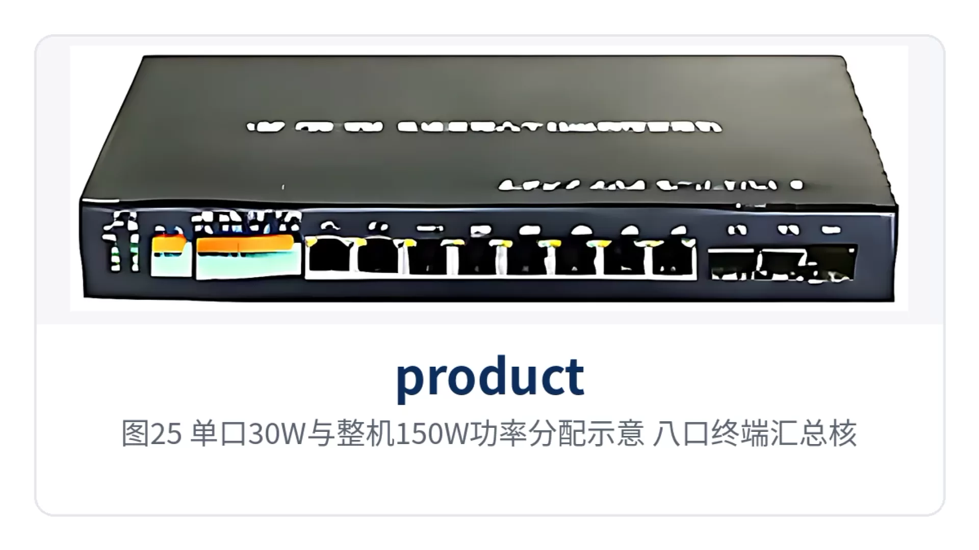
Figure 25: Single-port 30W and overall 150W power allocation schematic, eight-port terminal summary calculation
How do serial ports, voice, and on/off signals work on a single media converter?
Multi-service models build the serial port server, voice gateway, or on/off signal acquisition into the unit itself, so a single optical fiber at the site carries Ethernet as well as serial port, telephone, and on/off signal traffic. IDM POE-M08plus1 provides 4 RS232/RS485 serial ports, IDM OPT-3FE4com provides 4 serial ports, and IDM OPT-3FE8key provides 8 channels of on/off signal input and output.
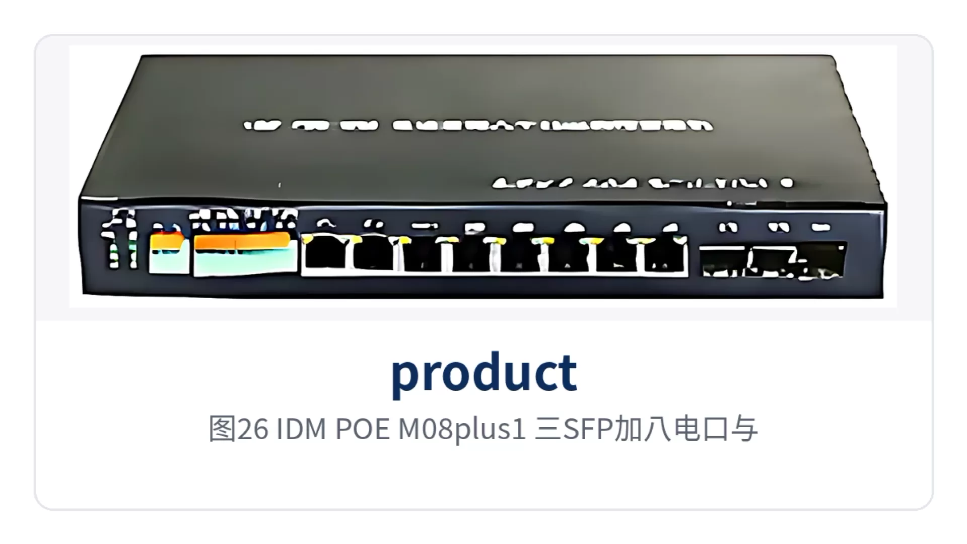
Figure 26: IDM POE-M08plus1 front view with three SFP ports plus eight electrical ports and four serial ports
The role of the serial port server is to encapsulate RS232/RS485 data into Ethernet packets. Measurement and control devices in substations, UPS units in equipment rooms, and environmental monitoring main units mostly output serial port data; once connected, the central side reads them by IP address and port number, and there is no need to pull a separate serial cable from each device to the duty room.
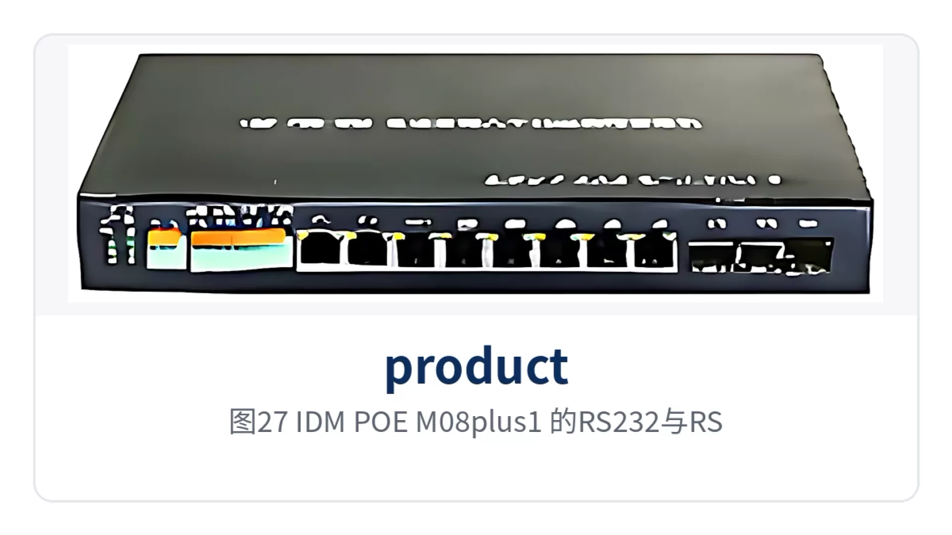
Figure 27: Close-up of RS232 and RS485 serial port terminal wiring on IDM POE-M08plus1
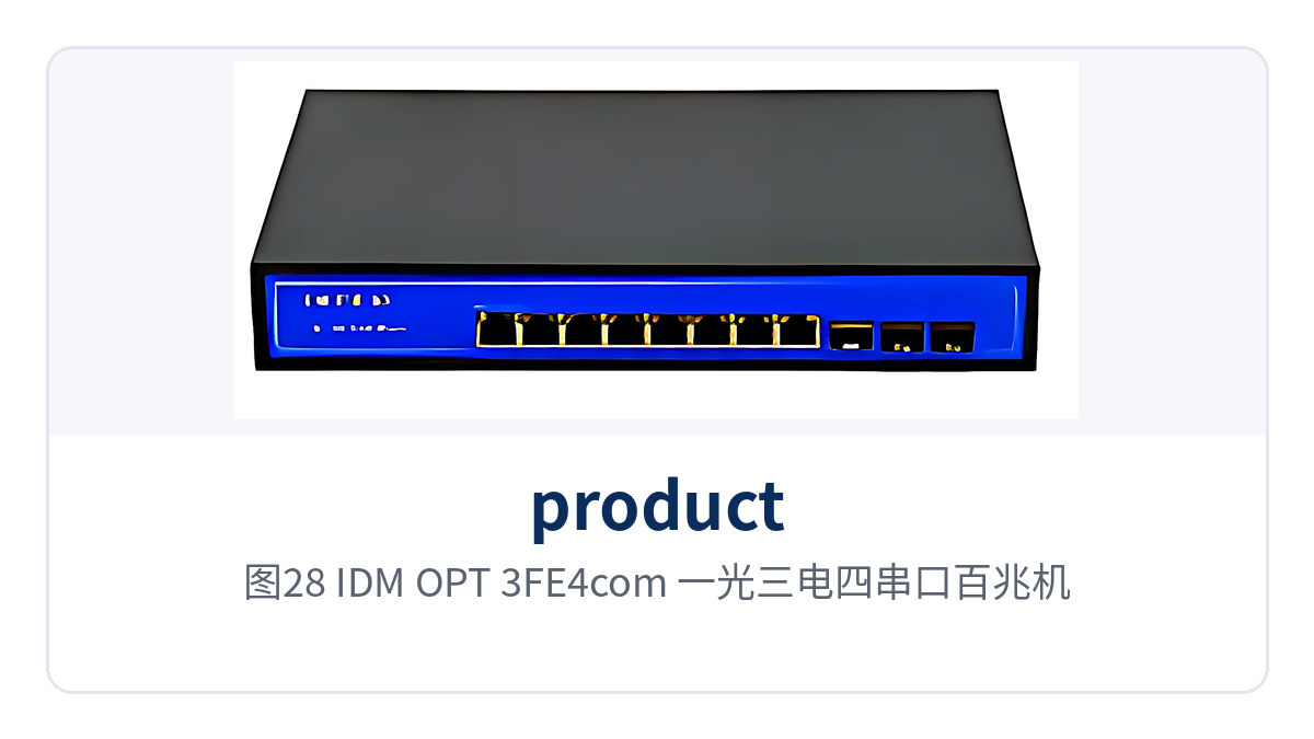
Figure 28: IDM OPT-3FE4com front view, one-optical three-electrical four-serial-port Fast Ethernet model
Voice and on/off signals work the same way. IDM POE-M08plus1 and IDM POE-M8plus can be optionally fitted with a voice gateway, and SIP telephones register over SIP for calls; the 8 channels of on/off signal on IDM OPT-3FE8key can directly read access control, water leak sensor, and smoke detector contacts, and can also output control signals to drive audible and visual alarms, with contact status viewed by site on the central side.
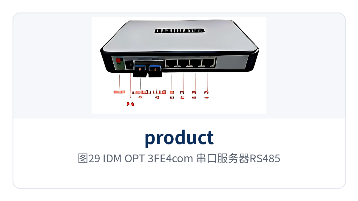
Figure 29: IDM OPT-3FE4com serial port server RS485 wiring and protocol conversion schematic
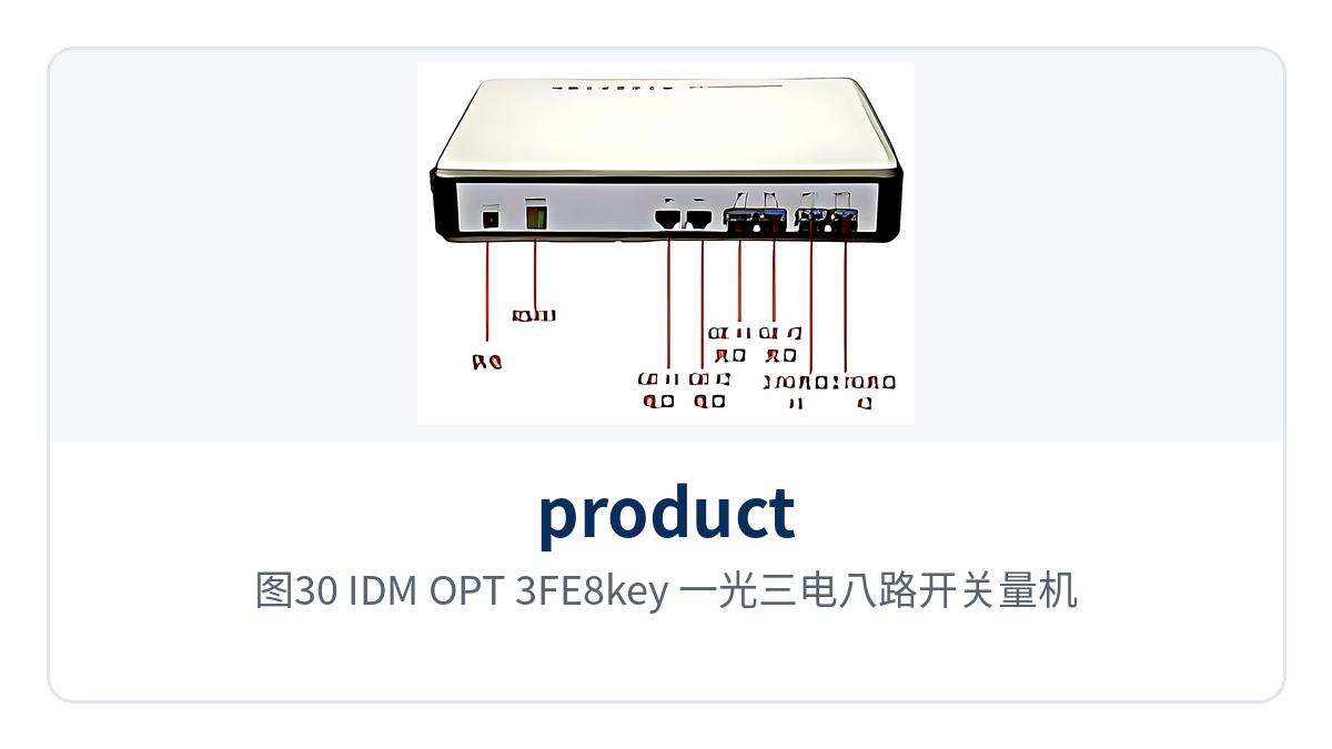
Figure 30: IDM OPT-3FE8key front view, one-optical three-electrical eight-channel on/off signal model
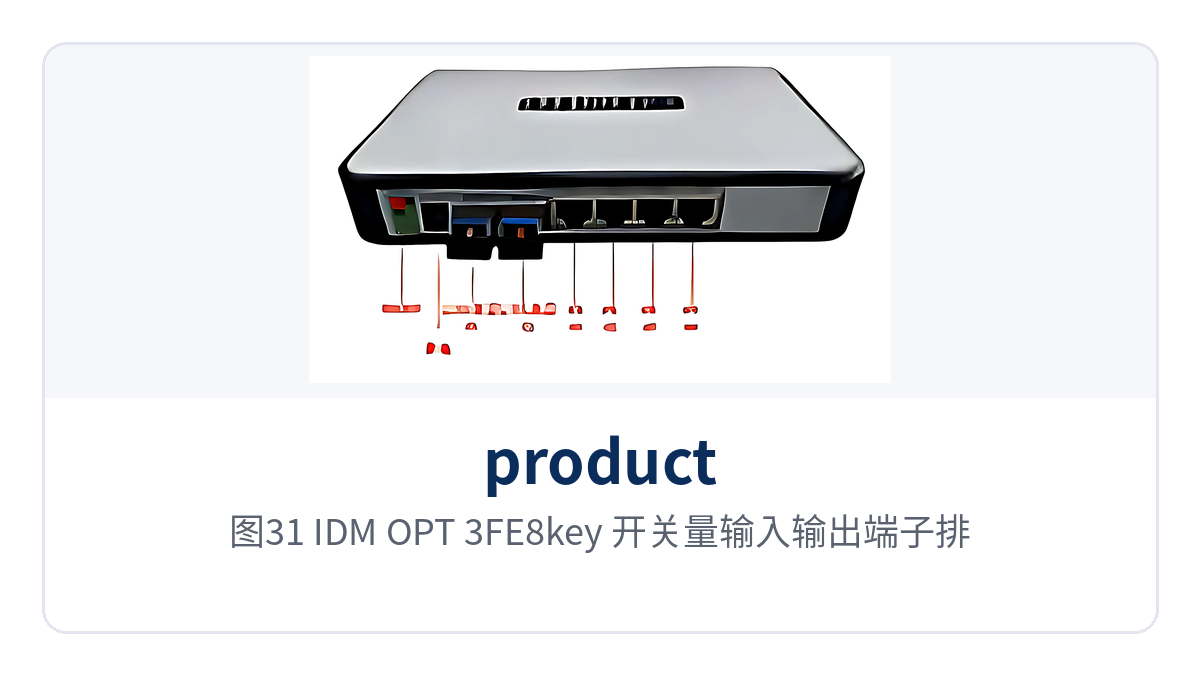
Figure 31: IDM OPT-3FE8key on/off signal input and output terminal block and site labeling
How does an all-optical Ethernet switch replace paired media converters?
IDM SW2G8F is an all-optical port device in a 19-inch 1U chassis, providing 2 gigabit Ethernet optical ports and 8 Fast Ethernet optical ports, all as SFP slots that accept both single-fiber and dual-fiber modules. The 8 channels of Fast Ethernet optical service go directly into the device, so the central side no longer needs a separate media converter for each fiber, and the product showcase is more concentrated.
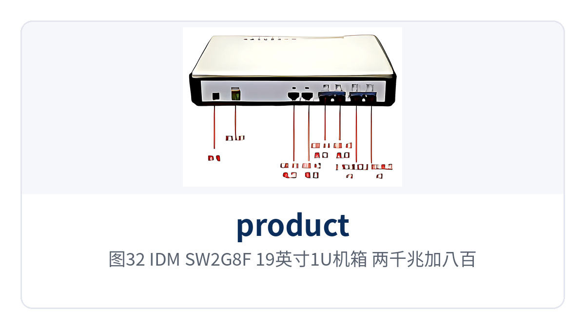
Figure 32: IDM SW2G8F 19-inch 1U chassis front view with two gigabit plus eight Fast Ethernet optical ports
The replacement effect shows up in cabinet space and points of failure. 8 pairs of media converters require 8 rack positions, 8 power adapters, and twice as many patch cord ports; replaced by one 1U device, only 1 rack position, 1 power feed, and the 8 SFP slots on the device remain, reducing the number of connectors and power supply access points at the same time.
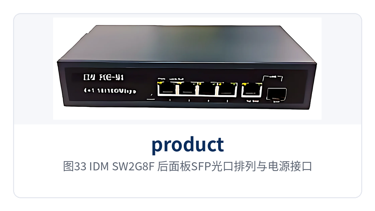
Figure 33: IDM SW2G8F rear panel SFP optical port layout and power connector
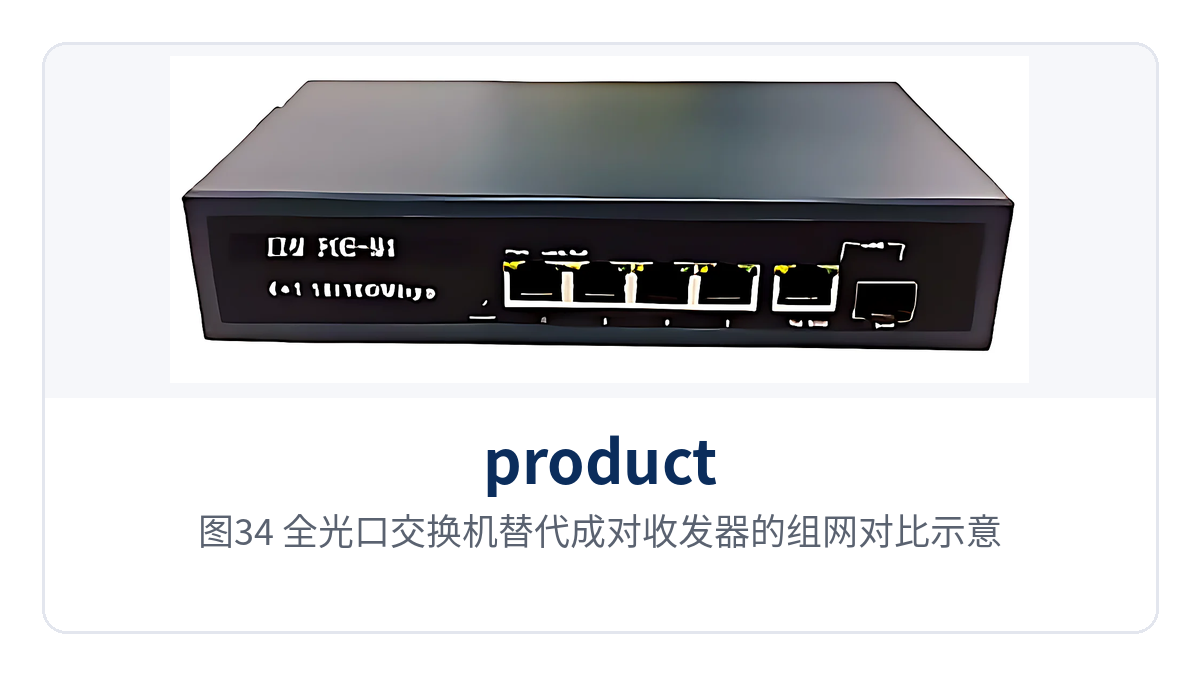
Figure 34: Networking comparison schematic of an all-optical port switch replacing paired media converters
SFP slots let distance and wavelength follow the module. Link length and number of fiber cores vary, so single-fiber or dual-fiber modules of the corresponding wavelength are selected; the same device adapts to new link conditions by changing modules without replacing the unit, and in phased construction, some optical ports can be deployed first and modules added later.
Typical application scenarios
What the three industries share is distributed sites, low service volume per site, and a lack of dedicated duty personnel on site. The practices below give equipment placement and selection intent by industry; during project verification, simply compare against the number of sites and fiber routing, and the specific model is subject to on-site interface and power supply requirements.
Electric power distribution
Substations, ring main units, and distribution terminals are mostly connected by optical cables ranging from several hundred meters to tens of kilometers, with Fast Ethernet as the main service. Dual-channel isolated models carry production control and video services separately, so one device installed in the station cabinet completes two isolated accesses, and the two bandwidths do not contend with each other.
Distribution sites are mostly unattended, with limited power supply and heat dissipation margin. PoE models power IP cameras and IP phones directly in the station, eliminating endpoint power adapters and power supply access points, and the number of cables in the cabinet drops accordingly, so inspection only requires checking port status on the cabinet side.
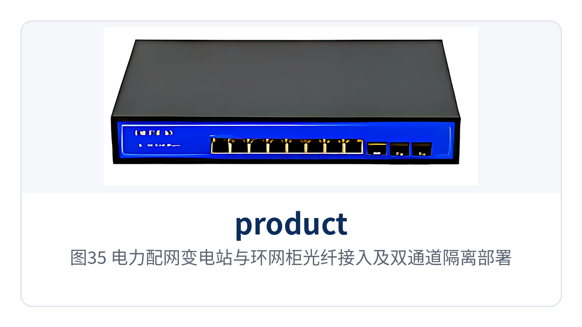
Figure 35: Fiber access and dual-channel isolation deployment for substations and ring main units in electric power distribution
Rail transit
Stations along the line, section substations, and depots are distributed along an entire line, and Ethernet services at each station are uploaded level by level over communications optical cables. Ring network models connect head to tail along the line optical cable, so when a fiber break occurs in one section, services switch to the other side of the ring, and train-operation-related services are not interrupted by a single-point fiber break.
Cabinet space in station communications equipment rooms is fixed, and the fiber optic switch aggregates 8 channels of Fast Ethernet optical service into 1U, so the central side no longer configures a separate media converter for each fiber. Serial port models are used to bring back serial port data from signal controllers, axle counters, and environmental control equipment to the center, reducing local terminals in the duty room.
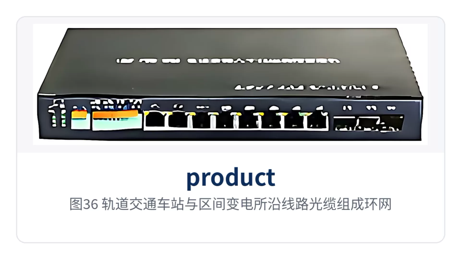
Figure 36: Stations and section substations along a rail transit line form a ring network over line optical cables
Unattended sites
Pitheads, pumping stations, and field pole-side enclosures are scattered, and the enclosure usually has only one mains power feed, with temperature fluctuating with sunlight and season. One PoE model powers both cameras and SIP telephones, while serial port and on/off signal models send environmental parameters back to the center, so no industrial PC needs to be placed on site.
Maintenance is scheduled with remote priority. Serial port data and on/off signal status are readable at the center, and PoE port status is visible on the network management page, so O&M personnel first determine whether the failure lies in the terminal, the network cable, or the optical path, and then decide whether a site visit is needed, reducing ineffective round trips per dispatch.
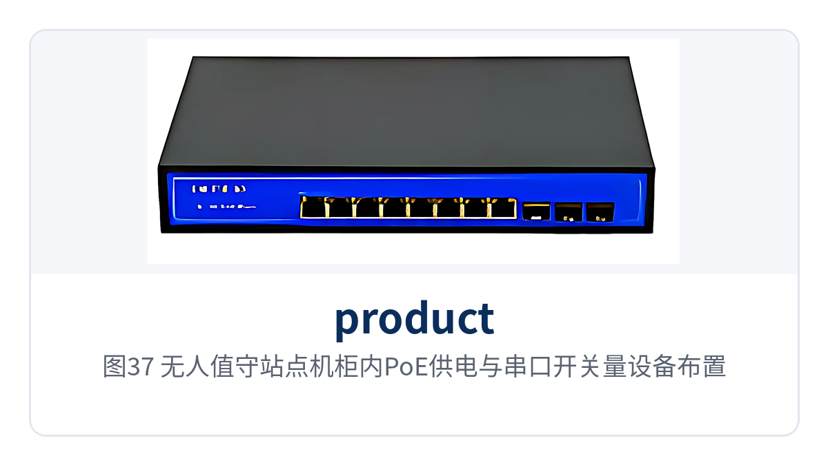
Figure 37: PoE power supply and serial port and on/off signal device layout in an unattended site cabinet
How to select a model according to on-site conditions?
Selection follows five steps, each with clear items to verify; after one pass, the model and quantity are determined. Leave one port of margin, and calculate power and chassis before ordering, so that equipment does not fail to fit the cabinet on site after delivery; for the same project, converge to two or three models as far as possible, and standardize spare parts stocking and on-site training by model.
- Count optical ports: count the number of fibers that need uplink at the site, and determine whether a single-optical-port, dual-optical-port, or 8-optical-port model is needed.
- Determine isolation: when two services need to be physically separated, choose a dual-channel isolated model, giving priority to cases with duplicate addresses or high security zone requirements.
- Check self-healing: for cases where links are laid along the line and fiber break risk is high, choose a ring network model, and select Fast Ethernet or gigabit according to bandwidth.
- Calculate power supply: when there are IP phones and cameras at the endpoints, choose a PoE model, and calculate in summary according to 30W per port and 65W or 150W for the complete unit.
- Add services: when serial ports, telephones, or on/off signals are needed, choose a multi-service model, with port quantity leaving margin according to the number of on-site devices.
| On-site requirement | Recommended model | Selection rationale |
|---|---|---|
| Four electrical port services over one fiber | IDM-OPT4FE | 4 RJ45 connectors and 1 optical port; one unit replaces four single-port media converters |
| Dual optical port uplink and cascading | IDM OPT2GE, IDM DOPT-2GE | 2 SFP optical ports; can be cascaded or form a chain network |
| Two services physically separated | IDM NTD400, IDM GTD400 | Dual-channel physical isolation, with the two channels at independent wire speed |
| Automatic switchover required on fiber break | IDM NTD400C, IDM GTD400C | Ring network dual-channel physical isolation, with self-healing on link failure |
| Endpoint devices need power supply | IDM POE-M08, IDM POE-M8, IDM POE-M08plus | Eight-port PoE, 30W per port, 150W for the complete unit |
| Serial port and on/off signal backhaul | IDM POE-M08plus1, IDM OPT-3FE4com, IDM OPT-3FE8key | 4 serial ports or 8 channels of on/off signal provided with the unit |
| Central-side all-optical aggregation | IDM SW2G8F | 2 gigabit optical ports and 8 Fast Ethernet optical ports, 1U chassis |
Figure 38: Selection Path Diagram by Service Type and Port Quantity, from Optical Port Count to Service Interfaces
Conclusion
As a media converter product list covering 18 models, this list presents four capability lines separately: dual-channel physical isolation, ring network self-healing, 30W PoE power supply, and 4 serial ports, so engineering can determine the model by matching services. Basic models handle optical-to-electrical conversion, isolated and ring network models address service boundaries and continuous operation, and PoE and multi-service models address endpoint power supply and data acquisition.
For electric power distribution networks, rail transit, and unattended sites, clarifying the four items of port quantity, isolation method, power supply budget, and enclosure form first, then selecting models according to the table above, can reduce device model confusion and the variety of spare parts. Carrying Ethernet, serial ports, telephone, and on/off signals over the same optical fiber also lowers the number of devices and power supply access points at a site. As a professional media converter manufacturer, Raytrans (Beijing Ruiguang Jiyuan Digital Technology Co., Ltd.) provides a complete product showcase and selection support covering industrial Ethernet switches and government private network optical fiber communication solutions.