PCM
PCM
The IDM VR5000 Integrated Service Access Device utilizes 2 standard E1 transmission channels (G.703 standard) and adopts the PCM30/31 format to directly provide various user interfaces such as voice, data, and image. It also features non-blocking timeslot cross-connection between the 2 E1 groups and all user interfaces. Additionally, the device supports multiple clock modes to meet the clock requirements of various application environments.
I. Overview
The IDM VR5000 Integrated Service Access Device is one of the PCM integrated multiplexing devices designed by our company using dedicated large-scale integrated circuits. It completes the connection between user terminal devices or between user terminal devices and the public switched telephone network through 2M transmission media.
The device utilizes 2 standard E1 transmission channels (G.703 standard) and adopts the PCM30/31 format to directly provide various user interfaces such as voice, data, and image. It also features non-blocking timeslot cross-connection between the 2 E1 groups and all user interfaces. Additionally, the device supports multiple clock modes to meet the clock requirements of various application environments.
The 2 E1 channels on the main control board can be used to expand the number of voice interfaces to 60, and key units can adopt dual-board redundancy backup.
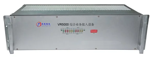
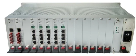
IDM VR5000 Device Image
II. Product Features
19-inch 3U standard chassis with 16 service slots;
Dual 48V power supplies and DXC main control board provide 1+1 hot backup;
The DXC main control board provides user interface access and management, data and signaling cross-connection, system synchronization, and device networking control and management;
The E1 interfaces on the main control board can expand user interfaces. They can connect to PCM equipment from other manufacturers, with 16 timeslots of signaling bits configurable on the main control board. They can also connect to digital program-controlled switch digital E1 signaling such as No.7 and PRI;
Provides a full range of 64K and N*64K interfaces. The service types and quantities can be arbitrarily configured within the chassis, with each slot supporting 8 or 10 channels of 64K services;
Supports FXS/FXO, magneto, 2/4-wire E&M, RS232/RS422/RS485, GSM/CDMA services.
III. Technical Specifications
E1 Interface
Line Rate | 2.048Mbps | Line Code | HDB3 |
Standard Protocol | SupportsITU-T G.703 | Impedance | 75Ω/120Ω |
Frame Structure | PCM30/32 | Signaling | Channel-Associated Signaling |
Ethernet
Transmission Rate | N×VC12 (N≤50) | ||
Standard Protocol | Supports IEEE802.3 | Operating Mode | Full/Half Duplex/Auto-negotiation |
FXO, FXS Interfaces
Audio Range | 300Hz~3400Hz | Compression | A-law per ITU G.711 |
Impedance | Triple complex impedance 200Ω+560Ω//0.1μF | Loop Current | 20mA/channel |
EM2/4-Wire Interface
Audio Frequency Range | 300Hz~3400Hz | Impedance | Balanced600Ω |
Compression Rate | A-law per ITU G.711 | Return Loss | Not less than18dB |
V.24 Interface
Transmission Rate | Asynchronous ≤9600bps; Synchronous 64Kbps | Electrical Characteristics | Complies with CCITT V.28 protocol |
V.35 Interface
Interface Type | RJ-45 | Electrical Characteristics | Complies withITU-T V.35Recommendation |
Transmission Rate | n×64Kbps(n=0~31) | Terminal Interface | Complies withISO2593Specification |
Power Supply and Power Consumption
Power Supply | DC 12V | Power Consumption | ≤12W |
Environmental Conditions
Operating Temperature | -20oC ~+50oC | Relative Humidity | 0~95% (non-condensing) |
IV. Application Example
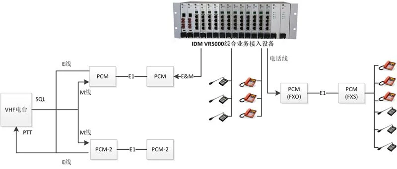
FAQs
What is the working principle of Pulse Code Modulation (PCM)?
Working Principle Pulse Code Modulation is the process of converting a time-continuous…
View answerPCM30 Working Principle: What Is PCM30/32
PCM30 Equipment Working Principle The 30-channel PCM equipment refers to equipment that provides 30 user interfaces and…
View answerWhat are the common problems of PCM equipment in enterprise applications?
At present, PCM equipment has become basically ubiquitous in enterprise network applications.
View answerWhat is E1? How to Use E1
What is E1 The European 30-channel pulse code modulation PCM is abbreviated as E1, with a rate of 2.048Mbit/s.
View answerFrame Structure of 30/32-Channel PCM Primary Group
A communication system consists of transmitting equipment, receiving equipment, and transmission equipment.
View answer