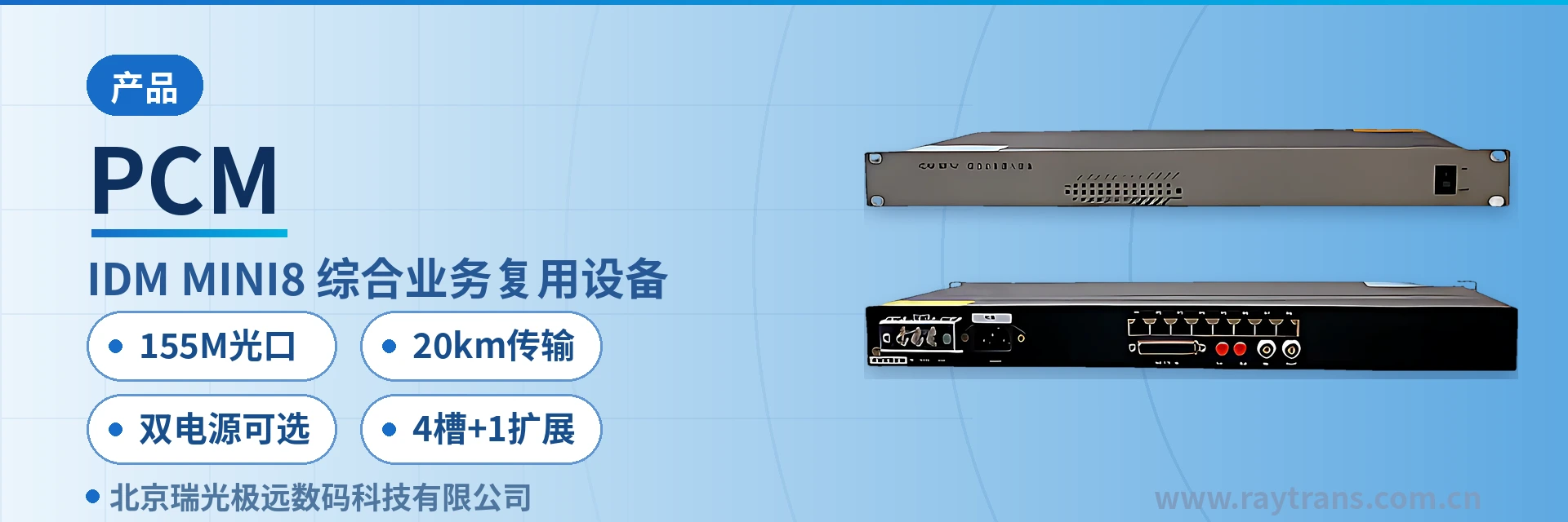
IDM-MINI8
4-slot mixed insertion, voice, data, serial port, 155M optical port, dual power supply optional
The IDM-MINI8 integrated service multiplexer uses a standard 19-inch 1U chassis, provides 4 slot groups + 1 expansion slot group, optional 220 V/-48 V dual power supply, and supports FXS/FXO, magneto, EM 2/4-wire, RS232/RS422/RS485 and other services.
The IDM-MINI8 155M optical port integrated service multiplexer is a card-based integrated service access device developed by Beijing Ruiguang Jiyuan Digital Technology Co., Ltd. (Raytrans). It uses a standard 19-inch 1U chassis and provides 4 slot groups plus 1 expansion slot group, multiplexing 64 kbit/s services such as FXS/FXO telephone, magneto, EM 2/4-wire audio, and RS232/RS422/RS485 serial port onto a 155M optical port or E1 channel for transmission. It is an optical multiplexing device that combines voice and data access.
The optical interface has a receive/transmit rate of 155M/155M, and the single-mode link has a rated transmission distance of 20 km. A single optical fiber between sites is enough to bring voice and data from the remote equipment room back, so remote stations within a 20 km transmission span no longer need cascaded trunk equipment. Power supply can be selected between AC 220 V and DC -48 V; with the optional dual power supply configuration, two power feeds are connected at the same time. The operating temperature is -20 °C to 60 °C, and the overall power consumption is ≤15 W. As a professional optical multiplexer manufacturer, Raytrans adopts PCM multiplexing technology in this model, meeting the access requirements of scenarios such as government private network optical fiber communication solutions, military emergency communications vehicle solutions, and smart mining communication solutions, and it can also be flexibly configured in intrinsically safe mining communication environments.
Key specifications at a glance: 155M optical port · 20 km single-mode · 4 slots + 1 expansion · AC 220 V/DC -48 V dual power supply optional · FXS/FXO, magneto, EM 2/4-wire, and serial port mixed in the same chassis · 19-inch 1U chassis
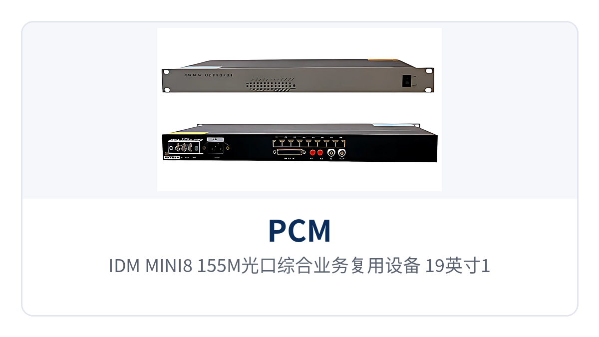
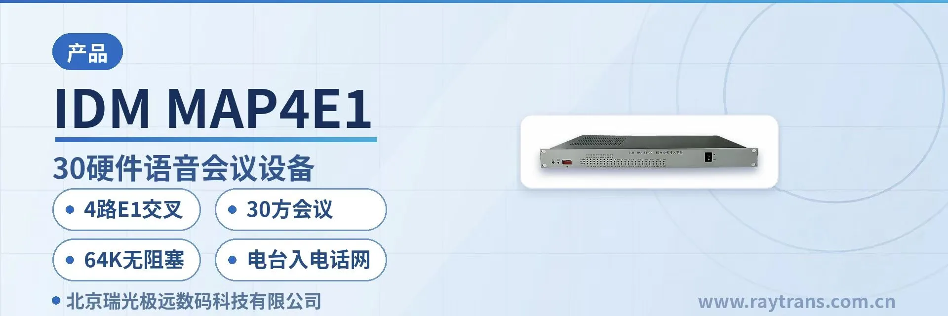
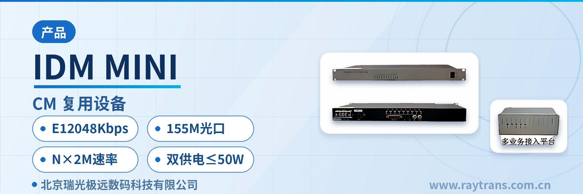
Figure 1: IDM-MINI8 155M optical port integrated service multiplexer — front view of the 19-inch 1U chassis, layout of 4 slot groups and the expansion slot group
What is a 155M optical port integrated service multiplexer?
A 155M optical port integrated service multiplexer refers to an access device that uses a 155M-rate optical interface as the uplink channel and packages multiple 64 kbit/s narrowband services for transmission by time division multiplexing. As a typical PCM multiplexer, the IDM-MINI8 places two uplink channels — the optical interface and the E1 interface — in the same 19-inch 1U chassis. On the user side, voice cards, magneto cards, EM cards, and serial port cards are inserted according to the site service list, and the services of all cards are uniformly multiplexed onto one channel and sent out, making it an integrated service access device that combines product showcase and service bearing.
One device undertakes both service access and transmission conversion, so the number of devices on the site side and the number of cables on the user side decrease accordingly. The common practice of PCM multiplexers is to organize 64 kbit/s voice and data into the E1 channel according to the frame structure. On this mechanism, the IDM-MINI8 compresses the chassis height to 1U and uses 4 slot groups plus 1 expansion slot group to carry different types of service cards, balancing capacity and size as an optical multiplexing device in narrowband service access scenarios.
What services can the 155M optical port integrated service multiplexer access?
The service access capability of the IDM-MINI8 covers five categories: voice, magneto, EM audio, serial port data, and Ethernet. Service cards for each category are selected according to the site service list, and after combination they share one uplink channel. The function items and descriptions are listed in the table below. The specific card types and channel counts of the service cards are subject to the manufacturer's technical documentation and commercial confirmation.
Function | Description |
|---|---|
155M optical port uplink | Optical interface receive/transmit rate 155M/155M, interface type FC (SC and others can be customized), single-mode (multi-mode optional), receive/transmit wavelength 1310 nm/1550 nm, single-mode rated transmission distance 20 km |
E1 channel uplink | Bit rate 2048 kbps, line coding HDB3, compliant with ITU-T G.703, impedance 75 Ω/120 Ω, frame structure PCM30/31, channel-associated signaling |
Voice service access | FXS/FXO interfaces, audio range 300 Hz to 3400 Hz, compression per ITU G.711 A-law, loop current 25 mA per channel |
Magneto service access | Supports magneto telephone access, compatible with magneto telephones and magneto trunks in use in electric power, railway, and mining |
EM 2/4-wire service | Audio range 300 Hz to 3400 Hz, balanced 600 Ω impedance, return loss no less than 18 dB, 2-wire or 4-wire mode selected according to the peer interface |
Serial port data service | RS232/RS422/RS485 serial port access, asynchronous ≤9600 bps, synchronous 64 kbps, electrical characteristics compliant with CCITT V.28, V.35 interface also available |
Ethernet service | RJ-45 interface, transmission rate N×64 kbps (N≤30), supports IEEE 802.3, operating mode full/half duplex/adaptive |
4 slot groups + 1 expansion slot group | Voice cards and data cards can be mixed in the same chassis; the expansion slot group is reserved for new and temporary services |
AC 220 V/DC -48 V dual power supply | AC 220 V and DC -48 V power inputs are selectable; with the dual power supply configuration, both feeds are connected at the same time; overall power consumption ≤15 W |
Key specifications: optical port, E1, Ethernet, and power supply
The key specifications of the IDM-MINI8 cover five parts: optical interface, E1 interface, Ethernet, voice and data interfaces, and power supply and environment, listed item by item in the table below. The parameters in the table are taken from the product documentation. Transmit optical power and receiver sensitivity are used to calculate the link loss margin, and temperature and humidity are given under non-condensing conditions.
Item | Parameter/Specification | Description/Applicable Conditions |
|---|---|---|
Optical interface type | FC (SC and others can be customized) | Optical connector form, customizable according to the patch cord conditions in the equipment room |
Fiber mode | Single-mode (multi-mode optional) | Selected according to the fiber core conditions of the line |
Receive/transmit rate | 155M/155M | Symmetric receive and transmit optical rate |
Receive/transmit wavelength | 1310nm/1550nm | Two wavelengths selectable |
Transmit optical power | -2~-11dBm | Typical range at the transmit side; subject to actual measurement with an optical power meter |
Receiver sensitivity | Better than -36dBm | Used to calculate the link loss margin |
Transmission distance | 20Km | Rated distance under single-mode conditions; can be extended with long-distance optical modules |
E1 bit rate and line coding | 2048Kbps, HDB3 | Standard E1 line rate and line coding |
E1 standard and impedance | Supports ITU-T G.703, 75Ω/120Ω | Coaxial or balanced interface form selected according to the site |
E1 frame structure and signaling | PCM30/31, channel-associated signaling | Primary group frame structure; voice channel status is carried along with the voice time slots |
Ethernet interface | RJ-45, N×64Kbps (N≤30) | Supports IEEE802.3, full/half duplex/adaptive |
FXS/FXO interface | 300Hz~3400Hz, ITU G.711 A-law | Three-element complex impedance 200Ω+560Ω//0.1μF, loop current 25mA per channel |
E&M 2/4-wire interface | 300Hz~3400Hz, Balanced 600 Ω | Compression: ITU G.711 A-law; return loss no less than 18 dB |
Serial port and V.35 interface | Asynchronous ≤9600bps, synchronous 64Kbps; n×64Kbps (n=1 | The serial port complies with CCITT V.28, and the V.35 terminal interface complies with ISO2593 |
Power supply mode | AC220V/DC-48V | Dual power supply optional configuration, with two power feeds connected simultaneously |
Overall power consumption | ≤15W | Upper limit of overall power consumption including service cards |
Operating temperature and humidity | -20℃~60℃, ≤90% (non-condensing) | Equipment room and field cabinet environments |
Chassis dimensions | 440×230×45 (mm) | Length×Depth×Height, 19-inch 1U standard chassis |
How to configure service cards for 4 slots + 1 expansion slot?
With the 4 slots + 1 expansion slot layout, the approach is to assign a service type to each of the 4 regular slots one by one according to the site service list, and reserve the expansion slot for capacity expansion or temporary services. The slots of the IDM-MINI8 do not distinguish between voice-dedicated and data-dedicated positions: voice cards, magneto cards, EM cards and serial port cards can coexist in the same chassis and are multiplexed for transmission over the same uplink channel. The table below gives one allocation approach by service type; the actual card types and number of channels are subject to the site list.
Slot | Supported service card | On-site service carried | Description |
|---|---|---|---|
Regular slot group 1 | Voice card (FXS/FXO) | Dispatch telephone, analog telephone, trunk traffic | Subscriber line or trunk line is selected according to the site call handling arrangement |
Regular slot group 2 | Magneto card | Magneto telephone, magneto trunk | Suited to magneto telephones in use in electric power and railway networks |
Regular slot group 3 | EM card (EM 2/4-wire) | Audio trunk between switches, audio extension | 2-wire or 4-wire mode is selected according to the opposite-end switch interface |
Regular slot group 4 | Serial port card (RS232/RS422/RS485) | Telecontrol, signal monitoring, data acquisition | Transmitted in parallel with voice services in the same channel |
Expansion slot | Voice card or data card inserted as required | Subsequently added services, temporary services | No need to replace the enclosure or the line when the service type changes |
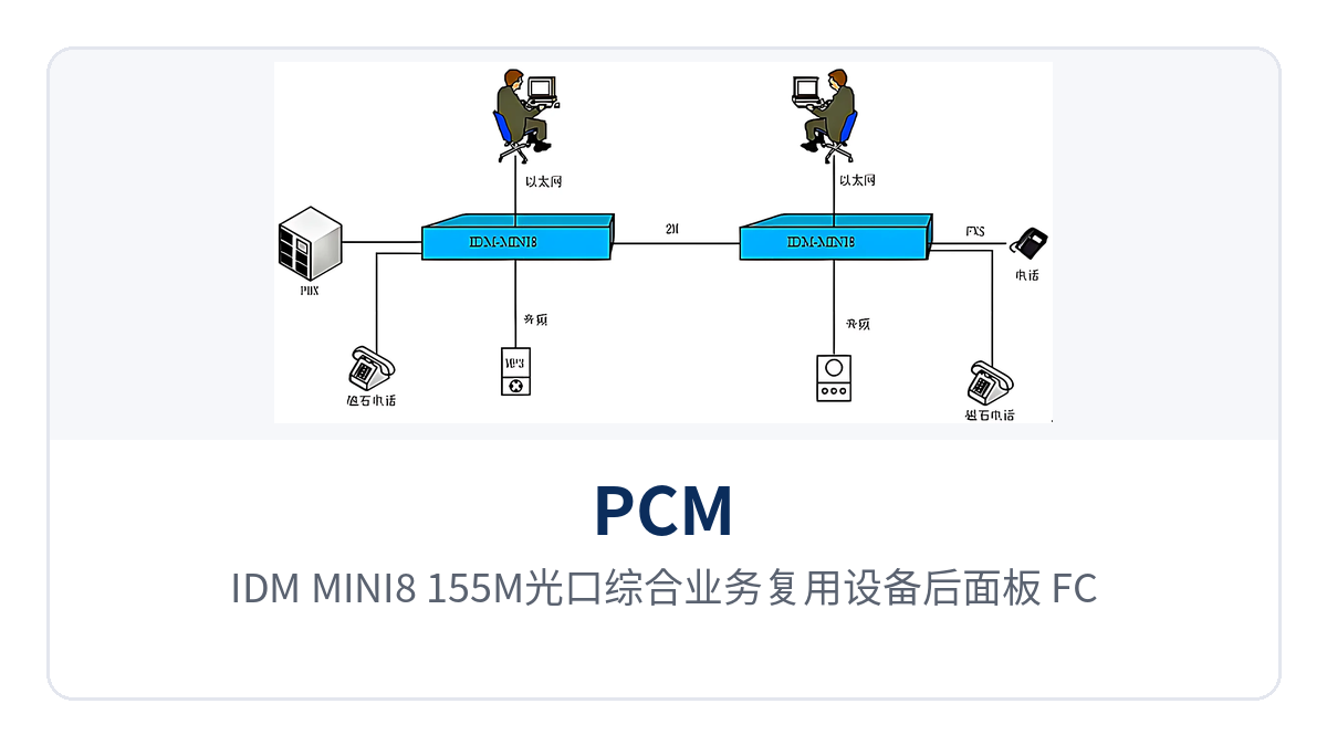
Figure 2: Close-up of the rear panel wiring of the IDM-MINI8 155M optical port integrated service multiplexer — FC optical ports, E1 interfaces and AC/DC dual power supply terminals
The structural basis for mixed insertion is the card-based enclosure and backplane. Service cards are inserted into the slots, user-side wiring lands on the interfaces of the corresponding service card, and the enclosure exposes only optical ports, E1 interfaces and power input to the outside. The number of channels provided by each service card is determined by the selected card type; the product documentation does not list the number of channels card by card, so during configuration please confirm the card type and quantity with the manufacturer according to the site service list, and check the time slot margin in the channel at the same time. Professional optical multiplexer manufacturers represented by Raytrans can flexibly configure such integrated service access devices according to the site service list in government private network optical fiber communication solutions, military emergency communications vehicle solutions and smart mining communication solutions, and can optionally provide intrinsically safe mining communication models to meet the special requirements of underground environments.
How far can a 155M optical port transmit? How to extend when 20 km is not enough
How far a 155M optical port can transmit depends on the selected optical module and the loss margin of the link. Under single-mode conditions, the IDM-MINI8 has a rated transmission distance of 20 km, a transmit optical power of -2 to -11 dBm and a receiver sensitivity better than -36 dBm; the difference between the two is the loss margin available to the link, and the actual achievable distance is calculated by actual measurement with an optical power meter. Direct inter-station connections within 20 km can be met with standard optical module configuration, without adding trunk equipment.
For sites beyond the rated distance, long-distance optical modules can be installed to extend the link further; the module parameters at both ends of the link must match in pairs, and the losses of intermediate patch points, fiber adapters and splice points are all included in the budget. Distance and loss margin are calculated once during selection; replacing modules after on-site splicing is completed will entail adjusting the configuration at both ends. As a typical application of optical multiplexing equipment, this series of optical multiplexers has mature deployments in government private network optical fiber communication solutions, military emergency communications vehicle solutions and smart mining communication solutions, and optical multiplexer manufacturers such as Raytrans can provide full-process support from selection calculation to on-site commissioning.
How to choose between an optical port channel and an E1 channel?
How to choose between an optical port channel and an E1 channel depends on which transmission resource already exists between the sites. Sites with their own optical cables use the optical port channel; one fiber core covers an inter-station distance within 20 km, and services do not need to occupy existing 2M circuits. Sites with existing 2M dedicated lines, microwave or DDN channels use the E1 channel, extending the interface working distance to the remote end without laying new optical cables.
The differences between the two channels are concentrated in channel source, interface form, bandwidth basis and applicable occasions, compared item by item in the table below. During selection, first confirm the on-site resources, then decide which channel to use; both capabilities coexist in the same device. Checking resources before deciding the channel avoids repeated laying of optical cables or adding transmission devices for the same segment of services.
Comparison dimension | Optical port channel | E1 channel |
|---|---|---|
Channel source | Site-owned optical cable | Existing 2M dedicated line, microwave, DDN channel |
Interface form | FC optical interface (SC and others can be customized), single-mode with multi-mode optional | 75 Ω/120 Ω E1 interface, HDB3 line coding |
Transmission rate | 155M/155M symmetric receive/transmit | 2048Kbps |
Service bandwidth | Ethernet N×64Kbps (N≤30) configurable | Voice, data and Ethernet share 2048Kbps |
Applicable occasions | Along-the-line sites with their own optical cables requiring 20 km-level inter-station coverage | Equipment rooms with existing E1 resources requiring extended interface distance |
The same IDM-MINI8 provides both optical interfaces and E1 interfaces, so the model need not be replaced when the transmission conditions at a site change; the equipment room side and the field side can use the same device, spare parts stocking and maintenance processes are thereby unified, and the on-site differences of upgrade projects are also concentrated in the wiring method.
How to configure power supply and cabinet environment for unattended sites
The configuration of unattended sites focuses on two items: power supply and cabinet environment. The power supply mode of the IDM-MINI8 is selectable between AC 220 V and DC -48 V; equipment rooms and attended sites are configured with AC 220 V, while the DC power supply environments of electric power and railway networks and field station buildings are configured with DC -48 V. With the optional dual power supply configuration, two power feeds are connected at the same time, and services are still supported by the other feed when one is abnormal.
As for the cabinet environment, the device has an operating temperature of -20℃ to 60℃, a relative humidity of ≤90% (non-condensing) and an overall power consumption of ≤15 W, and its 1U height occupies one layer in an existing communications cabinet. The same model suits both power supply environments, which means indoor cabinets at substations and field cabinets along the line can share one model, spare parts and on-site wiring methods are unified, and maintenance personnel do not need to stock materials separately by site type.
Differentiated value: 155M optical port, 20 km transmission, optional dual power supply and 4 slots + 1 expansion
The differentiated value of the IDM-MINI8 is concentrated in four areas: channel rate, transmission distance, power supply adaptability and slot density. The four items, together with the corresponding capability and customer value, are shown in the table below. The capability basis in the table is taken from the product documentation; the specific card types and configuration are subject to commercial confirmation.
Differentiation Point | Corresponding Capability | Customer Value |
|---|---|---|
155M optical port | Optical interface with receive/transmit rate of 155M/155M, FC interface with SC and other options customizable, single-mode with multi-mode optional | Connects voice and data from remote stations back over one optical fiber, without occupying existing E1 circuits or cascading trunk equipment |
20km transmission | Single-mode rated transmission distance of 20Km, transmit optical power -2~-11dBm, receiver sensitivity better than -36dBm | Inter-station direct connection within 20Km only requires standard module configuration, reaching from a field remote station to the central equipment room in one hop |
Dual power supply optional | AC220V/DC-48V two power supply inputs optional, overall power consumption ≤15W, operating temperature -20℃~60℃ | AC configuration in equipment rooms and DC configuration in the field; power redundancy reduces service interruption caused by power supply abnormality on one feed |
4 slots + 1 expansion | 4 service slot groups plus 1 expansion slot group, voice cards and data cards mixed insertion | Telephone, magneto, EM audio and serial port services are multiplexed in the same chassis; service changes are handled by swapping cards for capacity expansion, while the chassis and lines remain in use |
Typical Application Scenarios
Electric Power Private Network: Multi-Service Backhaul for Substations and Distribution Terminals
In electric power private networks, substations, switching stations and distribution terminals carry both dispatch telephone services and telecontrol and on-site monitoring data. IDM-MINI8 is deployed in the communications cabinet at the station, merging dispatch telephone, magneto telephone, audio trunk and telecontrol serial port data over the 155M optical port for uplink to the dispatch end or central station, so the station does not need separate devices and cables for each service type.
At the station end, voice cards and serial port cards are inserted according to the service list, while the E1 interface is used to interconnect with existing 2M transmission equipment; one of the two channels is selected according to site resources. The device is configured with DC-48V power supply, and the dual power supply option interfaces with the station's DC power system. The 1U chassis occupies one layer in the existing communications cabinet, and the impact of the upgrade on existing facilities is concentrated in the wiring stage.
Rail Transit Communication: Voice and Data Access for Trackside Sites
In rail transit, stations, depots and trackside sites carry official telephone, low-speed monitoring data and office network services. One IDM-MINI8 is placed at a trackside site, multiplexing on-site voice, magneto telephone and serial port data for backhaul to the station communications equipment room over one optical fiber or one E1 channel, reducing both the number of longitudinal cables and the number of devices on the station side.
Optical fiber links are immune to trackside electrical interference, and inter-station distances of around 20Km are covered with single-mode optical module configuration, with no intermediate devices cascaded between sites. The 1U chassis can be installed directly in the station communications cabinet, with power supply selected according to the AC or DC conditions of the equipment room; with the dual power supply option, two power feeds are connected at the same time, facilitating long-term operation of unattended sites along the line.
Military and Government Private Networks: Rapid Setup of Mobile Command Posts and Duty Posts
In military and government private networks, command posts, duty posts and emergency communications vehicles mainly carry internal telephone, low-speed data and office network services, and there is often no dedicated maintenance personnel on site. IDM-MINI8 adopts a standard 19-inch 1U chassis architecture with card-based service cards. During setup, the uplink channel is first determined as either the optical port or E1, and then voice cards, magneto cards, EM cards and serial port cards are inserted according to the task list; services can be enabled once wiring is complete.
When the site service list changes, the adjustment is completed by replacing or adding service cards in the slots, while the chassis, backplane and existing lines remain unchanged, making the device suitable for phased construction and rolling upgrades. The operating temperature of -20℃~60℃ and overall power consumption of ≤15W support long-term operation in vehicle-mounted cabinets and simple station buildings, with power supply selected according to on-site AC or DC conditions.