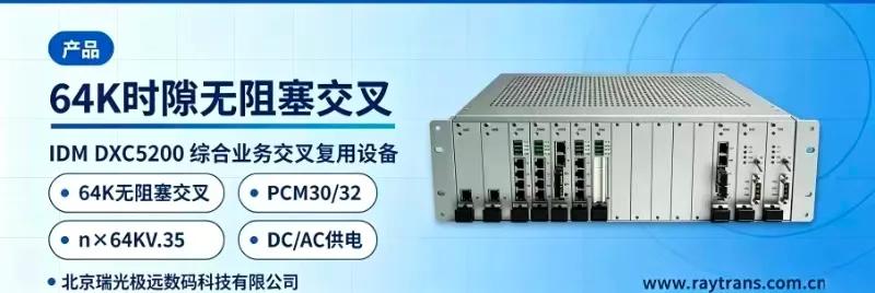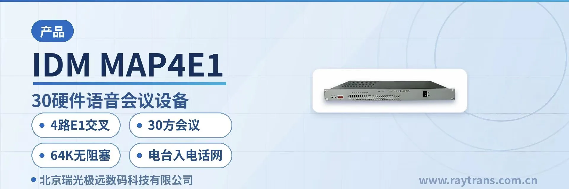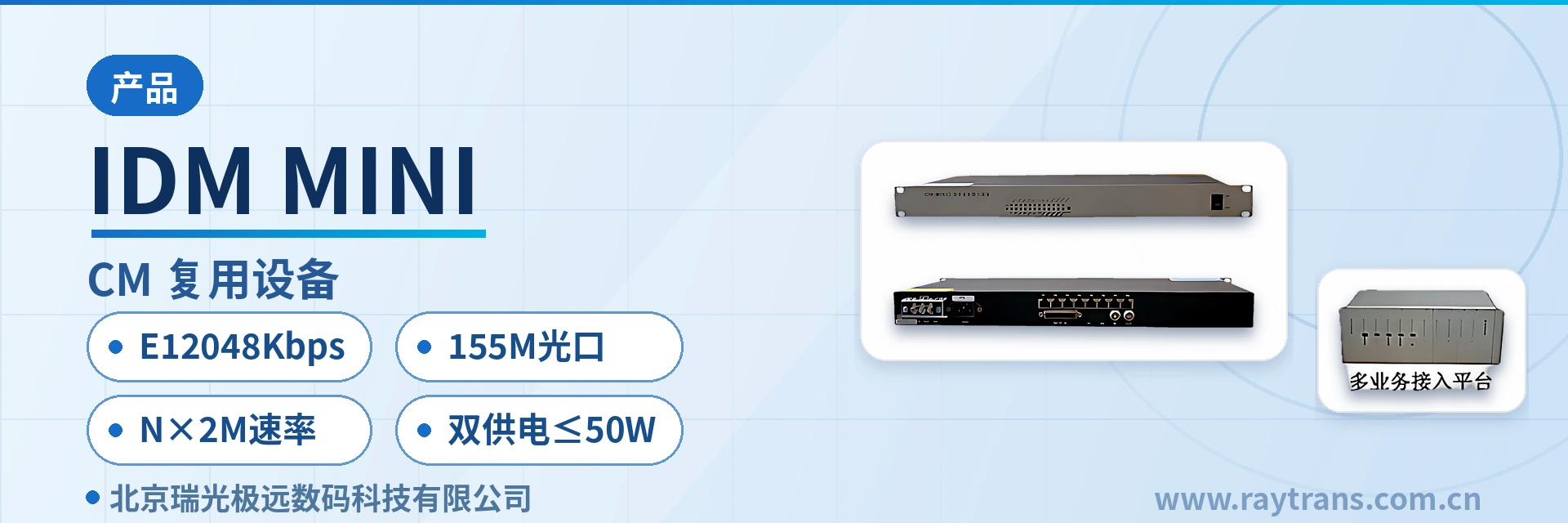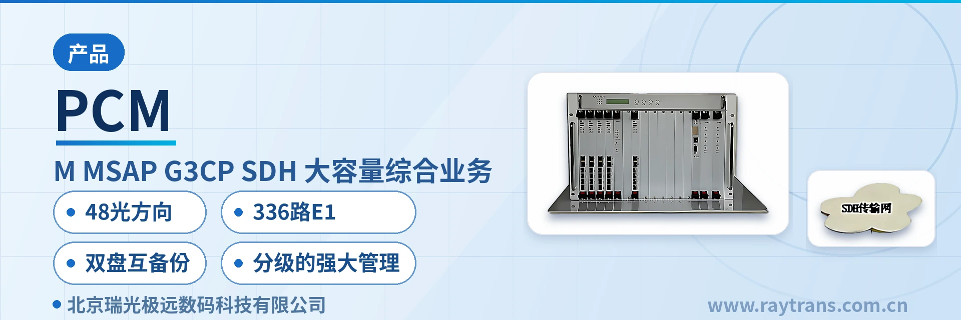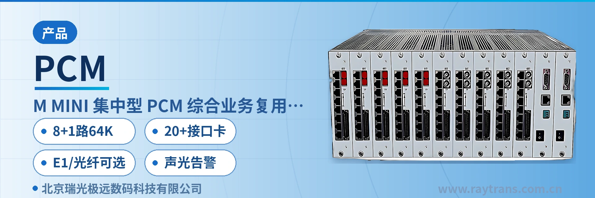
IDM-MINI Centralized PCM Multiplexer
10 user card slots, service changes by card replacement, 8+1 channels of voice, data and Ethernet over one channel
The IDM-MINI centralized integrated service multiplexer can simultaneously transmit 8+1 channels of 64K or n×64K voice and data services over one E1 or optical fiber transmission channel. By converting services such as 10Base-T Ethernet, voice channels, V.35 and V.24 into E1 data streams, it transmits them over an E1 channel or optical fiber channel.
The IDM-MINI 8+1-channel 64K centralized PCM multiplexer is a centralized integrated service access device developed by Beijing Ruiguang Jiyuan Digital Technology Co., Ltd. It adopts an independent structure and carries 8 channels of 64K voice and data services plus 1 channel of N×64K service simultaneously over one E1 transmission channel or optical fiber transmission channel.
The IDM-MINI centralized unit converts 10Base-T Ethernet, voice channels, V.35, V.24 and other services into a unified E1 data stream, which is then sent out over an E1 channel or optical fiber channel. Voice and data at a site share one channel for transmission, so multiple single-service transmission devices no longer need to be installed separately by service type in the equipment room, and the various interface cards shown in the product showcase can therefore be combined flexibly.
Centralized means the chassis organizes services in a user card-based manner: the IDM-MINI centralized model can be configured with 10 user card slots, and the services carried by each card correspond to those of the IDM-MINI single-board model. When service types change, only the cards need to be swapped, not the whole unit. The unit can coordinate networking with other IDM series multiplexing equipment to form chain networks, star networks, tree networks and other structures. When used as optical multiplexing equipment, it can be deployed together with Raytrans series products from Ruiguang Jiyuan, and applies to scenarios such as government private network optical fiber communication solutions, military emergency communications vehicle solutions and smart mining communication solutions.
Key Specifications at a Glance: 8+1 channels of 64K services · 20+ service interface cards · 10 user card slots · E1/optical fiber optional · E1 2048Kbps HDB3 · visual and audible alarm
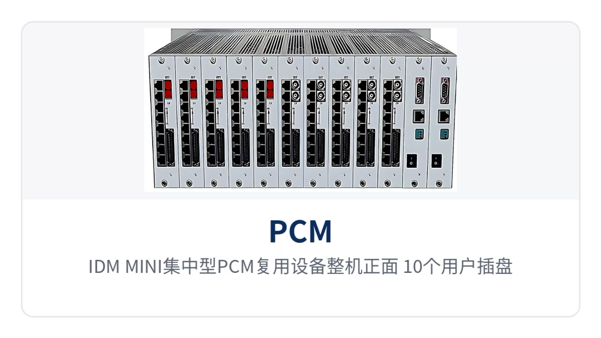
Figure 1: Front view of the IDM-MINI centralized PCM multiplexer, with 10 user card slots and line operation indicator LEDs
What is the 8+1-channel 64K centralized PCM multiplexer?
The 8+1-channel 64K centralized PCM multiplexer is an access device that multiplexes multiple types of narrowband services onto the same uplink channel. The 8 in the name refers to 8 channels of 64K voice or data, and the 1 refers to 1 channel of N×64K service. After entering the device, both service types are queued uniformly by 64K time slot and transmitted over the same E1 channel or optical fiber channel; at the opposite end they are restored to the original interfaces according to the same time slot allocation, with telephone, data and Ethernet each using their own time slots. As a mature PCM product showcase solution, the device plays the role of narrowband service aggregation in the integrated service access device lineup.
The difference between the centralized and single-board models lies in the chassis and slots. The IDM-MINI centralized model can be configured with 10 user card slots, and service capacity and interface types are determined by the card combination. When the site service list changes, cards can be swapped or added while the chassis and uplink channel remain unchanged; the single-board model fixes service interfaces within the board dimensions and suits edge sites with few service types and few points.
On the service side, the IDM-MINI centralized unit provides voice, V.24, V.35 and Ethernet interfaces; on the channel side, it provides E1 interfaces and optical fiber interfaces, with the two channel options selected according to on-site resources. After services are multiplexed onto one channel by the centralized unit, it can form chain networks, star networks and tree networks with other IDM series multiplexing equipment, and the networking approach adjusts as site distribution changes. As an optical multiplexer manufacturer, Ruiguang Jiyuan (Raytrans) provides complete selection support for the networking of optical multiplexing equipment and integrated service access devices.
What services can the PCM multiplexer carry: four interface types in one unit
The answer to what services the PCM multiplexer can carry depends on the installed service interface cards. The IDM-MINI 8+1-channel 64K centralized PCM multiplexer provides voice, low-speed data, synchronous data and Ethernet access within the same unit. The functions and descriptions are listed in the table below.
Function | Description |
|---|---|
Voice service access | Provides 8 channels of 64K voice channel access, with an audio range of 300 Hz to 3400 Hz and A-law compression encoding per ITU G.711, used for dispatch telephone and inter-site liaison |
Low-speed data access | V.24 interface with asynchronous transmission rate ≤9600 bps and synchronous 64 Kbps, electrical characteristics compliant with CCITT V.28, carrying low-speed asynchronous data or single-time-slot synchronous data |
Synchronous data access | V.35 interface with a transmission rate of n×64 Kbps and terminal interface compliant with ISO2593, used to carry N×64K synchronous data services |
Ethernet service access | Provides a 10Base-T Ethernet interface with standard protocol support for IEEE802.3, multiplexing site office data and collected data onto the same channel |
N×64K service access | Provides 1 N×64K service channel, occupying the corresponding number of 64K time slots as required by the service, transmitted in the same bundle as the 8 channels of 64K services |
E1 channel transmission | Converts various services into an E1 data stream, with a bit rate of 2048 Kbps and HDB3 line coding, compliant with ITU-T G.703, frame structure PCM30/31 |
Optical fiber channel transmission | The derivative model IDM-MINIO converts E1 transmission into optical fiber transmission, suitable for voice and data access over private network self-owned optical fiber line channels |
Line operation alarm | The panel provides a visual and audible alarm indication for line operation, alerting on-site duty personnel in both audible and visual ways when the link is abnormal |
Networking capability | Can coordinate networking with IDM series products to form integrated networks such as chain networks, star networks and tree networks, adapting to multi-site distribution |
Key specifications and interface standards
Parameters are divided into three parts: transmission channel, subscriber interface and power supply, listed item by item in the table below. Values are subject to the manufacturer's technical documentation and factory testing; the specific configuration of interface card combinations is subject to the accompanying technical documentation and commercial confirmation, and the card lists for sites in different industries can first be checked item by item by service type.
Item | Parameter/Specification | Description/Applicable Conditions |
|---|---|---|
E1 bit rate | 2048Kbps | Standard E1 line rate, compliant with ITU-T G.703 |
E1 line coding | HDB3 | Standard line coding, interfacing with existing 2M transmission equipment |
E1 frame structure | PCM30/31 | Primary group frame structure; services are carried in voice channel time slots |
E1 impedance | 75 Ω/120 Ω | Coaxial or balanced interface, selected according to the interfacing equipment |
Optical interface | FC (SC and others can be customized), single-mode with multi-mode optional | Interface form when using an optical fiber channel |
Optical transmission distance | Typically 20Km for single-mode | Can be extended with optional long-distance optical modules; the loss margin is calculated based on actual measurement with an optical power meter |
Subscriber plug-in board | Up to 10 in the centralized model | The services carried by each board correspond to those of the IDM-MINI board model |
Service interface card | More than 20 types, freely selectable | Configured in combination according to the on-site service list of voice, data and Ethernet services |
Ethernet interface | 10Base-T, IEEE802.3 compliant | Site office and collected data access |
Voice interface | Audio 300 Hz to 3400 Hz, A-law per ITU G.711 | Subscriber line interface for telephone voice channels |
V.24 interface | Asynchronous ≤9600bps; synchronous 64Kbps | Compliant with the CCITT V.28 protocol |
V.35 interface | n×64Kbps | Terminal interface compliant with ISO2593 |
Power supply mode | AC220V/DC-48V | Applicable to both mains-powered equipment rooms and sites with DC communication power supplies |
Overall power consumption | ≤50W | Overall value including service interface cards |
Operating temperature | 0℃~40℃ | Equipment room and temperature-controlled cabinet environments |
Relative humidity | ≤90% (non-condensing) | Normal operation under non-condensing conditions |
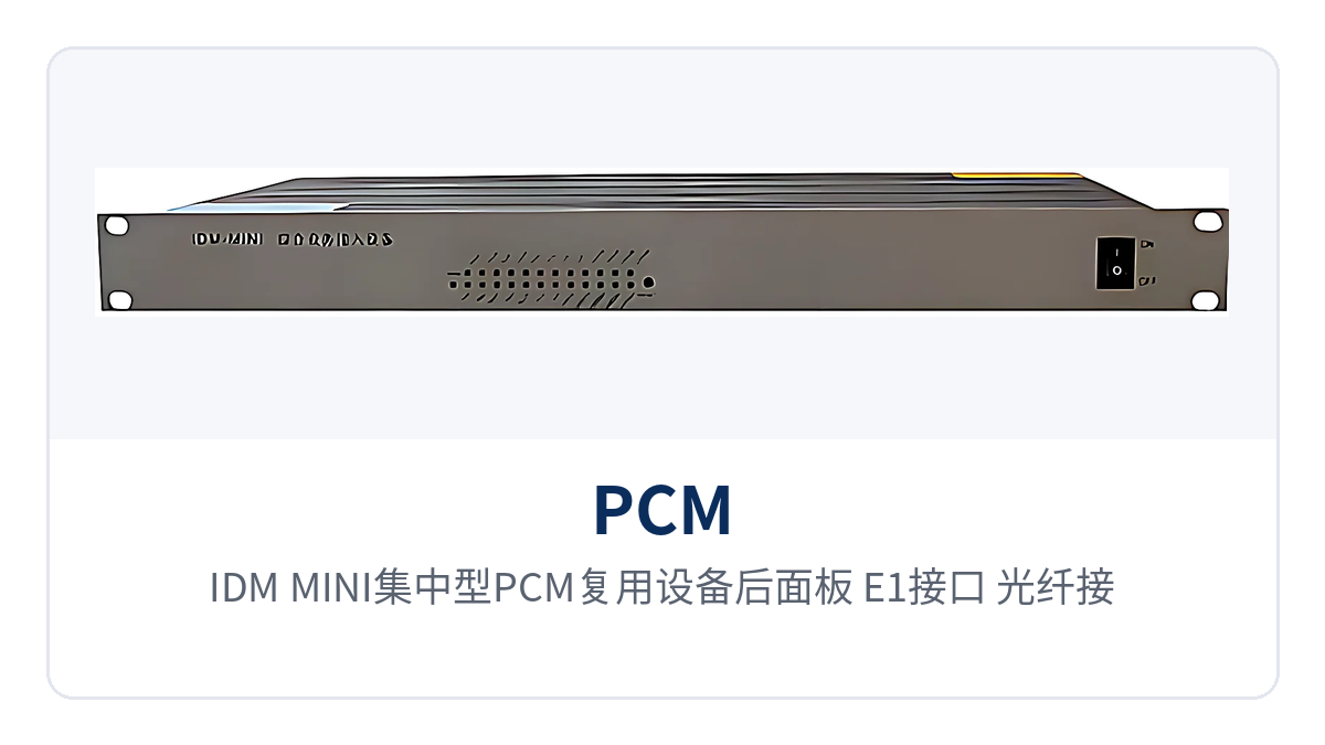
Figure 2: Rear panel of the IDM-MINI centralized PCM multiplexer, close-up of the E1 interfaces, optical fiber interfaces and AC/DC power supply terminals
How to choose between E1 and optical fiber channels: decide by on-site transmission resources
How to choose between E1 and optical fiber channels depends on which transmission resource already exists between sites. Sites with existing 2M dedicated lines, microwave or DDN channels use the E1 channel, extending the interface working distance without laying new optical cables; sites with their own optical fiber lines use the optical fiber channel, with services carried directly over the fiber and no additional optical-to-electrical conversion equipment required.
Both channels are built-in capabilities of the same model, with E1 transmission and optical transmission both available, so the two site conditions can be covered by the same centralized unit, and spare parts and O&M practices are unified accordingly. During selection, first confirm the site-side resources, then determine the interface cards and optical modules. The three common conditions are handled as follows:
Existing E1 digital trunk: connect to the E1 channel, with a 75 Ω or 120 Ω E1 interface, a bit rate of 2048Kbps and HDB3 line coding, directly connected to existing transmission equipment.
Own optical fiber lines: use the optical fiber channel and select the IDM-MINIO derivative model, extending voice and data services to the opposite end site over a single optical fiber, with no additional media converter needed in the equipment room.
Neither available: first confirm a rentable 2M dedicated line or microwave channel, configure the E1 channel, and keep only one centralized unit at the site side.
In government private network optical fiber communication solutions and military emergency communications vehicle solutions, the same channel selection logic applies; smart mining communication solutions can combine underground optical fiber resources and preferably use the optical multiplexing equipment form for site access.
How to configure more than 20 service interface cards: insert cards according to the service list
How to configure more than 20 service interface cards: first compile a complete site service list, then configure cards item by item according to interface type and number of channels. Configure voice channel cards by number of voice channels, data cards by V.24 or V.35 interface, and network cards by Ethernet interface, with card slots arranged across the 10 card slots of the centralized enclosure.
Cards are recommended to be configured in order of service importance: dispatch telephone and telecontrol data take slots first, followed by data channels interfacing with upper-level systems, and finally office and auxiliary services. Before inserting cards, check the correspondence between interface card models and board models; plug-in boards correspond one-to-one with the slot numbers of the enclosure, and cards are added to remaining slots during capacity expansion.
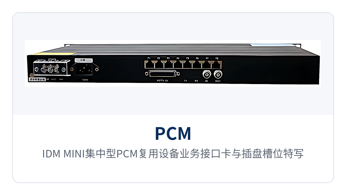
Figure 3: Close-up of the service interface cards and card slots of the IDM-MINI centralized PCM multiplexer, showing how more than 20 interface cards are inserted
After card insertion, verify channel by channel: go off-hook and listen on voice channels, run loopback tests on data ports, test Ethernet port connectivity, and confirm the front panel alarm LED and visual and audible alarm state together. When on-site service types change, simply replace cards according to the new list; the centralized enclosure and uplink channel remain unchanged, and the modification work stays at the plug-in board level. The product showcase materials provided by Raytrans describe the card combinations for each interface card item by item, and can serve as a reference for selection verification.
How to use visual and audible alarms on the centralized enclosure
Visual and audible alarms are built-in on-site diagnostic means of the centralized unit. The front panel provides visual and audible alarm indication for line operation; when abnormalities such as loss of signal or bit error alarms occur on a link, both audible and visual prompts are given simultaneously, so duty personnel can see status changes at the equipment room door without first connecting instruments for segment-by-segment troubleshooting.
Alarms are handled channel first, service second: first check the line indicator LED to confirm whether the E1 channel or optical fiber channel is normal, then check the service indicator LED corresponding to the plug-in board. Channel-side alarms mostly originate from the line, optical module or opposite end equipment, while service-side alarms are concentrated in interface cards and subscriber lines; by checking these two layers separately, the fault location scope is quickly narrowed. As an optical multiplexer manufacturer, Raytrans maintains a unified indication logic in the alarm design of PCM and optical multiplexing equipment, making it easy for O&M personnel to apply the same troubleshooting practices across sites.
Differentiated value: 8+1 channels of 64K, 20+ interface cards, E1/optical fiber options, visual and audible alarms
The differentiation of the IDM-MINI 8+1 channels of 64K centralized PCM multiplexer centers on four points: 8+1 channels of 64K, 20+ interface cards, E1/optical fiber options and visual and audible alarms. These four points are both equipment capabilities and corresponding engineering benefits for sites, as mapped item by item in the table below.
Differentiation Point | Specific Capability | Value to Private Network Customers |
|---|---|---|
8+1 channels of 64K | A single E1 or optical fiber channel carries 8 channels of 64K voice and data plus 1 channel of N×64K service at the same time, achieving high private network channel utilization | One 2M line or one pair of fiber cores carries all narrowband services of a site, reducing line rental and laying costs |
20+ interface cards | More than 20 types of service interface cards are available as options, so the same platform adapts to electric power, mining and expressway access scenarios | Sites in different industries share the same unit and spare parts, unifying engineering design and O&M practices |
E1/optical fiber optional | E1 and optical fiber transmission are both selectable; self-owned optical fiber lines directly extend service distance without additional conversion devices | Where 2M resources exist in the equipment room, use E1; where self-owned optical cable is available, go directly to fiber, so the two site types do not need separate device models |
Visual and audible alarm | The front panel provides visual and audible alarm indication for line operation, signaling abnormalities with both sound and light | At unattended sites, on-site instrument troubleshooting is reduced; duty personnel can judge channel and service status from the indicator LEDs |
Typical Application Scenarios
Centralized PCM multiplexing is deployed mainly in point-to-point and star topologies: one aggregation equipment is installed in the central equipment room and one centralized unit at each site. Site services are backhauled over E1 channels or optical fiber channels and restored at the central side, then connected to existing switching and transmission systems.
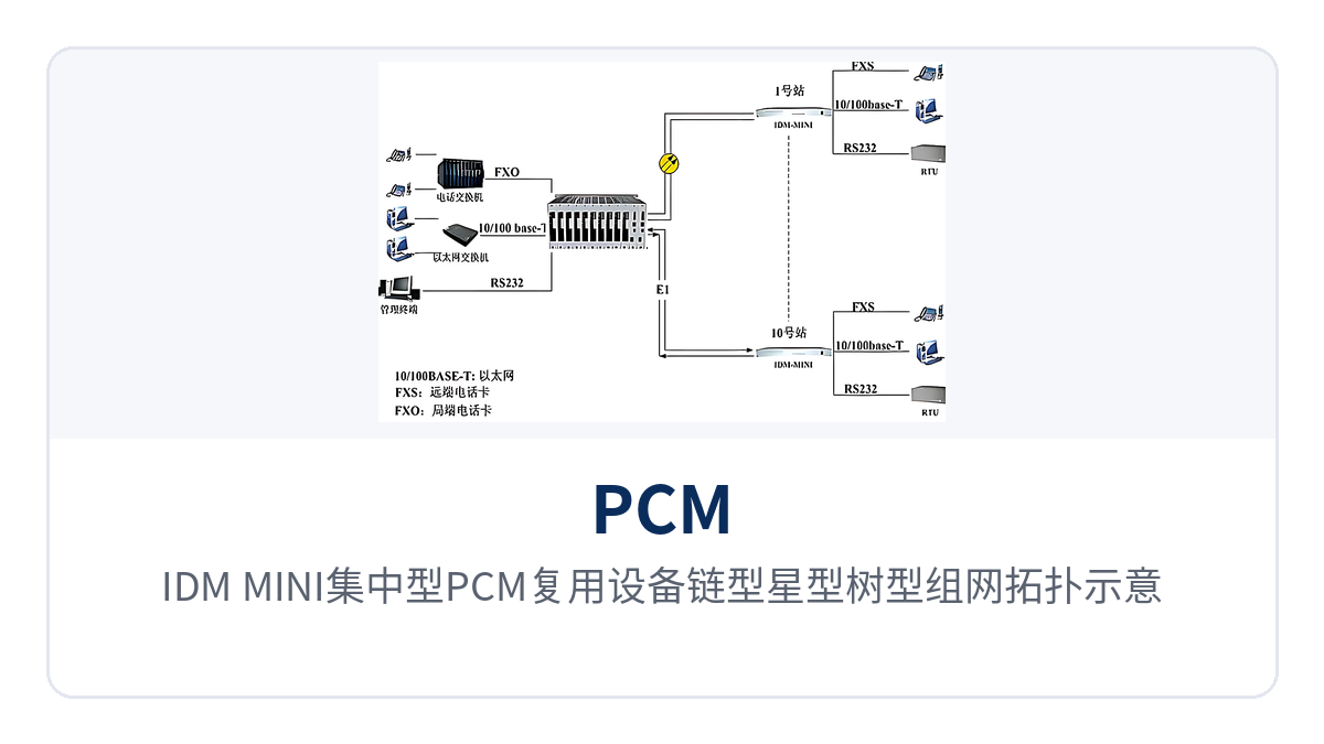
Figure 4: Schematic of chain, star and tree networking topology of IDM-MINI centralized PCM multiplexer, with central equipment room and multi-site access
Electric Power Private Network: Voice and Telecontrol Data Backhauled Together from Substation to Dispatch
Between substations, switching stations and the dispatch center of an electric power private network, both dispatch telephone and automated telecontrol data are carried. The IDM-MINI 8+1-channel 64K centralized PCM multiplexer accesses 8 voice channels and data interfaces at the station side, multiplexes voice and telecontrol data onto the same E1 channel for backhaul to the dispatch center, reducing the number of lines and providing a compact product showcase form for electric power scenarios beyond the government private network optical fiber communication solution.
The E1 interface has a bit rate of 2048Kbps and HDB3 line coding, complies with ITU-T G.703, and can be directly connected to existing 2M transmission equipment in the electric power private network, so the dispatch exchange at the opposite end requires no configuration change. When the site has its own optical cable, the service switches to the optical fiber channel and the service distance extends according to the optical module, while the number of devices and wiring in the equipment room is reduced accordingly.
Mining Communication: Voice and Data from Aboveground and Underground Sent Up over One Channel
In mining communication, dispatch telephone, environmental monitoring data and industrial Ethernet services are distributed among the pithead, underground substations and the dispatch room, where cable laying conditions are constrained. The IDM-MINI 8+1-channel 64K centralized PCM multiplexer accesses 8 voice and data interfaces at the underground site and multiplexes the services onto one E1 channel or one optical fiber for transmission up to the aboveground equipment room, reducing the number of cables and devices on the underground side; it is a practical choice for the edge access segment of a smart mining communication solution.
The 10 user plug-in boards are configured according to the underground service list, with telephone, V.24 monitoring data and Ethernet interfaces mixed in the same chassis; the visual and audible alarm on the front panel shows link status directly both underground and aboveground, reducing the number of trips underground for troubleshooting. The protection and power supply conditions of underground equipment are confirmed with the manufacturer according to on-site requirements, and the configuration is subject to the technical documentation supplied with the unit.
Expressway: Services Backhauled Nearby at Toll Stations and Service Areas
Between toll stations, service areas and roadside monitoring outfield of an expressway, toll service telephone, low-speed control data and office network need to be transmitted. The IDM-MINI 8+1-channel 64K centralized PCM multiplexer is installed as one centralized unit at the toll station, multiplexing the station's voice channels and data for backhaul to the road section center over existing 2M channels, standardizing service access at sites along the line.
Where the road section has its own optical cable, the optical fiber channel is used and services extend directly to service areas and outfield cabinets, without laying a separate optical multiplexer for each service type. More than 20 types of service interface cards are selected according to the site list, so toll, monitoring and office services are accessed on the same platform; later upgrades only require card replacement, without shutting down the entire channel.
Conclusion
The IDM-MINI 8+1-channel 64K centralized PCM multiplexer carries 8 channels of 64K voice and data plus 1 channel of N×64K service in one centralized unit, with E1 transmission and optical transmission selectable. The centralized chassis accommodates 10 user plug-in boards and more than 20 types of service interface cards as options, and the front panel provides visual and audible alarm indication for line operation. It suits edge access and service aggregation in electric power private networks, mining communication and expressways. As a centralized PCM product from Raytrans for private network access scenarios, this model can coordinate networking with integrated service access devices and optical multiplexing equipment, and often serves as the narrowband service aggregation unit in optical multiplexer manufacturer bundled solutions, serving typical deployments such as the government private network optical fiber communication solution, the military emergency communications vehicle solution and the smart mining communication solution.
During selection, first confirm the number of voice channels, data interfaces and Ethernet requirements according to the site service list, then check whether the uplink channel uses existing 2M trunks or self-owned optical fiber, and finally reserve room for capacity expansion based on the margin of the 10 card slots; once the card configuration list and the optical module distance grade are confirmed together, the unit configuration and quotation can be determined.