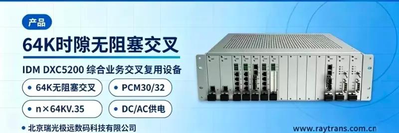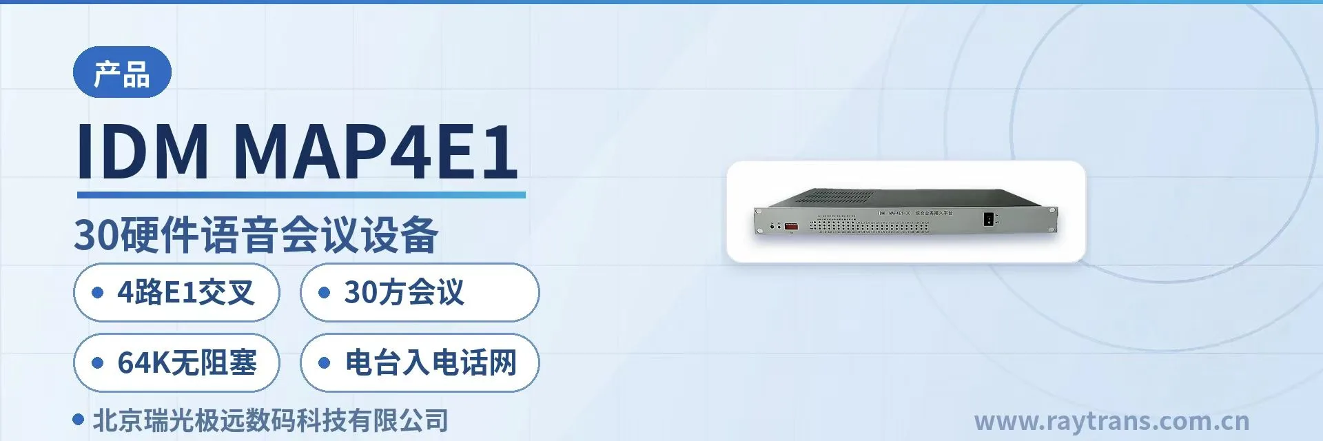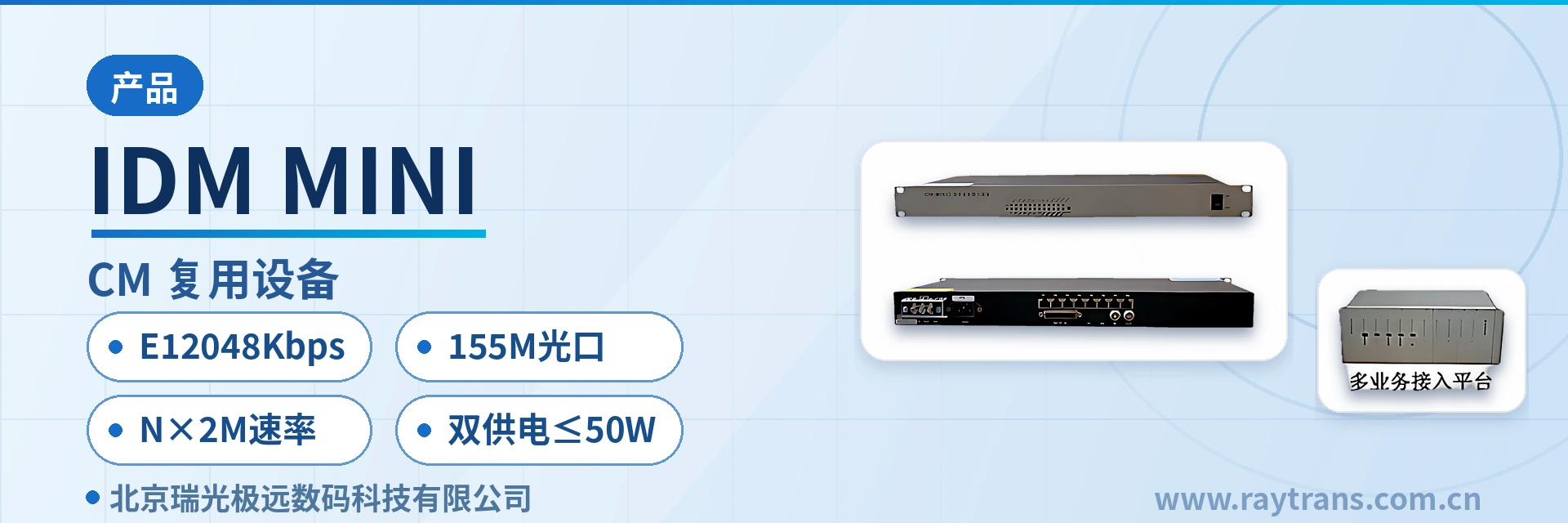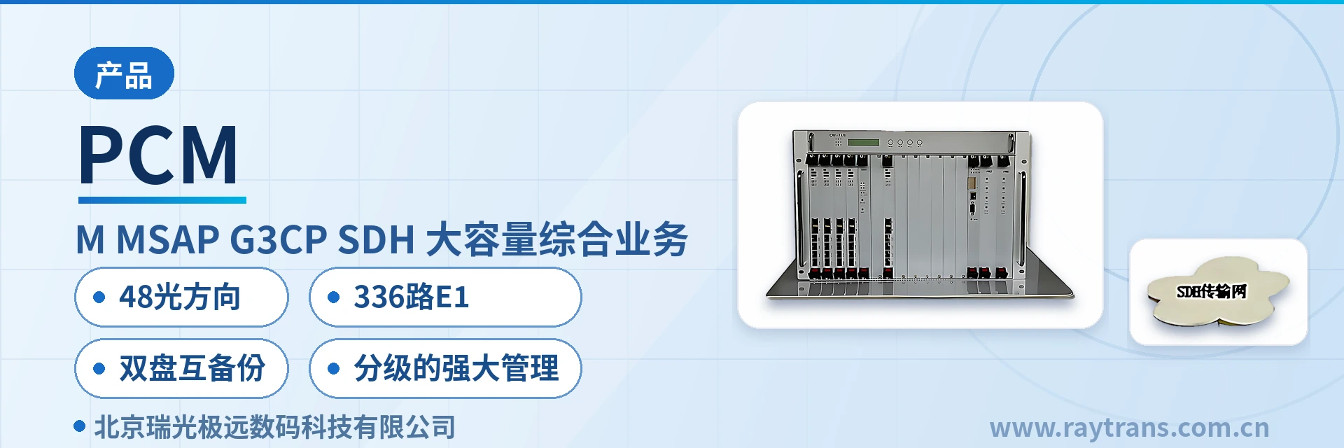
IDM-30E Integrated Service Multiplexer
30 channels multiplexed onto one E1, master/user clock, front-panel alarm indication
The IDM-30E integrated service multiplexer uses a standard 19-inch 1U chassis and provides 30 standard-defined subscriber interfaces. It supports AC 220 V or DC -48 V power supply.
The IDM-30E 30-channel subscriber interface integrated service multiplexer is a PCM equipment that multiplexes 30 channels of 64K subscriber service onto an E1 digital trunk for transmission. Developed by Beijing Ruiguang Jiyuan Digital Technology Co., Ltd., it is used for voice and data service extension between a central office switch and remote subscribers. As a typical PCM equipment, it is often classified under integrated service access devices in product showcases, and together with optical multiplexing equipment and the optical multiplexer manufacturer's product series, it forms a complete access solution.
What is an integrated service multiplexer? In one sentence, it multiplexes the spare E1 digital trunk ports or analog subscriber interface resources of a central office switch into 30 subscriber interfaces that remote sites can access directly, replacing exchange subscriber line provisioning for remote small offices. Remote stations therefore do not need to build a separate switching office; voice and data services can be extended to each subscriber area, and equipment room space and construction costs are reduced accordingly. With such integrated service access devices, Raytrans can provide reliable remote access support for government private network optical fiber communication solutions, military emergency communications vehicle solutions, and smart mining communication solutions.
The IDM-30E 30-channel subscriber interface integrated service multiplexer uses coaxial cable as the transmission medium to complete the above connections. It adopts a standard 19-inch 1U chassis and provides 30 standard-defined subscriber interfaces, so a single unit can meet the dense access requirements of small and medium-sized sites. The device supports either AC 220 V or DC -48 V power supply; both AC mains power in the equipment room and the station's DC distribution panel can be connected directly, with no additional conversion equipment required.
Key Specifications at a Glance: 30 subscriber interfaces · 1U standard chassis · dual power supply options · front-panel alarm indication · E1 2048 kbit/s · overall power consumption 20 W ±10%
Figure 1: Front view of the IDM-30E 19-inch 1U unit and power indicator LED
What the 30-channel subscriber interface integrated service multiplexer is
The IDM-30E 30-channel subscriber interface integrated service multiplexer consists structurally of three parts: the chassis, service interface cards, and the power supply. The front panel houses the function control switch and alarm indicator LEDs, while the rear panel provides the E1 interface, subscriber interfaces, and power supply terminals. As a PCM equipment designed for private network scenarios, the unit completes service access and multiplexing within a 1U chassis, making it easy to deploy alongside other integrated service access devices in the same equipment room cabinet.
The clock mode can be set to master clock or user clock. Use the user clock when synchronizing to the central office switch, and the master clock when the local end derives the clock from the service side. The two modes cover common networking conditions in electric power, rail transit, and private network equipment rooms. Select the mode on site according to whether the opposite end provides a clock reference; only one side of a link provides the clock.
The function control switch and alarm indicator LEDs on the panel are the entry point for on-site troubleshooting. When an optical port or E1 interface fails, the corresponding alarm indicator LED lights up, so O&M personnel can determine at the cabinet whether the problem is the link or the service card. Combined with the equipment room's environmental monitoring alarms, the fault alarm indication allows problems at unattended sites to surface promptly between two inspection rounds, reducing the situation where a fault waits for the next inspection. The emergency repair team can narrow the scope to the link or the service card before setting out. For remote nodes in government private network optical fiber communication solutions and military emergency communications vehicle solutions, this front-panel alarm indication likewise shortens fault location time.
Figure 2: Close-up of the IDM-30E front-panel function control switch and E1 alarm indicator LED
Features
The functions of the IDM-30E 30-channel subscriber interface integrated service multiplexer cover four categories: service access, clock synchronization, alarm monitoring, and power supply. The specific role and on-site use of each function item are listed in the table below, making it easy to check the configuration against site conditions and allocate service cards by interface type.
| Function | Description |
|---|---|
| 30-channel 64K service access | Provides 30 standard-defined subscriber interfaces; voice and 64K data services are configured according to site requirements |
| E1 digital trunk access | Connects to the E1 digital trunk port of the central office switch and multiplexes 30 channels of service onto one E1 link for transmission |
| Master/user clock mode | Can be set to master clock or user clock to suit networking conditions where the clock is synchronized to the central office or derived from the service side |
| FXO/FXS telephone interfaces | Provides ordinary telephone cards with caller ID, supporting both central office side and user side access directions |
| Panel alarm indication | When an optical port or E1 interface fails, the corresponding alarm indicator LED lights up, allowing link status to be identified at the cabinet |
| Function control switch | The front panel provides a function control switch for on-site switching of operating modes and verification of the current running configuration |
| Dual power supply options | Supports AC 220 V or DC -48 V power supply; AC equipment rooms and DC power supply scenarios are configured according to on-site conditions |
| Coaxial cable transmission | Uses coaxial cable as the transmission medium to connect subscriber terminals to each other or to the public switched telephone network (PSTN) |
Figure 3: IDM-30E 30-channel subscriber interface service card slots and rear-panel cable routing
Key Specifications
The key specifications are divided into three groups: E1 interface, FXO/FXS interface, and power supply and the unit. The figures are taken from the original product documentation. Checking these three groups item by item during selection and construction briefing helps avoid ordering after checking only the link rate and discovering after installation that the impedance or power supply does not match.
E1 Interface Specifications
| Item | Parameter/Specification | Description/Applicable Conditions |
|---|---|---|
| Standard protocol | Fully compliant with ITU-T G.703 | Connects to the E1 ports of central office switches, SDH or PDH equipment under the same recommendation |
| Line coding | HDB3 | Base group line coding; long-distance links are designed according to regenerator section (RS) and line loss |
| Bit rate | 2048 kbit/s ±50 ppm | The E1 2048 kbit/s basic rate; a frequency offset within ±50 ppm is compatible with the opposite end's clock |
| Impedance | 75 Ω (unbalanced) / 120 Ω (balanced) | An external impedance converter is required when using the 120 Ω balanced interface |
| Frame structure | PCM30/32 | Standard base group frame with 30 voice channels plus synchronization and signaling time slots |
| Signaling | Channel-associated signaling (CAS) | Voice channel signaling is transmitted together with voice, with no separate signaling link required |
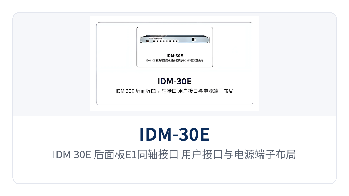
Figure 4: IDM-30E rear-panel layout of E1 coaxial interfaces, subscriber interfaces, and power supply terminals
FXO/FXS Interface Specifications
| Item | Parameter/Specification | Description/Applicable Conditions |
|---|---|---|
| Impedance | Three-element complex impedance 200 Ω + 560 Ω // 0.1 μF | Matches ordinary telephones and analog subscriber ports of switches |
| Audio range | 300 Hz to 3400 Hz | Voice frequency band, covering the call and fax requirements of ordinary telephones |
| Compression | ITU G.711 A-law | Standard 64 kbit/s voice encoding, consistent with the encoding used in domestic telephone networks |
| Loop current | 25 mA per channel | Power feeding current, ensuring stable telephone ringing and calls |
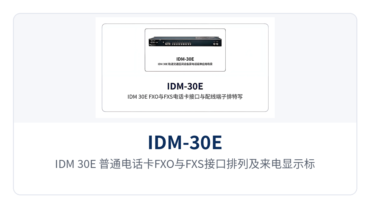
Figure 5: IDM-30E ordinary telephone card FXO and FXS interface arrangement and caller ID marking
Power Supply and the Unit
| Item | Parameter/Specification | Description/Applicable Conditions |
|---|---|---|
| Chassis structure | 19-inch 1U standard chassis | Standard rack installation, compatible with conventional communications cabinets and station panels |
| Number of subscriber interfaces | 30 (standard-defined) | A single unit meets dense access at small and medium-sized sites; plan capacity expansion by interface positions |
| Power supply mode | AC 220 V or DC -48 V | AC and DC power supply scenarios in the equipment room are configured on site; confirm at ordering |
| Overall power consumption | 20 W ±10% | Reserve cabinet power capacity and heat dissipation margin based on the nominal value |
| Transmission medium | Coaxial cable | User-side transmission medium; verify separately from the cable specification of the E1 link |
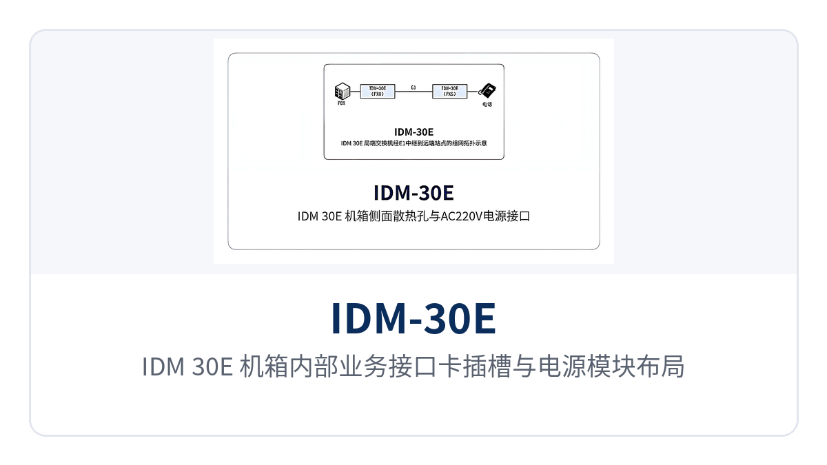
Figure 6: IDM-30E internal service interface card slots and power supply module layout
How the three capabilities apply on site
The value of the IDM-30E 30-channel subscriber interface integrated service multiplexer centers on three aspects: access density, power supply adaptability, and on-site maintainability. Comparing each against site conditions is enough to judge whether the configuration is appropriate. The table below lists the three capabilities alongside their on-site benefits; check row by row during selection briefing rather than going through the parameter table item by item.
| Differentiated capability | Value to users |
|---|---|
| A single 1U unit provides 30 subscriber interfaces | One 1U device replaces exchange subscriber line provisioning at a remote small office; 30 voice and 64K data channels are allocated according to site requirements, and equipment room space and switching equipment construction costs decrease accordingly |
| Dual power supply options | AC 220 V and DC -48 V are ordered according to on-site conditions; both electric power DC distribution panels and AC mains power at vehicle-mounted and temporary sites can be connected directly, eliminating extra conversion stages |
| Front-panel alarm indication and control switch | When an optical port or E1 interface fails, the alarm indicator LED lights up, and the operating mode can be verified on the panel; unattended sites can complete fault location at the cabinet |
In smart mining communication solutions, the service aggregation points underground and above ground often have limited space and varying power supply conditions; this device adapts to such sites with its 1U chassis and dual power supply options. In government private network optical fiber communication solutions and military emergency communications vehicle solutions, it can serve as the service termination unit between PCM equipment and optical multiplexing equipment. As an optical multiplexer manufacturer, Raytrans provides selection support for such integrated service access devices, from product showcase to networking configuration, making it easy for users to verify and deploy equipment according to site conditions.
Typical Application Scenarios
As a mature PCM equipment, the IDM-30E 30-channel subscriber interface integrated service multiplexer targets electric power private networks, rail transit, and military and government private networks. What these three scenarios have in common is extending the switching capability of the central office to sites that are far away and carry low traffic but must retain voice service, replacing a small switching office with one 1U integrated service access device.
Electric power private networks: voice and telecontrol services at substations and power supply stations
Substations and power supply stations in electric power private networks usually do not have an independent switching office. The IDM-30E 30-channel subscriber interface integrated service multiplexer extends dispatch telephones and office telephones to the station over an E1 digital trunk, while also carrying 64K telecontrol and data services, eliminating the work of laying separate subscriber lines.
The 19-inch 1U chassis can be installed directly in the station's communications cabinet, and the DC -48 V power supply matches the station's DC power distribution panel, with no additional AC conversion stage required. The panel alarm indicator LED lights up when the link is interrupted, so on-site alarms at unattended substations and monitoring at the centralized control center can corroborate each other, and repair personnel can determine the fault scope before arriving.
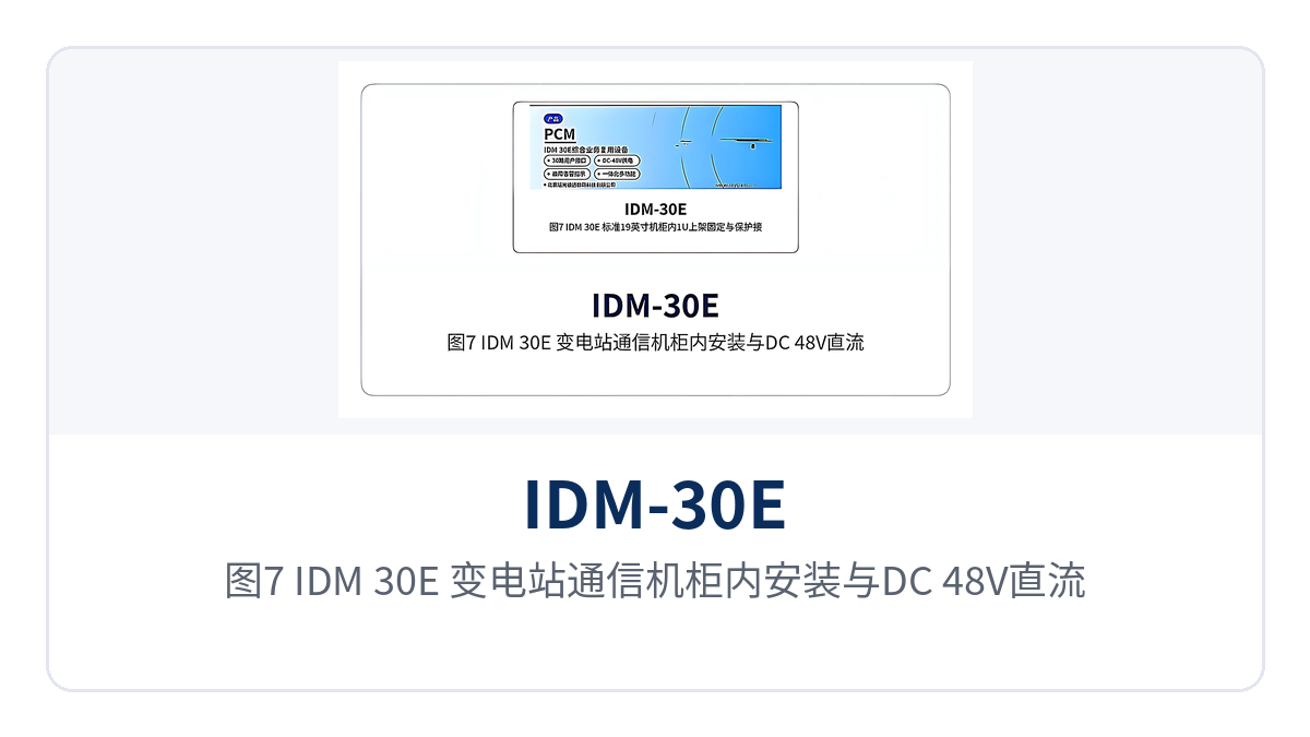
Figure 7: IDM-30E installed in a substation communications cabinet with DC -48 V power distribution panel wiring
Rail transit: telephone extension at stations along the line and section equipment rooms
Stations along the rail transit line, traction substations, and section equipment rooms are scattered, so installing switching equipment at every point is neither economical nor easy to maintain uniformly. The IDM-30E 30-channel subscriber interface integrated service multiplexer uses the E1 resources of existing transmission channels to connect train dispatching telephones and service telephones in equipment rooms into the same switching system.
The 30 subscriber interfaces are allocated according to the number of telephones at each point, and the remaining interface positions between sites can be reserved for subsequent upgrades and temporary power supply. After the equipment is rack-mounted, acceptance is carried out against the three items of "LED, number, and voice," and the O&M team can complete the activation of new sites with the same process, without writing a separate commissioning plan for each type of site.
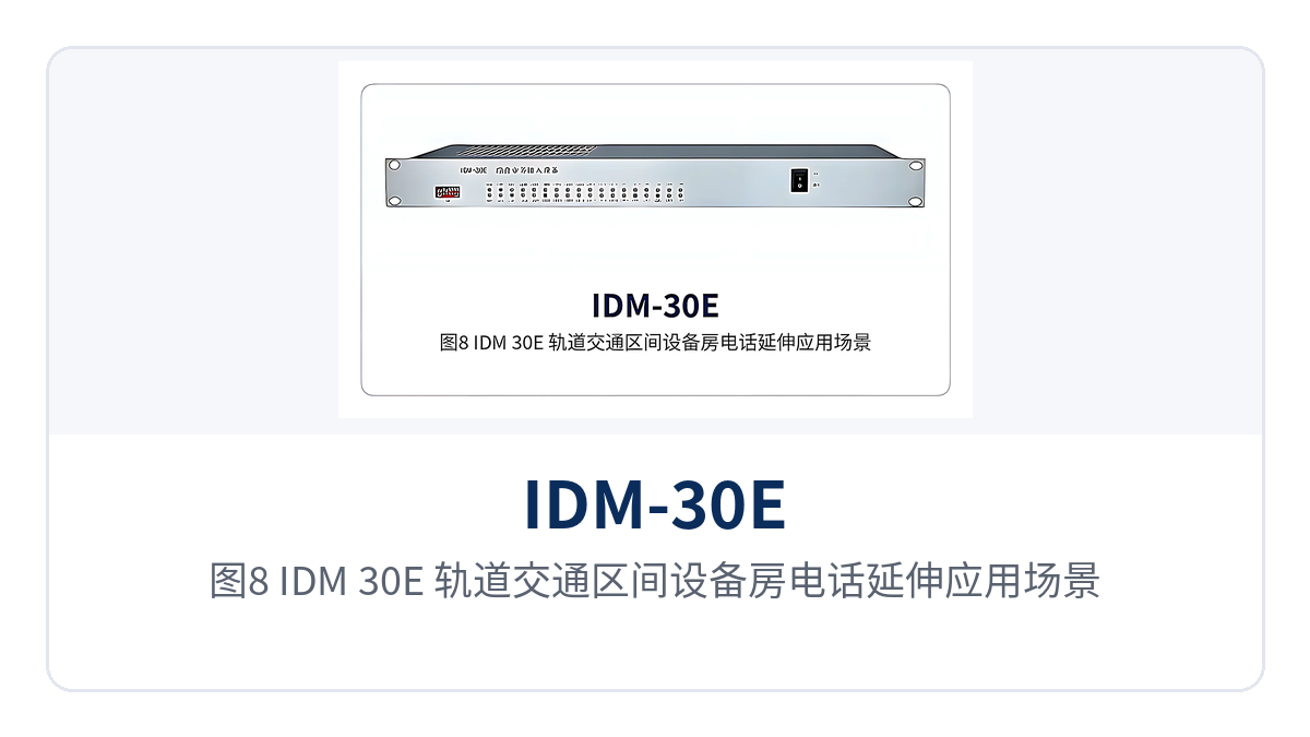
Figure 8: IDM-30E telephone extension application scenario in a rail transit section equipment room
Military and Government Private Networks: Remote Subscriber Line Provisioning and Temporary Command Post Access
Remote subscriber line provisioning points on military and government private networks often have no fixed equipment room, and power supply conditions are not uniform, with both AC mains power and -48 V DC encountered on site. The IDM-30E 30-channel subscriber interface integrated service multiplexer offers two options, AC 220 V power supply or DC -48 V power supply, ordered according to on-site power conditions; once rack-mounted, the telephones at command posts, duty rooms, and duty posts can be connected to the private network switching system.
The 30 subscriber interfaces are fully equipped in a single unit, so when a temporary command post is withdrawn, the complete unit is taken along and services migrate with the equipment, with no need to re-arrange interface cards at the new point. The panel alarm indication and function control switch are concentrated on the front panel, and takeover personnel can complete routine inspection according to the panel status.
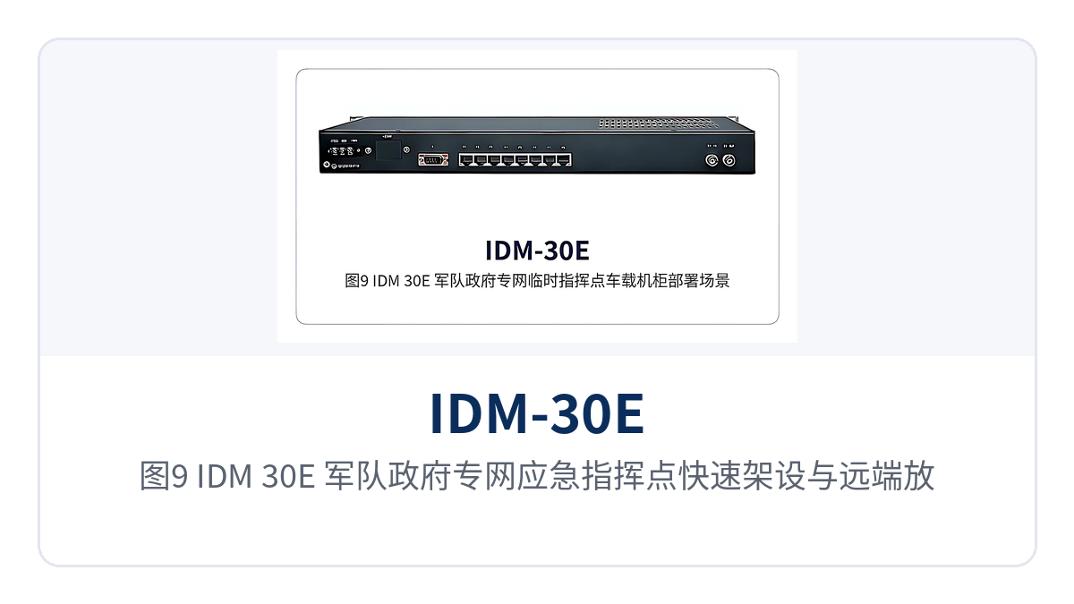
Figure 9: IDM-30E rapid setup and remote subscriber line provisioning scenario for an emergency command post on a military and government private network
How Does PCM Equipment Connect to an E1 Digital Trunk
How PCM equipment connects to an E1 digital trunk is advanced on site in four steps: check central office trunk resources, determine impedance and cables, set the clock, and perform dial test acceptance. Each step corresponds to verifiable items; skipping a step often means rework only at the commissioning stage, which thins the margin left for the commissioning window.
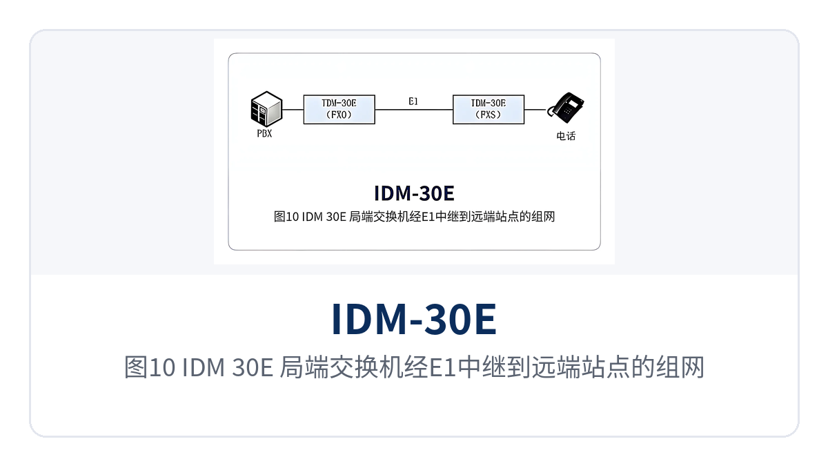
Figure 10: IDM-30E networking topology schematic from the central office switch to a remote station over an E1 trunk
- Check central office resources: record the number, frame structure, and signaling mode of the E1 digital trunk port on the switch side, and confirm consistency with PCM30/32 and channel-associated signaling (CAS), so as to avoid discovering that the trunk port has not been provisioned only after the board is plugged in.
- Determine impedance and cables: use coaxial cable and BNC connectors for the 75 Ω unbalanced interface; for the 120 Ω balanced interface, an external impedance converter is required before connection; handle the shielding layer according to equipment room grounding practices.
- Set the clock: set the user clock when synchronizing with the central office switch, and set the master clock when the clock is taken from the local service side; only one side of a link provides the clock.
- Dial test acceptance: after power-on, check whether the E1 alarm indicator LED is off, then dial each channel and verify caller ID (CID), voice quality, and time slot mapping.
After wiring is complete, acceptance is carried out against the three items of "LED, number, and voice": the E1 alarm LED being off indicates the link is synchronized, dialing each channel indicates signaling and time slot mapping are correct, and listening tests indicate audio and feeding are normal. When some channels fail, first check the time slot allocation table, then check the corresponding subscriber card and telephone; this locates faults faster than removing the complete unit for re-inspection.
Figure 11: IDM-30E E1 coaxial cable BNC connector connection and loopback test with a bit error rate tester
How Are FXO and FXS Allocated Among the 30 Subscriber Interfaces
How FXO and FXS are allocated among the 30 subscriber interfaces depends on which side the service is taken from: use FXO toward the analog subscriber port of the switch, and FXS toward ordinary telephones. The two types of cards can be mixed within the 30 interfaces according to the actual call handling at the site; before ordering, count how many telephones and external trunks exist at each end.
- FXO interface (central office side): connects to the analog subscriber port of the switch, equivalent to registering remote telephones on the central office switch; suitable for subscriber line provisioning at remote offices and duty rooms.
- FXS interface (user side): directly connects ordinary telephones or fax machines, with the equipment providing feeding and ringing; suitable for fixed telephones in substations and equipment rooms.
- Mixed configuration: when a site has both internal telephones and external subscriber line provisioning needs, allocate the two types of cards according to the number of telephones and the number of trunks, and reserve the remaining interface positions for capacity expansion.
- Caller ID: both types of ordinary telephone cards support caller ID, and the calling party number is displayed on the telephone according to the number delivery mode of the central office.
How to Rack-Mount a 1U Rack-Mounted PCM Device
How to rack-mount a 1U rack-mounted PCM device is completed in four items: cabinet position, rack mounting and fixing, power and grounding, and alarm verification. The 19-inch 1U chassis occupies only 1U in height, with weight concentrated on the power supply and interface card side; when rack-mounting, leave space at the front and rear for cabling and heat dissipation.
- Determine the cabinet position: select the cabinet according to the routing of E1 cables and subscriber lines, leave operating space at the front panel, and leave bending radius for coaxial connectors and subscriber lines at the rear panel.
- Rack mounting and fixing: fix to the cabinet posts with standard 19-inch mounting brackets, with no fewer than two screws on each side, to avoid panel deformation from hanging on only one side.
- Connect power and grounding: connect according to the ordered AC 220 V or DC -48 V supply, observe polarity for DC power supply, and route the chassis protective grounding separately to the cabinet grounding bar.
- Verify alarms: after power-on, confirm the power indicator is steadily on and the E1 alarm LED status is normal, then verify the current operating mode and configuration against the function control switch.
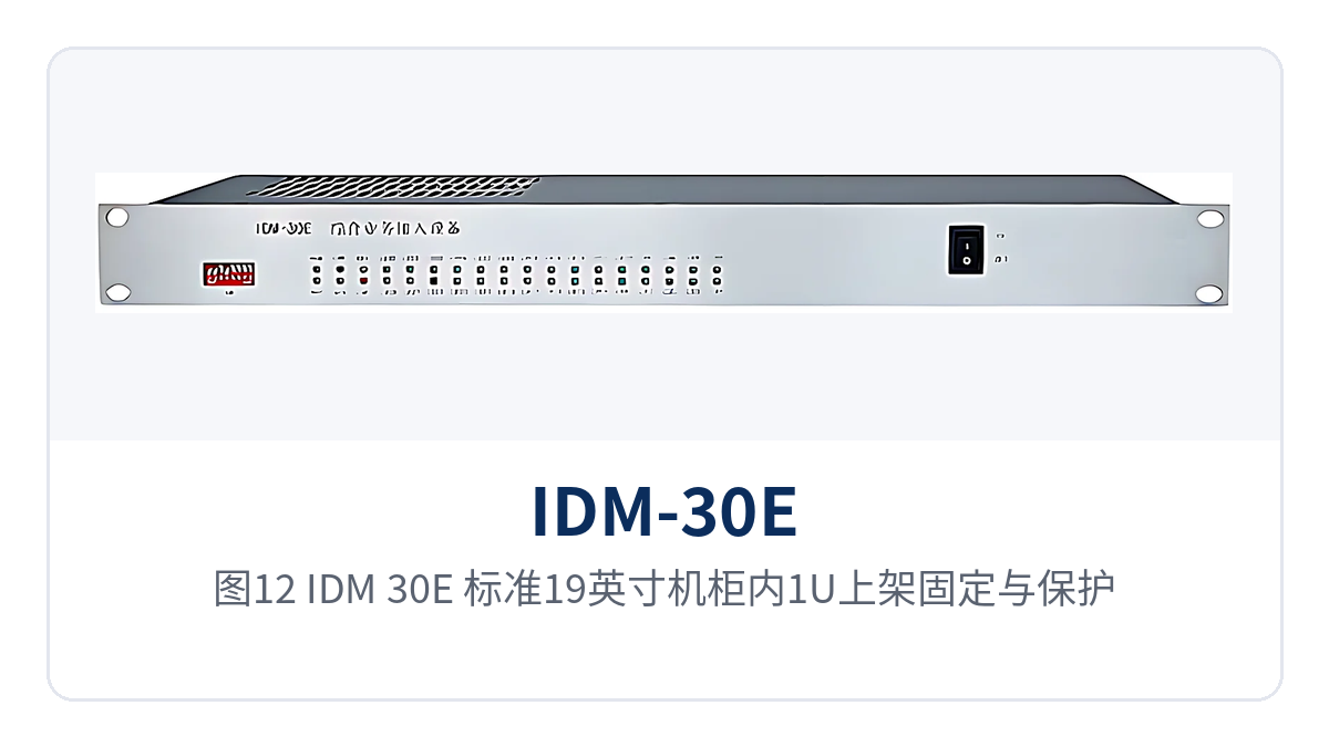
Figure 12: IDM-30E 1U rack mounting and protective grounding in a standard 19-inch cabinet
The fit between the mounting brackets and the posts determines whether the panel is stressed evenly; if even one screw is missing on either side, the front panel is prone to deformation and poor contact when subscriber lines are plugged or unplugged. Before rack-mounting, leave the 1U spaces above and below the cabinet empty as well, so that heat dissipation and cabling are easier.
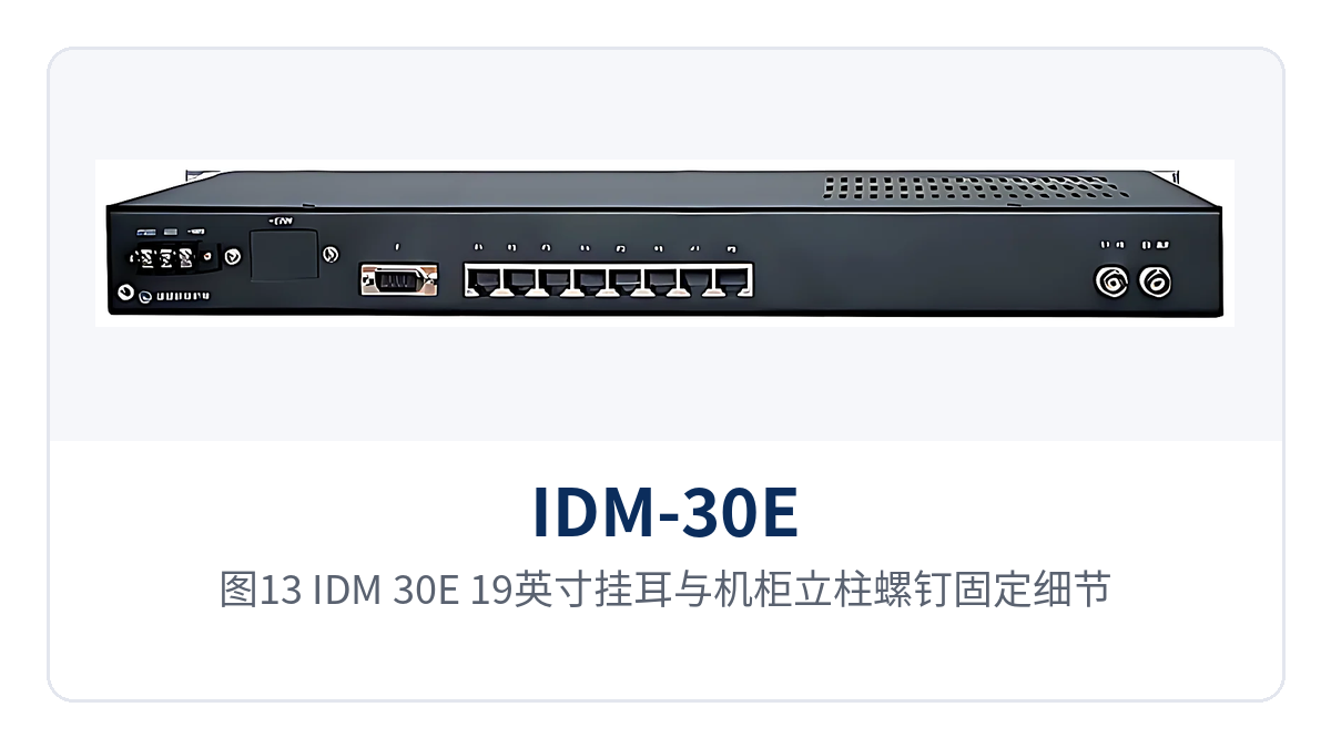
Figure 13: IDM-30E 19-inch mounting bracket and cabinet post screw fixing details
The heat dissipation vents on the side of the chassis continuously exhaust heat after power-on, so air must flow between the front and rear panels, and cabinet doors and cable managers must not block the vents. When the AC 220 V model draws power inside the cabinet, route the power cable separately from the E1 coaxial cable to reduce power-frequency interference.
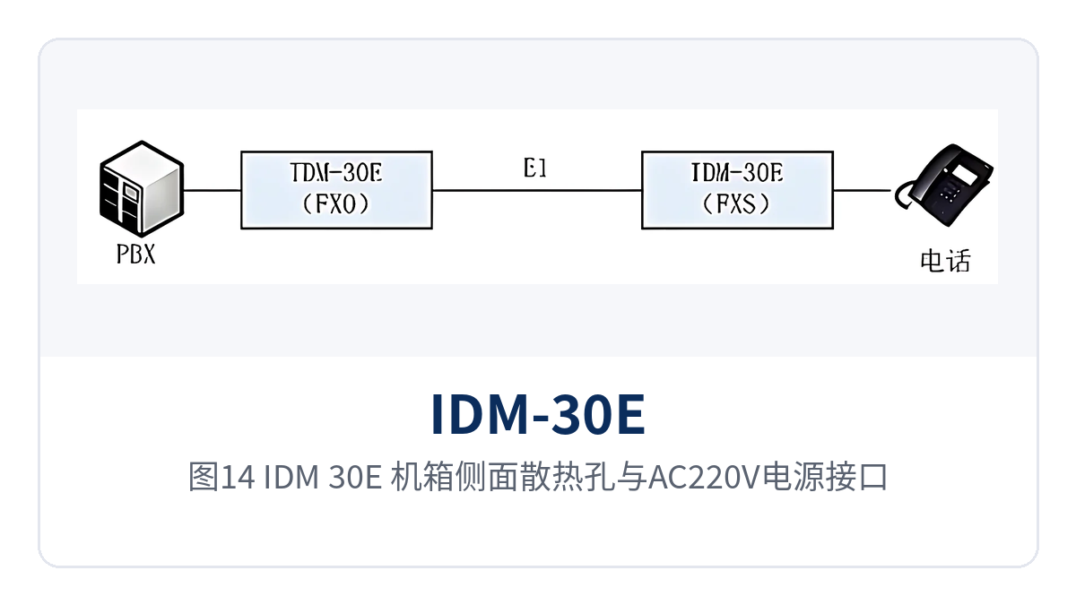
Figure 14: IDM-30E chassis side heat dissipation vents and AC 220 V power connector
Conclusion
The IDM-30E 30-channel subscriber interface integrated service multiplexer collects 30 channels of 64 kbit/s service into a 19-inch 1U chassis and connects to private network trunks over 2048 kbit/s E1 links, making remote subscriber line provisioning and service extension a routine project deliverable with a single rack mounting. As an integrated service access device and optical multiplexing equipment, it presents a compact and easy-to-maintain profile in the product showcase, and Raytrans PCM equipment has therefore found practical application in government private network optical fiber communication solutions, military emergency communications vehicle solutions, and smart mining communication solutions.
For selection, determine the configuration by three items: number of subscriber interfaces, FXO/FXS ratio, and power supply mode; during installation, carry out acceptance in the three steps of LED, number, and voice. Remote sites in electric power, rail transit, and government private networks can all be implemented with the same process, and subsequent capacity expansion follows the same spare parts and operating habits.