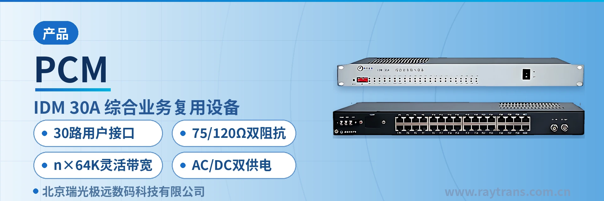
PCM Equipment IDM-30A Integrated Service Multiplexer
30 64K time slot cards mixed in one chassis, supports over 20 service card types, card replacement without replacing the whole unit
The IDM-30A Integrated Service Multiplexer uses a standard 19-inch 1U chassis; provides 30 standard-defined subscriber interfaces; offers abundant 64K subscriber interfaces and supports flexible configuration of over 20 interface card types; can be configured with n×64K V.35/V.11 or Ethernet subscriber interfaces;
The 30-channel card-based PCM multiplexer is a multiplexing device that packs 30 channels of 64K subscriber services into a single 19-inch 1U chassis and delivers them to the opposite end over an E1 channel. The IDM-30A integrated service multiplexer is developed by Beijing Ruiguang Jiyuan Digital Technology Co., Ltd. (Raytrans). As a typical integrated service access device, it is used for edge access and leased line extension in electric power, rail transit, military and government private networks, and is also often used for access layer solution demonstrations in product showcase scenarios.
The device adopts a card-based design. A standalone unit provides 30 standard-defined subscriber interfaces, and the 64K subscriber interfaces can be configured with more than 20 types of interface cards. Voice, audio, data and Ethernet cards can be mixed in the same chassis; for each interface type in the site service list, one corresponding card is installed.
Services at private network edge sites are usually mixed: a substation or station needs dispatch telephones as well as low-speed data such as telecontrol and monitoring, and may also carry one Ethernet channel for a business system. The IDM-30A maps these services uniformly into the 30 64K time slots of the PCM30/31 frame structure, and sends them out on the E1 side at 2048Kbps with HDB3 line coding in accordance with ITU-T G.703. With this PCM time slot mapping approach, Raytrans's government private network optical fiber communication solution, military emergency communications vehicle solution, electric power private network edge access solution and rail transit private network access solution can all be deployed quickly at edge sites.
Once the opposite end receives the stream and restores it to the corresponding voice or data interfaces, the service can be enabled, and existing transmission equipment does not need to be changed. When the service types at a site change, replacing interface cards is easier than replacing the whole unit, the cabling in the cabinet does not need to be re-arranged, and the commissioning period is shortened accordingly.
Key Specifications at a Glance: 30 subscriber interfaces · more than 20 interface cards · E1 2048Kbps/HDB3 · 75/120 Ω dual impedance · flexible n×64K bandwidth · AC/DC dual power supply
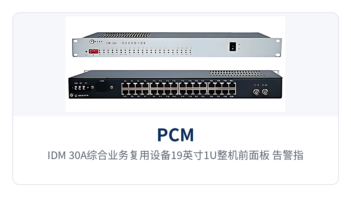
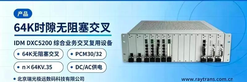
Figure 1: Close-up of the front panel, alarm indicator LEDs and interface card slots of the IDM-30A integrated service multiplexer 19-inch 1U unit
What is a 30-channel card-based PCM multiplexer?
The architecture of the 30-channel card-based PCM multiplexer has three layers: the chassis and power supply are fixed, the E1 uplink channel is fixed, and all customer-side services are carried by interface cards. The chassis, power supply and E1 uplink section are integrated at the factory, and the device runs once a 2M channel is connected; whatever card is installed on the customer side determines which interfaces are provided. Changing a card does not change the chassis or the uplink, which is exactly the practical value of the card-based design at private network edge sites, and also gives PCM equipment such as Raytrans's flexible interface adaptation capability in edge access scenarios.
Service deployment is time slot based. The E1 side transmits at the 2048Kbps primary rate with a PCM30/31 frame structure, and all 30 64K time slots are available for services; the number of time slots occupied by each interface card depends on the card type — a voice channel card occupies 1 time slot, while n×64K data cards and Ethernet cards occupy n time slots. Time slot allocation and card type combinations are determined in the factory configuration, and on site it is sufficient to connect cables according to the panel and cable markings. This time slot based bearer approach enables PCM equipment to support the product showcase requirements of multiple services such as voice, data and Ethernet at the same time.
The panel provides a function control switch and alarm indication, so channel status can be checked on site during commissioning; the device also provides network management functions for online real-time monitoring of operating status. For unattended edge sites, panel indication and network management work together, so routine inspection does not require opening each site for checks.
Which service interfaces and functions can one 1U device provide?
The functions of the IDM-30A can be viewed from four aspects: uplink channel, customer-side interfaces, O&M methods and power supply mode. The eight main capabilities are listed one by one in the table below. When checking against the project list, first select the interface cards by service type, then verify whether the remaining items meet on-site conditions.
Function | Description |
|---|---|
30 subscriber interfaces | Provides 30 standard-defined subscriber interfaces in a 19-inch 1U chassis, corresponding to the 30 64K time slots of the PCM30/31 frame structure |
More than 20 interface cards, freely configurable | 64K subscriber interfaces are implemented as interface cards, and the same chassis can be equipped with voice, audio, data, Ethernet and other card types according to site services |
E1 uplink channel | Bit rate 2048Kbps, line coding HDB3, ITU-T G.703 compliant, 75 Ω/120 Ω selectable impedance, channel-associated signaling (CAS) |
n×64K data interface | Configurable n×64Kbps V.35/V.11 subscriber interfaces, with rates allocated from the time slot pool as required by services |
Ethernet subscriber interface | RJ-45 interface, transmission rate n×64Kbps (n≤30), IEEE802.3 compliant, full/half duplex/adaptive |
Panel control and alarm indication | The panel provides a function control switch and alarm indicator LEDs for commissioning, channel verification and fault location |
Online network management monitoring | Provides network management functions for online real-time monitoring of device operating status, reducing on-site inspection trips |
AC/DC dual power supply | Power supply mode AC220V or DC-48V, overall power consumption ≤50W, installable in both AC equipment rooms and communications DC distribution panels |
What must be decided first in the table is the interface card combination: whether the 30 subscriber interfaces become voice channels or data after cards are installed depends on which card types are installed. The remaining items are fixed by model before delivery and only need to be checked once during selection. Aligning the card type list with the site service list item by item prevents insufficient interfaces or mismatched card types during commissioning. As an integrated service access device, the IDM-30A supports the product showcase of services through mixed installation of multiple card types, covering the edge access requirements of scenarios such as the government private network optical fiber communication solution and the electric power private network edge access solution.
Technical Specifications and Interface Standards
E1 Uplink Interface and Ethernet Interface Parameters
The parameter definitions of the E1 uplink and Ethernet sections determine whether the device can interconnect with existing on-site transmission channels. The table below lists them in three columns: Item, Specification and Applicable Conditions. Before interconnection, check the four items of bit rate, line coding, frame structure and impedance one by one.
Item | Parameter/Specification | Description/Applicable Conditions |
|---|---|---|
E1 standard protocol | Supports ITU-T G.703 | Check against this when interfacing with the spare E1 ports of existing PCM base groups and SDH/PDH links |
E1 bit rate | 2048Kbps | Primary group bit rate; both ends must be consistent |
E1 line coding | HDB3 | Consistent with the line coding configuration of the opposite-end equipment |
E1 impedance | 75 Ω/120 Ω | Selectable between 75 Ω unbalanced and 120 Ω balanced line interfaces; both ends must be unified |
E1 frame structure | PCM30/31 | 30 64K time slots carry services |
E1 signaling | Channel-associated signaling (CAS) | Signaling is transmitted together with the voice-channel time slots |
Ethernet interface type | RJ-45 | Standard network port, used with a conventional network cable |
Ethernet transmission rate | n×64Kbps (n≤30) | Bandwidth is allocated by n 64K time slots, with n up to 30 |
Ethernet standard protocol | Supports IEEE802.3 | Interfacing with switches and routers follows the Ethernet specifications |
Ethernet operating mode | Adaptive half-duplex/full-duplex | The port negotiates the operating mode according to the capability of the opposite end |
The Ethernet rate is written as n×64Kbps rather than a fixed value because the bandwidth comes from the time slot pool: allocate a number of 64K time slots to Ethernet and you get that multiple of 64K bandwidth. When checking this item, calculate the number of time slots allocated to Ethernet together with the actual service traffic, rather than estimating by the nominal port value.
Voice Channel, Audio and Data Interface Parameters
The specifications of the various user-side interface cards are listed in the table below. Different card types correspond to different parameter rows, and the actual service at the site determines what is used during configuration. The table also gives the electrical specifications of the voice channel, audio and data interfaces, so that they can be checked item by item against the opposite-end equipment. The parameters are subject to the product technical documentation, and project implementation follows the configuration list confirmed commercially.
Item | Parameter/Specification | Description/Applicable Conditions |
|---|---|---|
FXO/FXS audio range | 300 Hz to 3400 Hz | Voice frequency band range, meeting voice channel requirements |
FXO/FXS compression | ITU G.711 A-law | 64Kbps voice encoding method |
FXO/FXS impedance | Three-element complex impedance 200 Ω + 560 Ω//0.1 μF | AC and DC characteristics of the voice channel interface |
FXO/FXS loop current | 25 mA/channel | Feed loop current per telephone |
Audio interface audio range | 300 Hz to 3400 Hz | Analog audio channel bandwidth |
Audio interface impedance | Balanced 600 Ω | Wire in balanced mode and observe polarity correspondence |
Audio interface compression | ITU G.711 A-law | Audio channel encoding method |
Audio interface return loss | No less than 18 dB | Measures impedance matching quality; verify during link interconnection |
V.24 interface transmission rate | Asynchronous ≤9600bps; synchronous 64Kbps | Configure low-speed data services according to this specification |
V.24 interface electrical characteristics | Compliant with CCITT V.28 protocol | Verify level specifications when interfacing with serial port devices |
V.35 interface type and protocol | RJ-45, compliant with ITU-T V.35 recommendation | Broadband port access for data equipment |
V.35 interface transmission rate | n×64Kbps (n=0 to 31) | Rate determined by the number of allocated time slots n |
V.35 terminal interface | Compliant with ISO2593 | Verify cables and connectors against this specification |
Power Supply, Power Consumption and Environmental Parameters
Power supply and equipment room conditions determine whether the device can be rack-mounted and enabled directly. The table below lists power supply mode, power consumption, temperature and humidity, and dimensions. Whether the site has an AC outlet or a communications DC distribution panel, order the corresponding model; no additional power conversion equipment is required. Verifying these two items before rack mounting avoids discovering a power or cabinet space mismatch on the day of commissioning.
Item | Parameter/Specification | Description/Applicable Conditions |
|---|---|---|
Power supply mode | AC 220 V/DC -48 V | Select either power supply mode according to on-site conditions |
Overall power consumption | ≤50 W | Use this to calculate cabinet power capacity and heat dissipation |
Operating temperature | 0 ºC to 40 ºC | Equipment room ambient temperature range; outdoor installations require cabinet temperature control |
Relative humidity | ≤90% (non-condensing) | Humidity must be non-condensing |
Dimensions | 440×230×45 (mm) | 19-inch 1U width; verify cabinet depth before rack mounting |
The above parameters enable the PCM equipment to adapt to a variety of private network edge scenarios: acting as an edge service aggregation node in government private network optical fiber communication solutions, providing vehicle-mounted service access in military emergency communications vehicle solutions, completing substation-side service termination in electric power private network edge access solutions, and supporting along-the-line site service access in rail transit private network access solutions. Such integrated service access devices from Raytrans are exactly the product showcase built around these private network edge requirements.
What services can more than 20 types of interface cards support?
The value of more than 20 types of interface cards is that the same PCM equipment can be configured with different services at different sites, without a separate model for each service type. Common card types fall into five categories by terminated service, selected item by item according to the site service list. Sites dominated by voice and sites dominated by data can use the same model, so spare parts need not be stocked separately.
Ordinary telephone card (FXO, FXS): terminates 64K time slots into voice channels for connecting ordinary telephones or switch subscriber ports, with an audio range of 300 Hz to 3400 Hz, ITU G.711 A-law compression, and a loop current of 25 mA/channel.
Audio interface card: connects 600 Ω balanced audio channels into time slots, with an audio range of 300 Hz to 3400 Hz and a return loss of no less than 18 dB; verify the specific card type against the audio interface of the opposite-end equipment.
Low-speed data card (V.24 type): asynchronous ≤9600bps, synchronous 64Kbps, electrical characteristics compliant with CCITT V.28 protocol, for connecting serial port devices such as telecontrol and monitoring equipment.
n×64K data card (V.35/V.11): RJ-45 interface, compliant with ITU-T V.35 recommendation, terminal interface compliant with ISO2593, transmission rate n×64Kbps (n=0 to 31).
Ethernet interface card: RJ-45, supporting IEEE802.3, transmission rate n×64Kbps (n≤30), full/half duplex/adaptive, connecting service system data into the time slot pool.
Once the card combination is fixed, the 30 subscriber interfaces are fixed as well, and any subsequent capacity expansion can only be achieved by adding devices or changing card types. Therefore, estimating the site's service growth for the next three to five years upfront is more efficient than adding cards after commissioning. The correspondence between card types and the number of channels is subject to the configuration list in the accompanying technical documentation and commercial confirmation.
How to connect the E1 interface with 75Ω/120Ω dual impedance
How to connect the E1 interface with 75Ω/120Ω dual impedance depends on the opposite-end equipment and the line interface; simply set both ends to the same impedance. If the opposite end is a 75Ω unbalanced interface, select 75Ω at the local end as well; if the opposite end is a 120Ω balanced interface, select 120Ω at the local end as well. A mismatch between the two ends causes impedance mismatch, which manifests as increased bit errors and link instability; an impedance conversion device must be added before interconnection.
Three items must also be checked during wiring: the same line coding of HDB3, the same frame structure of PCM30/31, and the same bit rate of 2048Kbps. If any one of the three is inconsistent, the channel will not come up; during troubleshooting, check these three items first and then the cables. Route cables away from high-voltage power and variable-frequency equipment, and ground the shield at one end according to the on-site grounding practice to reduce momentary interruptions caused by interference.
Impedance and connector types may use different connectors on different batches of equipment. Before installation, check the wiring sequence against the accompanying wiring diagram and confirm with the manufacturer; do not crimp wires directly based on experience. During testing, use a bit error tester with loopback at both ends, observe continuously for a period with no bit errors, and then connect the live service.
How to select a PCM multiplexer: three steps to finalize the configuration
How to select a PCM multiplexer: follow the three steps of service, link, and installation, and the model and card types can be finalized in one pass. The order of the three steps should not be reversed: the service determines the card types, the link determines the interface type, and the installation conditions determine the power supply and chassis form.
First, count the number of service channels and card types: tally the number of telephones, serial port devices, and Ethernet channel requirements at the site, convert them into 64K time slots, ensure the total does not exceed 30 channels, and then select the card combination accordingly.
Next, check the link interface: confirm that the opposite-end E1 port has a bit rate of 2048Kbps, line coding of HDB3, frame structure of PCM30/31, and impedance of 75Ω or 120Ω; all four must match for direct interconnection.
Finally, determine the power supply and installation: confirm whether the equipment room provides AC220V or DC-48V, calculate the power supply margin for an overall power consumption of ≤50W, and then check the cabinet depth and 1U free space against 440×230×45(mm).
Beyond the three steps, there is one item that is easily overlooked: O&M methods. When a site is unattended, online network management monitoring and panel alarm indication save many trips; when a site is attended, the panel function control switch is sufficient for routine checks. Submit this item together with the service list during selection, and the configuration will better fit the site.
How to allocate n×64K Ethernet bandwidth
How to allocate n×64K Ethernet bandwidth: the answer is to allocate n of the 30 64K time slots to the Ethernet channel, and n determines the multiple of 64K bandwidth obtained. The upper limit of n is 30, that is, all time slots of the entire base group are allocated to Ethernet, corresponding to a bandwidth of 30×64Kbps, i.e., 1920Kbps. Narrowband services and Ethernet share the same time slot pool, and the sum occupied by both must not exceed 30.
Allocation should be calculated based on actual traffic, not estimated from nominal port values. A service system exchanges a small amount of data per interaction but requires timely response; 2 to 4 time slots are usually sufficient. For scenarios requiring file or image transfer, the number of time slots increases accordingly. Insufficient bandwidth manifests as slower transmission and increased retransmission; in this case, add time slots rather than replace the equipment.
The Ethernet channel and voice channels are carried separately at the PCM layer, so traffic fluctuations on one side do not squeeze the time slots of the other side. This feature is very practical for private networks: when service system data bursts, the call quality of dispatch telephones is not affected. When stricter isolation is required, partition by VLAN or access policy on upper-layer devices.
Differentiated value: one 1U device covers 30 subscriber interfaces and more than 20 interface cards
A single 19-inch 1U device provides both 30 subscriber interfaces and a choice of more than 20 interface cards; this is the value of Raytrans IDM-30A in terms of integration. For edge sites with many service types, telephones, data, and Ethernet used to be equipped with separate devices, each occupying cabinet space; the plug-in card design consolidates these interfaces into the same chassis and the same E1 channel, reducing cabinet space, associated cables, and commissioning workload at the same time.
Differentiation Point | Customer Value |
|---|---|
30 subscriber interfaces: 30 standard-defined subscriber interfaces provided in a 19-inch 1U chassis | Voice and data services at an edge site are terminated in the same device, with no need to stack devices by service type; 1U of cabinet space covers 30 access channels |
75/120Ω dual impedance: the E1 side supports both 75Ω unbalanced and 120Ω balanced line impedance | Both E1 line types of existing private networks in electric power private network edge access solutions, rail transit private network access solutions, and military emergency communications vehicle solutions can be directly interconnected, and upgrade projects do not need additional conversion devices for impedance differences |
n×64K flexible bandwidth: Ethernet interfaces allocate bandwidth by n×64Kbps (n≤30) | Bandwidth is allocated by time slot according to service volume; start with small bandwidth and add time slots as services grow, avoiding the waste of occupying the entire base group at once |
AC/DC dual power supply: the same model can be powered by AC220V or DC-48V | Both AC equipment rooms and communications DC distribution panels can be installed directly, and site upgrades do not need additional conversion equipment for different power supply formats |
These four capabilities reside in the same device, and the benefit is holistic: interfaces configured as required, bandwidth allocated as required, and power supply selected according to the site, making both the initial investment and later capacity expansion of private network construction more controllable. For projects built in batches across multiple sites, such as government private network optical fiber communication solutions, electric power private network edge access solutions, rail transit private network access solutions, and military emergency communications vehicle solutions, a unified model also simplifies spare parts stocking and O&M management, and makes product showcase and selection discussions for integrated service access devices more efficient.
Typical application scenarios
Electric power private network: voice and telecontrol channels for substations and power supply business offices
The edge sites of electric power private networks are mainly substations and power supply business offices, and the services are a mix of dispatch telephones, telecontrol data, and one service system channel. To meet the requirements of electric power private network edge access solutions, IDM-30A consolidates these services into 30 64K time slots, and the E1 side accesses existing transmission channels according to the 2048Kbps, HDB3, and PCM30/31 specifications, with both 75Ω and 120Ω impedance supported.
The device uses a 19-inch 1U chassis and can be rack-mounted in the same cabinet as existing communications equipment in the equipment room without additional cabinet space; when site services increase or decrease, adjust the interface cards without replacing the unit or the link. Substation equipment rooms are mostly equipped with DC distribution panels, and DC-48V power can be connected directly; AC equipment rooms such as power supply business offices choose the AC220V model. The same model uses different power supply modes at the two sites, keeping spare parts and O&M practices consistent.
Rail transit communication: narrowband service extension for stations and depots
Stations and depots along rail transit lines are distributed, equipment room space is tight, and services are mainly telephones, broadcast audio, and monitoring data. For rail transit private network access solutions, the plug-in card design allows different sites to be equipped with different card types according to their services; the same model can be used at central stations and intermediate stations, and spare parts need to be stocked for only one model.
Audio interface cards provide 600Ω balanced channels and a return loss of no less than 18 dB, so matching quality is controllable for long-link audio interconnection; low-speed data cards connect monitoring devices, and asynchronous serial port services at ≤9600bps are terminated directly. Sites along the line are mostly unattended, and online network management monitoring together with panel alarm indication reduces inspection frequency.
Military and government private networks: rapid commissioning of mobile command posts and temporary sites
Military and government private networks often deploy communications at temporary sites and mobile command posts, requiring equipment to be commissioned quickly on site with uncertain power supply conditions. Raytrans IDM-30A provides both AC220V and DC-48V power supply modes, and either mains power or vehicle-mounted DC can be connected directly; the overall power consumption is ≤50W, which a small-capacity power supply can support, meeting the consistent requirements of military emergency communications vehicle solutions for rapid commissioning and power supply adaptability.
The device was used for communications support in the China-Russia "Peace Mission—2009" joint exercise, and post-exercise follow-up records show normal operation and that the technical specifications of the service cards met the standards; verification in such high-intensity scenarios is a useful reference for selection. The plug-in card configuration also allows temporary sites to adjust service types according to the current mission without stocking multiple models for different missions; temporary nodes in government private network optical fiber communication solutions can be configured in the same way.
Conclusion
IDM-30A 30-channel card-based PCM multiplexer consolidates 30 subscriber interfaces and more than 20 interface cards in a single 19-inch 1U chassis; the E1 side accesses existing channels according to the ITU-T G.703 2048Kbps, HDB3, and PCM30/31 specifications, with both 75Ω and 120Ω impedance supported.
Ethernet interfaces allocate bandwidth by n×64Kbps (n≤30), AC220V and DC-48V power supply modes are selected according to the site, the overall power consumption is ≤50W, and the 440×230×45(mm) 1U chassis can be rack-mounted directly in a standard cabinet.
For edge access in electric power, rail transit, and military and government private networks, interfaces configured as required, bandwidth allocated as required, and power supply selected according to the site save more cabinet space and commissioning workload than stacking devices by service type. This Raytrans integrated service access device can be deployed as required in electric power private network edge access solutions, rail transit private network access solutions, military emergency communications vehicle solutions, and government private network optical fiber communication solutions. During selection, check the three steps of service channel count, link interface, and installation conditions to finalize the model and card types in one pass.