MESH
MESH
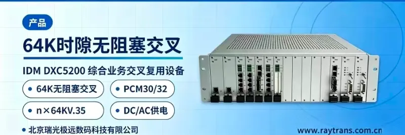
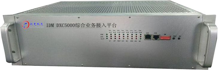
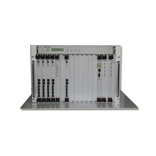
The Wireless PCM integrates PCM technology, PDH technology, Pseudo-Wire Emulation technology, and wireless bridge technology, making it a highly integrated all-in-one access device that allows users to enjoy the high performance of traditional PCM interfaces while rapidly deploying transmission links.
I. Overview
During the construction, operation, and maintenance of airport information and communication systems, situations often arise where new or temporary information points lack fiber optic cabling, where fiber deployment is not feasible, or where existing fiber is damaged. In such cases, a Wireless PDH transmission system is required.
PDH and SDH transmission equipment offer advantages such as constant transmission latency, stable bandwidth, dedicated bandwidth for user terminal services, excellent signal quality, and strong security — advantages that IP-based service terminals cannot replace.
PDH and SDH systems support both fiber optic and wireless transmission modes, providing clock-synchronized or pseudo-synchronized transmission methods. Optical terminals are widely used, while Wireless SDH operates at frequencies above 10 GHz, making the equipment relatively expensive. Wireless PDH, which also uses different uplink and downlink frequencies, is inconvenient to deploy and therefore rarely used. Currently, there is also a Pseudo-Wire Emulation technology that transmits E1 over IP networks, thereby enabling the access of traditional PCM terminals. Pseudo-Wire Emulation allows traditional E1 access technology to be transmitted over wireless bridges, leveraging the vast market advantages of wireless bridge development to ensure that traditional PCM terminals continue to provide high-quality applications with Wireless PDH transmission performance.
The wireless bridge market is enormous, offering high-quality products at competitive prices. Transmission frequencies can be adjusted over a wide range to avoid wireless interference with airport facilities. Since the frequency bands are generally high, and airport line-of-sight conditions are typically favorable, directional antennas can be selected to enhance transmission performance and anti-interference capabilities.
Wireless bridges support point-to-point transmission, point-to-multipoint transmission, and MESH relay transmission modes, offering flexible deployment. Through improved frequency customization technology, they can operate on optimal frequency points, effectively mitigating environmental interference.
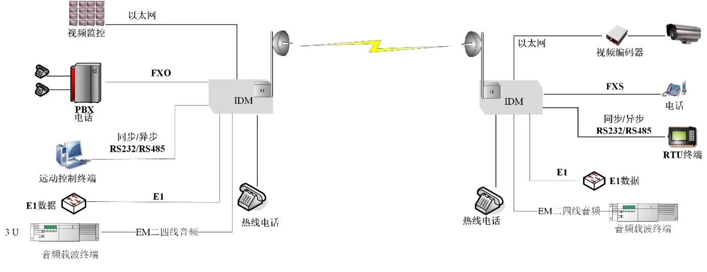
The IDM brand product line provides an integrated Wireless PDH + PCM information access and transmission mode, which can be deployed as conveniently as wireless network products while offering a wide range of PCM service access interfaces, such as FXO/FXS, E&M audio 2-wire/4-wire, synchronous/asynchronous serial data interfaces (RS232/RS422/RS485/RS429/V.35, etc.), and video interfaces.
II. Wireless PCM Device Applications
III. Wireless PCM Technical Principle

IV. Wireless PCM Technical Specifications
The Wireless PCM integrates PCM technology, PDH technology, Pseudo-Wire Emulation technology, and wireless bridge technology, making it a highly integrated all-in-one access device that allows users to enjoy the high performance of traditional PCM interfaces while rapidly deploying transmission links.
4.1 Wireless Transmission Specifications
49206100MHz, RF MIMO adopts a 2T2R architecture, wireless bandwidth supports 5/10/20/40MHz configurable, physical layer bandwidth up to 300Mbps, maximum transmit power 400mW, receive sensitivity up to -96dBm, built-in 18dBi directional dual-polarized antenna, recommended bridge distance 15 kilometers.
Supports TDMA protocol and TDMA bandwidth uplink/downlink allocation function, effectively improving transmission bandwidth in PTMP mode;
Supports Dynamic Frequency Selection (DFS) function;
Supports automatic transmit power adjustment (IEEE802.11h); manual adjustment step 1dBm.
Supports uplink/downlink bandwidth allocation, client isolation, bandwidth control, and client signal strength access control functions;
Supports waterproof rating IP68, operating temperature range -40~75°C;
4.2 E1 Line Specifications
Supports jitter compensation for packet delay variation from 1.5ms to 125ms;
Clock accuracy up to 16ppb, meeting the clock accuracy requirements of 3G base stations, effectively ensuring data backhaul;
Multiple clock modes selectable: internal clock, user clock, recovered clock, and external clock;
Low data transmission latency, minimal signal jitter and wander, ensuring TDM service quality;
Comprehensive indicator light alarm functions for easy fault location by users;
Excellent IP network transmission performance;
Configurable packet buffer space, enabling E1 end-to-end latency as low as 1ms;
Bandwidth adjustment function, allowing E1 interface quantity to be adjusted based on the number of E1 links or the bandwidth conditions of the IP transmission network;
Configurable packet size balanced against PSN throughput and latency, delivering excellent transmission performance over Layer 2 Ethernet switching networks.
E1Interface Bit Rate | 2048Kbpss±50ppm | Number of Ports | 8 |
Standard Protocol | Supports ITU-T G.703 /G.706/G.704 | Line Code | AMI/HDB3 |
Physical Interface | RJ45 (Balanced) / BNC (Unbalanced) | Jitter Performance | ITU-T G.823 |
Impedance | 75Ω(Unbalanced)/120Ω(Balanced) | Clock Recovery Accuracy | 100ppm/16ppb |
E1Interface Configuration | E1 interfaces support local or remote configuration via software | ||
4.3 PCM Interface Specifications
4.3.1 FXO, FXS
Compression Rate | ITU G.711A-Law | Audio Range | 300Hz~3400Hz |
Input/Output Impedance | 200Ω+560Ω//0.1μF | Loop Current | 25mA/Channel |
4.3.2 EM 2/4-Wire
Compression Rate | A-law in ITU G.711 | Audio Range | 300Hz―3400Hz |
Impedance | Balanced600Ω | Return Loss | Not less than18dB |
4.3.3 V.24
Transmission Rate | Asynchronous≤9600bps Synchronous64Kbps | Electrical Characteristics | Compliant withCCITT V.28Protocol |
4.3.4 V.35
Transmission Rate | N×64Kbps (N=1~30) | Electrical Characteristics | Compliant withITU-T V.35 Recommendation |
4.3.5 Co-directional 64K
Line Code | G.703Standard | Line Rate | 64Kbps±100ppm |
Impedance | Balanced120Ω | Fully compliant withITU G.703Recommendation | |
4.4 Video Encoding and Decoding Technical Specifications
Input Interface | HDMI | Supports up to 1920x1080P@60fps Supported resolutions: 1080P, 720P, 1600*1200, 1440*900, 1366*768, 1280*1024, 1024*768, 800*600, 360P, etc. |
Audio | Supports 3.5mm audio signal input and output Supports embedded digital audio from HDMI | |
Audio Encoding | Sampling Rate | 8k, 16k, 32k, 44.1k, 48k |
Bitrate | Configurable, recommended 64k~256k bps | |
Encoding Format | AAC, PCMA, PCMU, MP3, MPEG2 | |
Video Encoding | Bitrate Control | CBR, VBR, AVBR, FIXQP |
Bitrate Range | 16kbps~40Mbps | |
Encoding Format | H264, H265 | |
Network Protocols | Transport Protocols | HTTP, HLS, RTSP, RTMP push, RTMP pull, UDP, unicast, multicast(Multicast) |
Stream Forwarding | Supports secondary forwarding after decoding remote streams |
FAQs
What is the working principle of Pulse Code Modulation (PCM)?
Working Principle Pulse Code Modulation is the process of converting a time-continuous…
View answerPCM30 Working Principle: What Is PCM30/32
PCM30 Equipment Working Principle The 30-channel PCM equipment refers to equipment that provides 30 user interfaces and…
View answerWhat are the common problems of PCM equipment in enterprise applications?
At present, PCM equipment has become basically ubiquitous in enterprise network applications.
View answerWhat is E1? How to Use E1
What is E1 The European 30-channel pulse code modulation PCM is abbreviated as E1, with a rate of 2.048Mbit/s.
View answerFrame Structure of 30/32-Channel PCM Primary Group
A communication system consists of transmitting equipment, receiving equipment, and transmission equipment.
View answer