MESH Wireless PCM
E1 over wireless without optical cable, 8 E1 PCM video integrated, fiber break site commissioned within days
Wireless PCM integrates PCM technology, PDH technology, pseudowire emulation technology, and wireless bridge technology. It is a highly integrated access device that allows users to quickly commission transmission while enjoying the high performance of traditional PCM interfaces.
The MESH Wireless PCM Information Transmission Access Device is an integrated access device developed by Beijing Ruiguang Jiyuan Digital Technology Co., Ltd. It integrates PCM, PDH, pseudowire emulation, and wireless bridge technologies into one unit, and is used for voice, data, and video access at sites without optical fiber, at temporarily added sites, or at sites where the optical fiber is interrupted. It is a PCM equipment for emergency and private network scenarios. A single unit integrates 8 E1 channels, and the service side provides FXO/FXS, EM 2-wire/4-wire, V.24/V.35, codirectional 64K, and HDMI video interfaces, meeting the product showcase requirements for carrying multiple services such as voice, data, and video.
For substations, railway sections, and field mobile sites, commissioning a PCM service previously required waiting for optical cable laying or installing multiple protocol conversion devices. MESH Wireless PCM carries E1 over a wireless link, so a site can be commissioned as long as line-of-sight and power supply conditions are met, while the interface form on the service terminal side remains unchanged. As an integrated service access device, it is also suitable for supplementary and extension scenarios of the Raytrans military emergency communications vehicle solution and the government private network optical fiber communication solution.
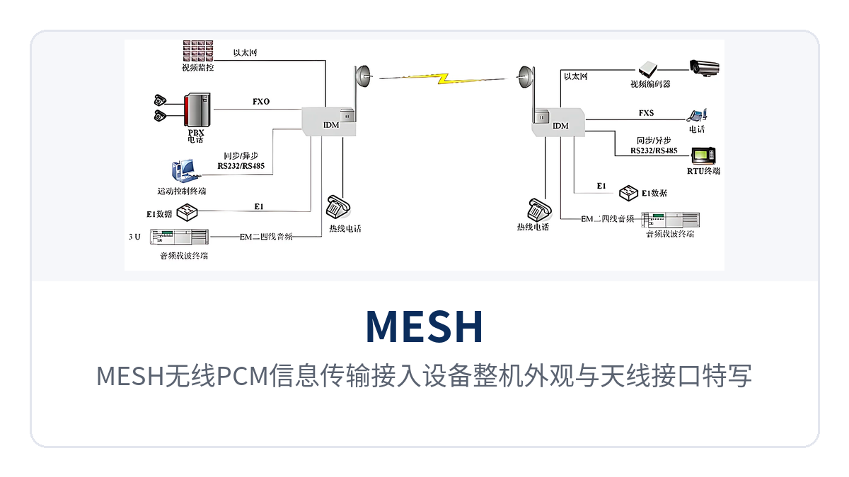
Figure 1: Overall appearance of the MESH Wireless PCM Information Transmission Access Device and close-up of the antenna interfaces
Key Specifications at a Glance: 8 E1 access · 2048Kbps±50ppm · ITU-T G.823 jitter · 16ppb clock recovery · 1080P@60fps · IP68 outdoor protection · 1~5 km bridging
What Is the MESH Wireless PCM Device? How Does a Wireless Link Carry Traditional PCM Services
MESH Wireless PCM is a PCM equipment that combines wireless transmission and PCM service access. In essence, it carries the E1 bit stream over an IP wireless link, so that traditional PCM terminals keep their original interfaces and dial-up mode unchanged. One end of the device connects to telephone, audio, serial data, and video services, while the other end sends the encapsulated stream to the opposite site over a wireless bridge, where it is restored to an E1 signal and connected to the existing transmission system.
Pseudowire emulation (TDM over IP) is the core of this product showcase access mode. This technology encapsulates the 2048Kbps E1 bit stream into IP packets frame by frame, transmits them over the wireless link to the opposite end, and then reshapes them into a standard E1 signal, while the service interfaces and signaling modes at both ends remain unchanged.
Compared with laying optical cables along the line, this access mode eliminates pole routes, ducts, and splicing. As long as line-of-sight conditions between sites are met, the device can be commissioned once powered on and configured with the operating frequency and bandwidth, shortening the project cycle from weeks to days. For temporary sites used only during the construction period, the PCM equipment can be relocated as the project progresses, with no need to build a dedicated line for short-term services.
What Are the Core Functions
The functions are organized around four threads: E1 carrying, PCM service access, wireless bridging, and video codec. The table below lists each function item and its purpose for comparison against the on-site service list. Each item in the table can be confirmed on site through indicator LEDs and service testing, and during selection you can simply compare them one by one against the service list.
| Function | Description |
|---|---|
| E1 service access | A single unit integrates 8 E1 interfaces with a bit rate of 2048Kbps±50ppm, and each channel can independently carry PCM services |
| PCM voice access | Provides FXO/FXS interfaces with G.711 A-law compression and an audio range of 300Hz~3400Hz, used for telephone and fax |
| EM 2-wire/4-wire audio | Balanced 600 Ω, return loss no less than 18 dB, used for dispatch console, PA, and audio dedicated line |
| Serial data access | V.24 supports asynchronous ≤9600bps and synchronous 64Kbps; V.35 supports N×64Kbps (N=1~30) |
| Codirectional 64K interface | G.703 standard 64Kbps±100ppm, balanced 120 Ω, used for protection channel and telecontrol data |
| Pseudowire emulation | Encapsulates the E1 bit stream into IP packets for transmission over the wireless link and restores E1 at the opposite end, with service interfaces unchanged |
| Wireless bridging | Supports point-to-point, point-to-multipoint, and MESH relay networking, with a bridging distance of 1~5 km |
| E1 software configuration | E1 interfaces support software-based local or remote configuration, so unattended sites can be reconfigured without a site visit |
| Video codec | HDMI input supports 1920x1080P@60fps, H.264/H.265 encoding, and a bit rate range of 16kbps~40Mbps |
| Audio codec | 3.5mm analog audio and HDMI embedded digital audio, sampling rate 8k~48k, supporting AAC, PCMA, PCMU, MP3, and MPEG2 |
| Stream forwarding | Supports secondary forwarding after decoding the remote stream, so video can be relayed between multi-level sites |
| Outdoor protection | IP68 waterproof rating, operating temperature -40~75℃, supporting pole-mounted installation |
Key Specifications: E1 Interface, PCM Service Interface, and Wireless Link Indicators
E1 interface parameters determine whether services can run stably, while PCM interface parameters determine whether on-site terminals can be connected directly. The table below lists E1 specifications item by item, and the parameters are subject to the product documentation. When checking, first verify whether the bit rate, line coding, and impedance match those of the opposite end device, and then check whether the jitter and clock specifications meet long-link requirements.
| Item | Parameter/Specification | Description/Applicable Conditions |
|---|---|---|
| E1 interface bit rate | 2048Kbps±50ppm | Complies with ITU-T G.703 |
| Number of channels | 8 | A single unit integrates 8 E1 access channels, eliminating equipment stacking |
| Standard protocol | ITU-T G.703/G.706/G.704 | Frame structure and signaling are organized per G.704 |
| Line coding | AMI/HDB3 | Configure consistently with the line coding of the opposite end device |
| Physical interface | RJ45 connector (balanced)/BNC (unbalanced) | Optional per on-site cables and equipment room practice |
| Impedance | 75 Ω (unbalanced)/120 Ω (balanced) | Selected to match the interface form |
| Jitter characteristics | ITU-T G.823 | Carries telephone and telecontrol channels at remote sites on long links |
| Clock recovery accuracy | 100ppm/16ppb | Meets the clock accuracy requirements of base stations and protection channels |
| Jitter compensation | 1.5ms~125ms packet delay deviation | Handles latency variation of the wireless link |
| E1 interface configurable | Supports software-based local or remote configuration | Remote sites can be reconfigured and commissioned without a site visit |
PCM service interfaces cover four categories: voice, audio, serial data, and codirectional 64K. The table below lists the key specifications and common services of each interface type. Interfaces are configured as required, different services can be accessed in a mixed manner on the same integrated service access device, and during capacity expansion you only need to add interfaces according to the remaining E1 time slots.
| Interface Type | Key Specifications | Applicable Services |
|---|---|---|
| FXO/FXS | G.711 A-law, audio 300Hz~3400Hz, input/output impedance 200Ω+560Ω//0.1μF, loop current 25mA per channel | Telephone, fax, loop-start trunk |
| EM 2-wire/4-wire | G.711 A-law, audio 300Hz~3400Hz, balanced 600 Ω impedance, return loss no less than 18 dB | Dispatch console, PA, audio dedicated line |
| V.24 | Asynchronous ≤9600bps, synchronous 64Kbps, compliant with CCITT V.28 | RTU, protection device, monitoring data |
| V.35 | N×64Kbps (N=1~30), compliant with ITU-T V.35 | Router interconnection, video consultation |
| Codirectional 64K | G.703 standard, 64Kbps±100ppm, balanced 120 Ω impedance | Protection channel, telecontrol data |
The wireless link and video codec specifications determine the link commissioning conditions and video carrying capacity, as listed in the table below. Before commissioning, first confirm that the operating frequency and transmit power comply with local wireless regulations, then determine the channel bandwidth according to service volume and link margin, and set the video bit rate with a margin reserved for the on-site bandwidth.
| Item | Parameter/Specification | Description/Applicable Conditions |
|---|---|---|
| Operating frequency band | 4920~6100MHz | Configured per local frequency regulations |
| RF architecture | 2T2R MIMO | Dual transmit and dual receive improve link throughput |
| Channel bandwidth | 5/10/20/40MHz configurable | Selected according to service volume and interference |
| Physical layer bandwidth | 300Mbps | Used for PCM services and video sharing the link |
| Transmit power | 400mW, adjustable in 1dBm steps | Adjusted per link according to station spacing, balancing connectivity and interference |
| Receiver sensitivity | -96dBm | Maintains the link under weak signal conditions |
| Antenna | Built-in 18dBi directional dual-polarized antenna | A directional antenna can be used to enhance the link when line-of-sight conditions are good |
| Bridging distance | 1~5 km | MESH relay can be used beyond this range |
| Wireless protocol | TDMA, DFS, IEEE 802.11h | Supports uplink/downlink bandwidth allocation for point-to-multipoint |
| Protection and temperature | IP68, -40~75℃ | Pole-mounted outdoor installation, suitable for field environments |
| Video input | HDMI, supporting 1920x1080P@60fps | Compatible with resolutions such as 1080P, 720P, 16001200, 1440900, 1366768, 12801024, 1024768, 800600, and 360P |
| Video encoding | H.264/H.265, CBR, VBR, AVBR, FIXQP | Bit rate range 16kbps~40Mbps |
| Audio interface | 3.5mm audio input/output, HDMI embedded digital audio | Sampling rate 8k, 16k, 32k, 44.1k, 48k |
| Transmission protocol | HTTP, HLS, RTSP, RTMP push and pull streaming, UDP, unicast and multicast | Can connect to existing video platforms |
At the solution implementation level, Raytrans can provide a wireless PCM access combination for the military emergency communications vehicle solution, and can also provide matching selection of PCM equipment and integrated service access devices for the government private network optical fiber communication solution, making it easy to configure flexibly according to the service list in different scenarios.
Differentiated Value: What Three Specifications Mean on a Private Network Site
The three specifications are not paper parameters; they directly correspond to the number of devices at a site, long-link stability, and the number of O&M site visits. The table below maps each selling point to its on-site impact one by one, and when selecting a wireless PCM access device you can directly cite the quantitative conditions and applicable premises therein.
| Differentiation Point | What It Means on a Private Network Site |
|---|---|
| 8 E1 channels integrated in a single unit | One site uses one PCM equipment to access 8 E1 channels and various PCM services, so multiple PCM equipment and protocol converters are no longer stacked in the cabinet, reducing both the product showcase footprint and equipment investment |
| G.823 jitter and 16ppb clock accuracy | E1 jitter complies with ITU-T G.823 and the clock recovery accuracy is 16ppb, giving a solid basis for telephone and telecontrol channels at remote sites on long links |
| Remote software configuration | E1 interfaces support software-based local or remote configuration, and the remote software E1 configuration capability means unattended sites in the field no longer require a site visit for reconfiguration |
| 1080P@60fps | HDMI video supports 1920x1080P@60fps, and site video and PCM services share one wireless link, with no need to build a separate video channel |
Typical Application Scenarios
Electric Power and Energy Private Networks: Substations, Hydropower Stations, and Oil and Gas Pipeline Routes
Optical cables usually already exist between substations and switching stations, but new bays, temporary construction power points, river crossings, and old hydropower stations often have no available optical fiber during capacity expansion. MESH Wireless PCM provides transitional and supplementary access at these sites, with one PCM equipment accessing 8 E1 channels while carrying dispatch telephone, telecontrol data, and protection channels.
Valve chambers and cathodic protection stations along oil and gas pipelines are far apart and have no fixed equipment room. The devices are connected in series for backhaul in point-to-point or MESH relay mode, and the IP68 protection and -40~75℃ operating temperature suit field environments. E1 jitter complies with ITU-T G.823 and the clock recovery accuracy is 16ppb, so services remain stable after multi-level relaying on long links.
Rail Transit and Expressway Electromechanical Systems: Communication Access Along the Line
Rail transit section equipment points, expressway toll stations and tunnel management offices are scattered on both sides of the line, where trackside and roadside cabling involves long approval cycles and poor excavation conditions. MESH wireless PCM is deployed point by point, using wireless links to carry section telephones, public address (PA) audio and monitoring data back to stations or management centers.
Line-of-sight conditions at tunnel portals and elevated sections determine link quality. The equipment supports point-to-multipoint aggregation, so a single master station at the central station can provide coverage in multiple directions. Video and PCM services are carried on separate bandwidth allocations; for capacity expansion, it is enough to adjust the channel bandwidth among 5/10/20/40 MHz.
Border and Coastal Defense and Emergency Private Networks: Field Mobility and Unattended Sites
Border and coastal defense outposts and field mobile scenarios require the equipment to be on air as soon as it is in place, with no waiting for civil works or optical cable installation. MESH wireless PCM can be installed at outposts, command vehicles and hilltop relay points to extend the link hop by hop through MESH relay and to send telephones, serial data and on-site video from the front end back to the command post; in military emergency communications vehicle solutions, such integrated service access devices also allow quick deployment in a vehicle-mounted mobile configuration.
For unattended sites in the field, O&M difficulties concentrate on reconfiguration: changing a single parameter means sending someone to the site. The equipment supports local or remote software configuration of the E1 interfaces, so O&M personnel can adjust E1 parameters and service allocation from the central side. After a power failure and restart, the equipment resumes operation with the saved configuration, cutting the time and vehicle costs of travelling to the site.
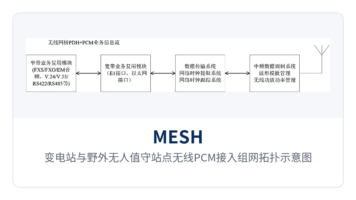
Figure 2: Networking Topology Diagram of Wireless PCM Access at Substations and Unattended Field Sites
How to Deploy and Commission: Five Steps on Site
On-site commissioning proceeds in five steps, each with check items that can be verified, so that repeated rework after commissioning is avoided. The sequence below follows the principle of wireless first, services second: do not move on to the next step until the key metrics of the previous one are confirmed, which markedly reduces back-and-forth in joint testing and second site visits.
- Survey link conditions: confirm line-of-sight between the sites at both ends, the antenna mounting height and any obstructions, and decide by hop distance whether a MESH relay is needed; at the same time, check whether the same frequency band is already occupied by existing wireless systems.
- Configure the wireless link: set the operating frequency, the channel bandwidth (5/10/20/40 MHz) and the transmit power (in 1 dBm steps), and enable TDMA uplink and downlink bandwidth allocation for point-to-multipoint networking.
- Configure the E1 and PCM interfaces: set the E1 line coding (AMI or HDB3) and the impedance (75 Ω or 120 Ω) to match the equipment at the opposite end, and allocate voice channels, audio, data and 64 kbit/s service time slots channel by channel.
- Commission services and jitter: dial-test telephones and fax machines one by one, verify transmit and receive on the data channel, and observe whether the E1 alarm indications and jitter figures fall within the ITU-T G.823 range.
- Record and back up the configuration: the frequency, bandwidth, E1 parameters and service allocation table are saved and incorporated into the site records; for remote stations, open a remote configuration channel so that later reconfiguration needs no site visit.
Conclusion
The MESH Wireless PCM Information Transmission Access Equipment integrates eight E1 channels, PCM service interfaces, pseudowire emulation and a wireless bridge into the unit, replacing optical cable laying with wireless links and providing an access approach that supports rapid commissioning for a site without optical fiber in electric power, rail transit and emergency private networks. When selection and networking design are needed for a specific site, configuration recommendations and a commercial quotation can be provided based on hop distance, service list and interface type.