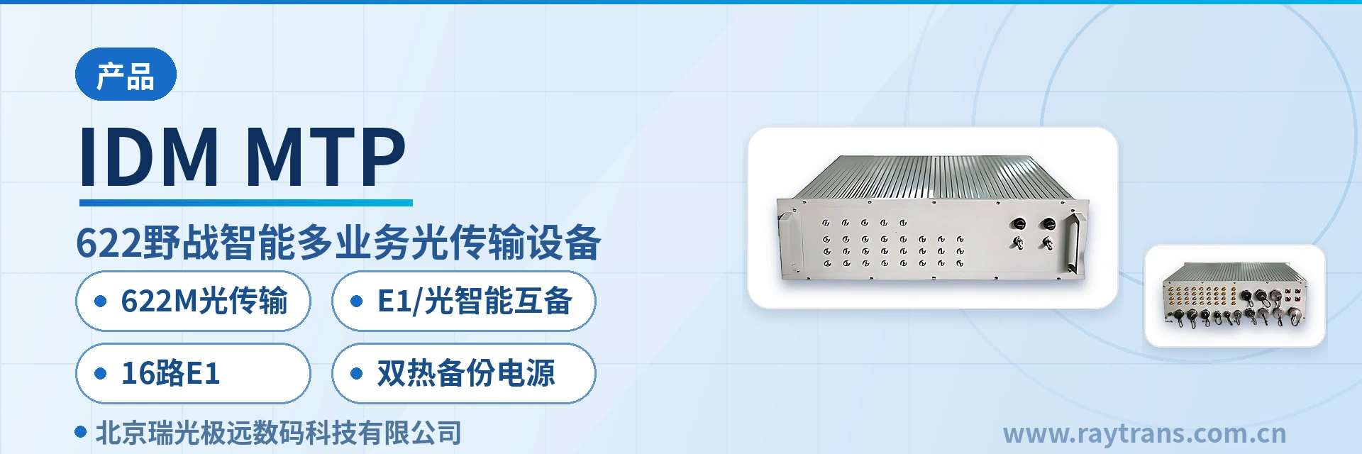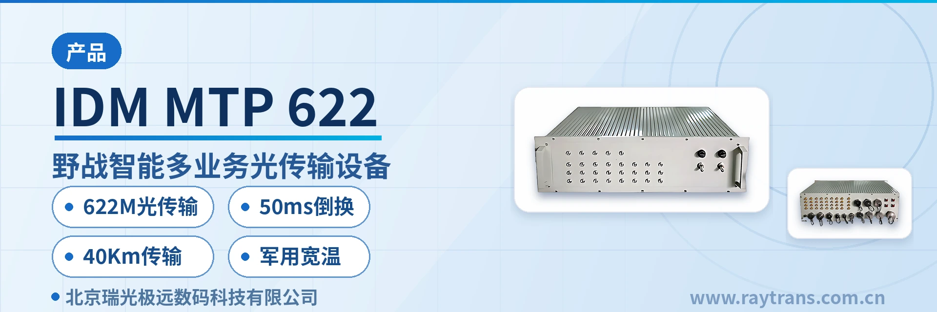
IDM MTP-622 Field Intelligent Multi-Service Optical Transmission Equipment
STM-4, automatic switchover on fiber break, E1 link, guaranteed call continuity within 50 ms
The IDM MTP-622 Field Intelligent Multi-Service Optical Transmission Equipment is designed specifically for military field communications. It adopts a modular functional design and consists of an SDH optical transmission unit, an E1 link interface control unit, an EOS unit, a PCM unit, an SNMP unit, and a protection switching unit. With a shockproof, waterproof, and EMC-compliant chassis design, it multiplexes E1 signals, audio signals, telephone/magneto signals, and wire-speed 100M Ethernet signals for transmission over STM-4 (622 Mbit/s) optical fibers and E1 channels, and supports intelligent mutual backup between STM-4 optical fiber and E1 link transmission channels.
IDM MTP-622 Field Intelligent Multi-Service Optical Transmission Equipment (622M field optical multiplexer) is a field optical transmission equipment developed by Beijing Ruiguang Jiyuan Digital Technology Co., Ltd. It multiplexes E1 signals, audio signals, telephone/magneto signals, and wire-speed 100M Ethernet signals into STM-4 (622 Mbit/s) optical fiber channels and E1 link channels for unified transmission, and supports intelligent mutual backup of transmission channels between STM-4 optical fiber links and E1 links. IDM MTP-622 belongs to the 622M (STM-4) model of the Field Intelligent Multi-Service Optical Transmission Equipment series. It is designed for scenarios such as military emergency communications, field training bases, and field communication vehicles. The unit is designed for rapid setup and mobile relocation in field operations, and can be deployed as central office or remote-end equipment, making it a reliable choice for emergency communications and government private network optical fiber communication solutions.
The 622M field optical multiplexer connects telephone, magneto, E1, V.35/V.24 data, and Ethernet services to the same field transmission network: when the optical fiber channel is normal, all services are transmitted over the 622 Mbit/s optical fiber; when the optical cable is interrupted, services are automatically switched to the E1 link for fallback transmission, and automatically switched back after the optical fiber is restored, meeting the requirement of uninterrupted voice and critical data services under field conditions. Compared with ordinary transmission equipment with a single optical fiber channel, IDM MTP-622 uses STM-4 optical fiber and E1 link dual-channel mutual backup as the fiber break fallback means. It is suitable for unattended operation with field communication vehicles during mobile operations and rapid link establishment, and can also serve as a reference for optical transmission equipment selection in military emergency communications vehicle solutions.
Key Specifications at a Glance: Optical port rate 622 Mbit/s (2 hot-swappable SFP) · E1 circuit interface 16 channels · Fast Ethernet 4 channels · 2-wire/4-wire voice 20 channels · Optical/E1 switchover ≤50 ms · Single-mode transmission distance 40 km · AC/DC power supply dual hot standby · 19-inch 3U chassis
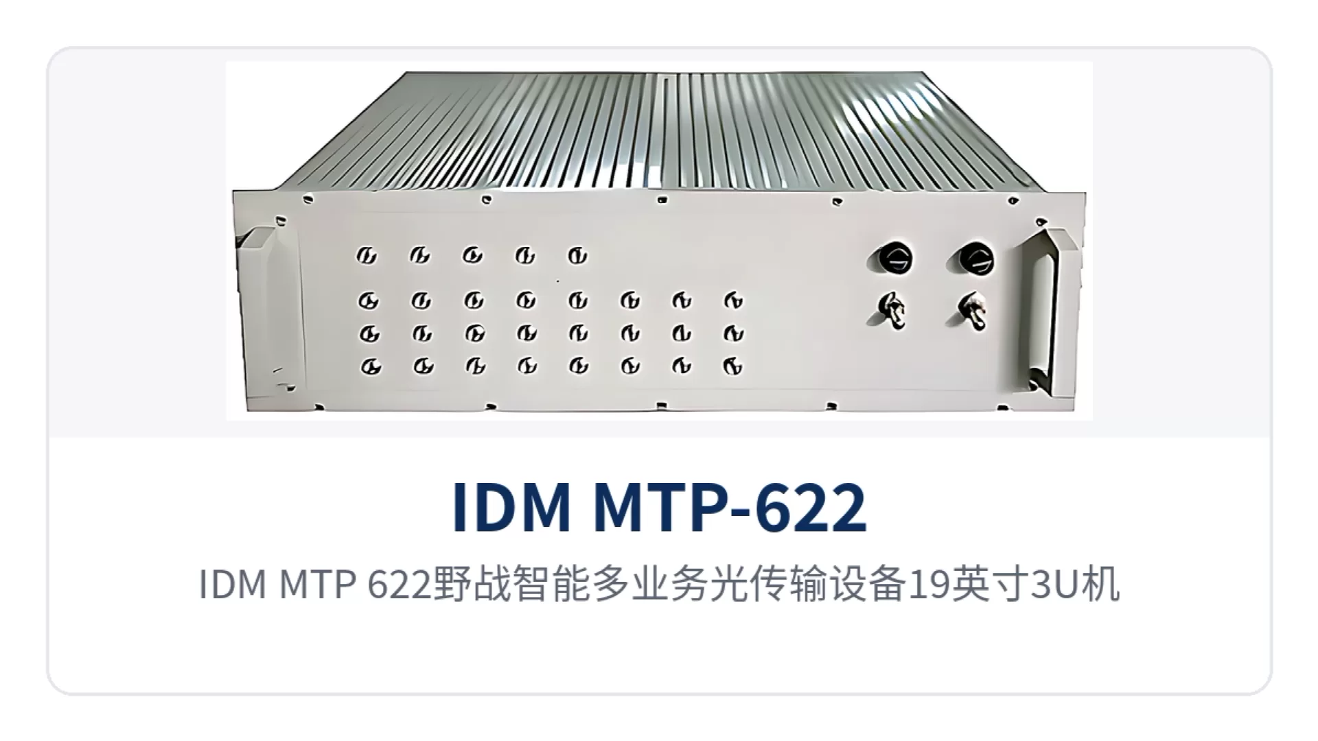
Figure 1: IDM MTP-622 Field Intelligent Multi-Service Optical Transmission Equipment 19-inch 3U chassis front view and circular/aviation connector service interface layout
What Is a 622M Field Optical Multiplexer? What Are the Components of the Unit?
The 622M field optical multiplexer is a field communications transmission equipment designed at a rate of 622 Mbit/s. IDM MTP-622 is its STM-4 rate model. The optical interface rate and line specifications comply with ITU-T G.957, and the E1 link interface complies with ITU-T G.703. The unit adopts a modular functional design and consists of an SDH optical transmission unit, an E1 link interface control unit, an EOS unit, a PCM unit, an SNMP unit, and a protection switching unit. It uses a 19-inch 3U standard chassis structure with shockproof, waterproof, and EMC chassis design. The service access slots are universal and can accept required service boards according to user configuration requirements. As a professional SDH equipment manufacturer, Raytrans has integrated mature SDH equipment and optical transmission equipment technologies into this model, providing a reliable transmission platform for scenarios such as emergency communications and military emergency communications vehicle solutions.
In terms of standard configuration, IDM MTP-622 provides 4 channels of 10/100M Ethernet, 16 channels of E1 circuits, 16 channels of 2-wire and 4 channels of 4-wire voice, 1 channel of V.35, 2 channels of V.24 interfaces, and 1 channel of E1 link interface. In addition to the standard configuration, there are 4 expansion slots for various service boards. All service interfaces use circular/aviation connector types, ensuring reliable plugging and unplugging and freedom from loosening. Together with the shockproof chassis, this makes the equipment suitable for rapid setup and frequent relocation in field operations. The optical port uses hot-swappable SFP modules, supporting optical port replacement for on-site emergency repair and spare parts replacement.
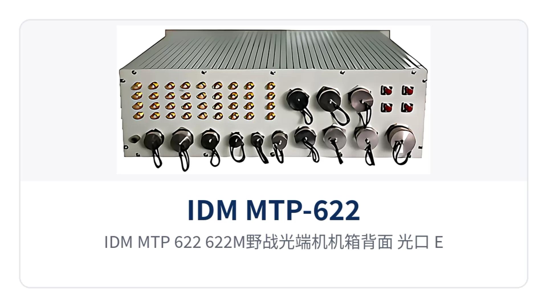
Figure 2: IDM MTP-622 622M field optical multiplexer chassis rear view: optical port, E1, voice, and data interface board layout
IDM MTP-622 Field Optical Multiplexer Core Functions
The functions of IDM MTP-622 field optical multiplexer are designed around dual-link mutual backup, multi-service access, telephone switching, network management and monitoring, and military-standard environmental adaptability. The main function items are listed in the table below.
Function | Description |
|---|---|
Dual-link intelligent mutual backup | Supports intelligent mutual backup between STM-4 optical fiber links and E1 links. When an optical cable failure occurs, 2M services are automatically switched to the E1 link for transmission, and automatically switched back after the optical fiber is restored |
Unified multi-service access | Standard configuration provides 4 channels of 10/100M Ethernet, 16 channels of E1 circuits, 16 channels of 2-wire + 4 channels of 4-wire voice, 1 channel of V.35, 2 channels of V.24 interfaces, and 1 channel of E1 link interface, plus 4 expansion slots |
5-in-1 2-wire audio card | Each audio card provides 16 channels of 2-wire audio, and each 2-wire audio channel can be configured as FXO/FXS/hotline/magneto/2100 Hz magneto mode |
Local telephone switching | Supports local telephone switching, provides 1~2 channels of E1 digital trunk interfaces, supports SS7, PRI, and No.1 signaling, and can access the telephone switching network via digital trunks |
SNMP network management and northbound interface | Supports SNMP network management protocol for service configuration of remote-end devices; provides a northbound interface (NBI) for uploading alarm information, and is capable of accessing the military-wide optical fiber communication transmission network management system |
Power supply and optical port redundancy | Supports dual hot standby power supplies; the optical port uses hot-swappable SFP modules, supporting optical port replacement |
Military-standard environmental adaptability | EMC design complies with relevant provisions of GJB151A-1997 for ground equipment of the army; electromagnetic emission and susceptibility tests comply with GJB152A-1997; meets the vibration, shock, and drop requirements of GJB367A-2001, with waterproof and moisture-proof design |
Circular/aviation connector interface | All service interfaces use circular/aviation connector types, ensuring reliable plugging and unplugging, suitable for rapid setup and mobile use in field operations |
The 5-in-1 2-wire audio card is the core board for voice access in IDM MTP-622. Each card provides 16 channels of 2-wire audio, and each channel can be independently configured as FXO, FXS, hotline, magneto, or 2100 Hz magneto mode. A single card can accommodate various access objects such as user telephones, trunk lines, hotlines, and magneto telephones. The order wire interface is used for field service communication. One pair of synchronous clock interfaces can introduce an external input clock and output a synchronous clock to the equipment, facilitating clock synchronization with the upper-level transmission network. This model can serve as a core transmission node for field optical transmission equipment and field communication vehicles, undertaking multi-service aggregation and transmission tasks in emergency communications and government private network optical fiber communication solutions.
What Interfaces Are in the Standard Configuration of a Field Optical Multiplexer? Technical Specifications Overview
What interfaces are in the standard configuration of a field optical multiplexer is the first question to verify when selecting equipment for field communications networking. The standard configuration of IDM MTP-622 covers four types of services: Ethernet, E1, voice, and low-speed data. The specific specifications of line and service interfaces are listed in the table below.
Item | Parameter/Specification | Description/Applicable Conditions |
|---|---|---|
Optical fiber line interface | Quantity: 2; rate: 622 Mbit/s; compliant with ITU-T G.957 | SFP optical port, hot-swappable; single-mode (multi-mode optional); wavelength 1310 nm or 1550 nm |
Optical interface technical specifications | Transmit optical power -15~-8 dBm; receiver sensitivity better than -32 dBm | Standard single-mode configuration: transmission distance 40 km; long-distance optical modules optional for longer transmission distance |
E1 link interface | Quantity: 1; rate: 2.048 Mbps; compliant with ITU-T G.703 | Used as a mutual backup transmission channel for the optical fiber link |
E1 circuit interface | Quantity: 16; unbalanced; rate: 2.048 Mbps; compliant with ITU-T G.703 | Used for access of 2M services |
E1 interface technical specifications | Line coding: HDB3; bit rate: 2048 Kbps±50 ppm; impedance: 70 Ω (unbalanced); frame structure: PCM31/30; channel-associated signaling | Jitter compliant with ITU-T G.823; supports ITU-T G.703/G.704; framing/non-framing configurable, time slots configurable |
Ethernet interface | Quantity: 4; rate: 10M/100M adaptive; RJ45 connector; compliant with IEEE802.3 | Half/full-duplex; wire-speed 100M Ethernet signal transmission |
V.35 interface | Quantity: 1; rate: N×64 Kbit/s (N≤30); compliant with ITU-T V.35 | Supports DCE and DTE modes; specification N×64K (N≤32) |
RS232 interface | Quantity: 2; rate: ≤19.2 Kbit/s; compliant with EIA RS232 | Supports RS232/RS485: asynchronous rate ≤19.2K adaptive, synchronous rate 64K |
2-wire/4-wire voice interface | Quantity: 20 channels (4 channels of 4-wire, 16 channels of 2-wire); rate: 64 Kbit/s | Modes: hotline, magneto, subscriber, trunk |
Order wire interface | Quantity: 1 | Used for field service communication |
Synchronous clock interface | 1 pair: 1 external input clock interface, 1 output synchronous clock interface | Used for clock synchronization with the upper-level transmission network |
Management interface | Interface characteristics compliant with relevant IEEE802.3 provisions; communication protocol: SNMP | The network management system provides a northbound interface (NBI) and is capable of accessing the military-wide optical fiber communication transmission network management system |
The electrical specifications of voice interfaces vary by interface type. The 2-wire/4-wire voice interface can operate in hotline, magneto, subscriber and trunk modes. The main electrical parameters of each type are listed in the following table.
Interface type | Main electrical specifications |
|---|---|
FXS interface | Frequency band 300~3400 Hz; impedance (200 Ω+560 Ω//104); loop resistance <2 KΩ; receive level -3.5 dBr, transmit level 0 dBr, idle voice channel noise <-65 dBmop, crosstalk ≤-65 dBmop |
FXO interface | Frequency band 300~3400 Hz; impedance (200 Ω+680 Ω//104); transmit level 0 dBr, receive level -3.5 dBr, crosstalk ≤-65 dBmop, idle voice channel noise <-65 dBmop |
Magneto telephone/2100 Hz carrier magneto interface | Frequency band 300~3400 Hz; impedance 600 Ω; transmit level 0 dBr, receive level -3.5 dBr, crosstalk ≤-65 dBmop, idle voice channel noise <-65 dBmop |
Hotline telephone interface | Frequency band 300~3400 Hz; impedance 600 Ω; loop resistance <2 KΩ; receive level -3.5 dBr, transmit level 0 dBr, idle voice channel noise <-65 dBmop, crosstalk ≤-65 dBmop |
As a professional manufacturer among optical multiplexer manufacturers, Raytrans has long been deeply engaged in the fields of SDH equipment and optical transmission equipment. Its MSTP and SDH equipment manufacturer capabilities can provide complete support from product showcase to system integration for military emergency communications vehicle solutions, government private network optical fiber communication solutions and various emergency communications projects.
How Is Field Communications Restored After a Fiber Interruption? The Principle of Intelligent Mutual Backup of E1 Links
How field communications are restored after a fiber interruption depends on the link establishment mode of the E1 link mutual backup channel and the switchover mechanism of the equipment. The normal transmission state of the IDM MTP-622 is as follows: all services are transmitted over the 622 Mbit/s optical fiber channel, Ethernet services are configured with 2M bandwidth granularity, providing N×2M high-bandwidth Ethernet transmission; when the optical fiber channel fails, the protection switching unit automatically switches services to the E1 link channel, transmitting services on the E1 channel at specified 64K and N×64K, while Ethernet services are reconfigured with 64K bandwidth granularity, providing N×64K low-bandwidth Ethernet transmission, ensuring that voice and critical data services are not interrupted; after the optical fiber channel recovers, the equipment automatically switches all services back to optical fiber transmission. The whole process requires no manual intervention and is suitable for unattended operation in mobile scenarios such as field communication vehicles, providing reliable assurance for emergency communications.
Knowledge block: The time for 2M services on the optical cable link to switch over to the E1 link corresponds to the link establishment mode of the E1 link. The switchover time data is shown in the following table; in hot standby mode, the switchover is completed automatically inside the equipment, which is applicable to scenarios where the E1 link has been pre-established and maintained.
Link establishment mode | Time for 2M service switchover to the E1 link | Applicable conditions |
|---|---|---|
Hot standby mode | ≤50ms | The E1 link is pre-established and maintained, and switchover is completed automatically |
Dial-up mode | ≤15s | The E1 link needs to be established temporarily by dial-up |
Integrated network management mode | ≤50s | The E1 link is established through integrated network management |
In terms of bit error characteristics, the IDM MTP-622 optical fiber link complies with the relevant provisions of ITU-T G.826, which can be used to evaluate the transmission quality of the optical fiber channel. The switchover status and link alarms can be viewed remotely through SNMP network management, based on which field communications support personnel can grasp the link status and determine whether personnel need to be dispatched for handling; after the optical cable is repaired, the device automatically switches all services back to optical fiber transmission, with no communication interruption during the process.
How Is a Field Communication Vehicle Optical Multiplexer Deployed? Typical Application Networking
How a field communication vehicle optical multiplexer is deployed is generally organized by pairing a central office with a remote end and providing both optical fiber and E1 transmission channels at the same time. In the application solution, the central office and the remote end are each equipped with one IDM intelligent multi-service optical transmission device, and the transmission line adopts 622M (STM-4) optical fiber and E1 link mutual backup transmission channels; the central office device can access the telephone switching network through FXO analog trunk or E1 digital trunk, access the IP network through a Fast Ethernet interface, and simultaneously provide access for V.35, V.24, hotline phone, ordinary telephone, E1 and 4-wire audio services; the remote end device can be deployed at a field training base or installed on a field communication vehicle, providing access for services of the same class, offering ready-to-use transmission channels for training, exercises and mobile missions, and meeting the networking requirements of the military emergency communications vehicle solution.
Field Communication Vehicle Deployment Points
The requirements of a field communication vehicle for transmission equipment are shock resistance, reliable interfaces and ready-to-use on arrival. The IDM MTP-622 enclosure meets the requirements for vibration, shock and drop in GJB367A-2001 General Specification for Military Communications Equipment, all service interfaces adopt the circular/aviation connector type, power supply supports DC -48V/DC 24V vehicle-mounted direct current and AC 220V alternating current, the operating temperature is -25℃~55℃ and the relative humidity is ≤95% non-condensing; the vehicle-mounted equipment connects to the central office of the command post through dual channels of a 622M optical fiber and an E1 link. When the optical fiber is normal, services run over the optical fiber, and when the optical fiber is damaged or broken, services are automatically switched over to the E1 link for fallback transmission. After the field communication vehicle arrives at the designated position, the transmission link with the command post can be enabled by connecting the power supply and the optical cable, maintaining contact as a mobile repeater node.
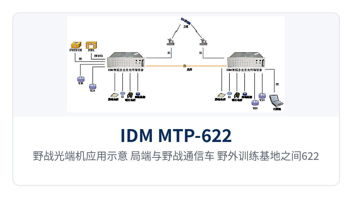
Figure 3: Field optical multiplexer application diagram: mutual backup networking of a 622M optical fiber and an E1 link between the central office and a field communication vehicle or field training base
Networking Between a Field Training Base and a Command Post
The distance between a field training base and a command post usually exceeds the direct connection range of electrical interfaces such as telephone lines, and mutual backup of optical fiber and E1 dual channels is a commonly used transmission organization method. After one field optical multiplexer is installed at each of the central office and the remote end, the transmission line adopts 622M (STM-4) optical fiber and E1 link mutual backup transmission channels, and telephone, magneto, data, Ethernet and 2M services can all be accessed; when the optical fiber channel is in good transmission status, all services are transmitted over the 622M optical fiber, and when the optical fiber fails, services are automatically switched over to the E1 link, and after the optical fiber is repaired, services are automatically switched back, ensuring continuous communication links during training and exercises. The IDM MTP-622 can also serve as mobile repeater equipment to access the existing 2M bearer network, extending the mutual backup range to the higher-level optical fiber communication transmission network.
Emergency Communications and Industrial Private Network Scenarios
The emergency communications link at a disaster relief and rescue site needs to be rapidly commissioned without equipment room conditions and to withstand uncertainties brought by vehicles, power supply and weather. The IDM MTP-622 has an operating temperature of -25℃~55℃ and a relative humidity of ≤95% non-condensing, its power supply supports AC 220V (187V253V) and DC -48V (-38V-58V)/DC 24V (-19V~-28V), and it can be connected to vehicle-mounted direct current or on-site alternating current power; all service interfaces adopt the circular/aviation connector type; after being set up at the rescue site, telephone, E1 and Ethernet services can be sent back to the rear command node, and when the optical cable is damaged during road clearance and power restoration, services are automatically switched over to the E1 link for fallback transmission.
In industrial private networks such as electric power and rail transit, sites are distributed along the line with large spacing between stations, and 2M (E1) channels and Fast Ethernet are commonly used ways of inter-station bearer. The IDM MTP-622 provides 16 E1 circuit interfaces (complying with ITU-T G.703) and 4 10M/100M adaptive Ethernet interfaces, and can simultaneously carry inter-station 2M services and IP data; with a -25℃~55℃ wide operating temperature range and compliance with the vibration, shock and drop requirements in GJB367A-2001, it is suitable for deployment in cabinets along the line, on vehicles and at temporary sites.
Differentiated Value of the IDM MTP-622: No Service Interruption on Fiber Break, Multi-Service Aggregation in a Standalone Unit
No service interruption on fiber break is a differentiated capability of the IDM MTP-622. The device uses an STM-4 optical fiber as the primary channel and an E1 link as the mutual backup channel. When the optical cable is interrupted by external forces such as excavation during construction and vehicle rolling, the protection switching unit automatically switches 2M services over to the E1 link, and when hot standby mode is adopted, the switchover time is ≤50ms, so voice and critical data services remain continuous during optical cable emergency repair; when the E1 link needs to be established temporarily, the dial-up mode takes ≤15s and the integrated network management mode takes ≤50s, and the switchover process requires no manual intervention, making it suitable for unattended mobile sites such as field communication vehicles.
The 622Mbit/s optical port rate and 40km standard single-mode transmission distance meet long-distance high bandwidth access in the field. The IDM MTP-622 is equipped with 2 622Mbit/s optical fiber line interfaces, with characteristics complying with the ITU-T G.957 standard, a transmit optical power of -15~-8dBm and a receiver sensitivity better than -32dBm, and a standard single-mode configuration transmission distance of 40km; when a longer distance is required, a long-distance optical module can be optionally installed; when the optical fiber channel is in good status, Ethernet services are configured with 2M as the bandwidth granularity, providing N×2M high bandwidth Ethernet transmission, which is sufficient to cover the link requirements between the command post and a field communication vehicle or field training base.
One 19-inch 3U device completes multi-service aggregation, which is the third differentiated capability of the IDM MTP-622. The standard configuration of the unit provides 16 E1 circuit interfaces, 4 10/100M Ethernet interfaces and 20 channels of voice (16 channels of 2-wire and 4 channels of 4-wire), plus 1 V.35 and 2 V.24 data interfaces and 4 expansion slots. Voice, magneto, E1, data and Ethernet services are multiplexed within the same device, so sites do not need to stack separate transmission devices for various services; together with the -25℃~55℃ military wide temperature, GJB151A-1997 and GJB152A-1997 electromagnetic compatibility design, GJB367A-2001 vibration, shock and drop requirements, and circular/aviation connector interfaces, it can be deployed in military field communications, emergency communications and disaster relief, electric power and rail transit and other industrial private network environments.