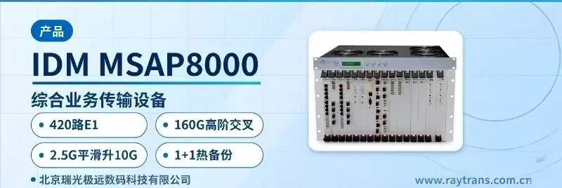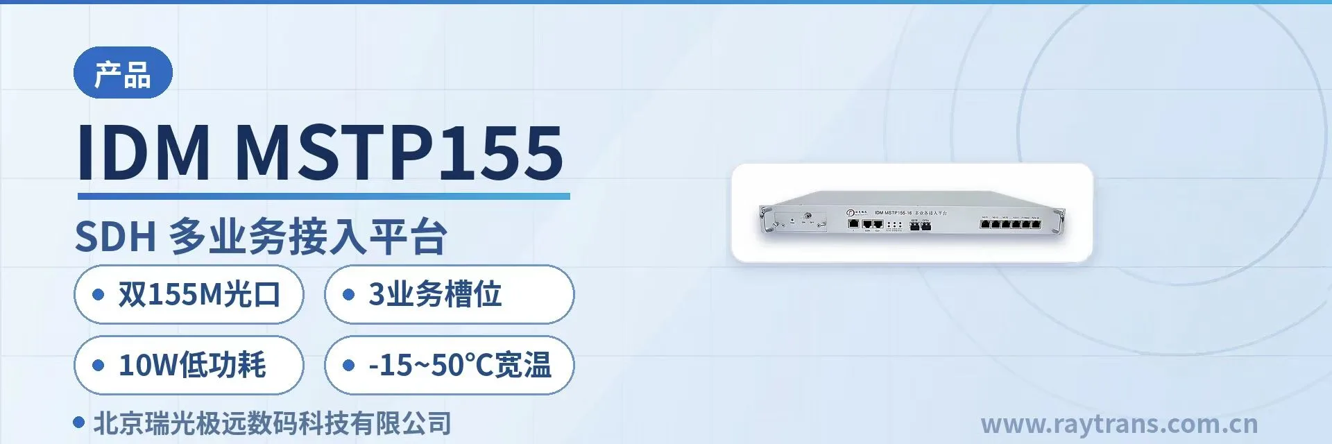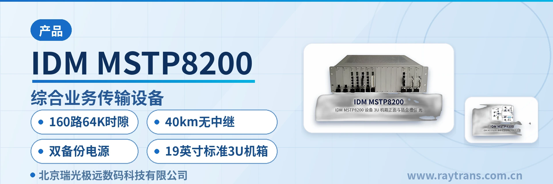
IDM MSTP8200 Integrated Service Transmission Equipment
15 3U card slots, 160 channels of 64K time slot services, VC12 full cross-connect 617
An integrated service transmission equipment with a 19-inch standard 3U chassis and card-based design, providing 15 3U user card slots and supporting STM-16/STM-4/STM-1 optical interfaces, SDH ring/chain networks, full cross-connect of TDM services, and access to various voice and data services.
The IDM MSTP8200 VC12 full cross-connect SDH transmission equipment is an integrated service transmission equipment developed by Beijing Ruiguang Jiyuan Digital Technology Co., Ltd. (Raytrans). It consists of a 19-inch standard 3U card-based chassis, SFP-type STM-16/STM-4/STM-1 optical interface units, a TDM full cross-connect unit, and various service access cards. It is used for voice and data service access, cross-connection, and transmission in electric power and energy private networks, rail transit and railway communications, and military and government private networks. As a mature SDH equipment, this product is widely used in government private network optical fiber communication solutions, military emergency communications vehicle solutions, and smart mining communication solutions, fully demonstrating Raytrans's technical accumulation in the field of optical transmission equipment.
The equipment performs full TDM service cross-connection with VC12 full cross-connect at 6174×6174, supports 160 channels of 64K time slot service access per standalone unit, and, combined with 40 km repeaterless transmission over STM-16/STM-4/STM-1 SFP optical interfaces, 1+1 tributary path protection, and AC/DC dual backup power supply, is suitable for long-term online operation at unattended sites. With its solid product showcase performance, this SDH equipment has become the preferred solution among many SDH equipment manufacturers.
Key specifications at a glance: 6174×6174 cross-connect · 160 channels of 64K time slots · 40 km repeaterless · dual backup power supply (SFP-type STM-16/STM-4/STM-1 optical interfaces · 19-inch 3U chassis with 15 3U user card slots · EoS physically isolated Ethernet · overall power consumption ≤150 W)
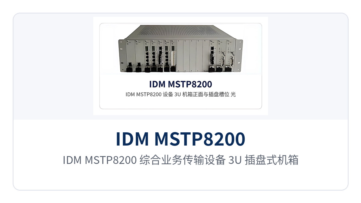
Figure 1: Front overall appearance of the IDM MSTP8200 Integrated Service Transmission Equipment 3U card-based chassis and user card slot layout
What Kind of Device Is a VC12 Full Cross-Connect SDH Transmission Equipment?
The IDM MSTP8200 VC12 full cross-connect SDH transmission equipment is an STM-N level multi-service SDH optical transmission system designed according to the functional modules defined in ITU-T G.783. It consists of SFP-type STM-16/STM-4/STM-1 optical interfaces, a VC12 cross-connect unit, a clock unit, and service access cards. The unit adopts a 19-inch standard 3U chassis and card-based design, and can serve as an add-drop multiplexer (ADM) or terminal multiplexer (TM) to form point-to-point and point-to-multipoint chain and ring transmission networks. As a professional SDH equipment, this product has broad application prospects in the field of optical transmission equipment. With years of technical accumulation, Raytrans continues to provide reliable product showcases and communication solutions for various industries.
The chassis provides 15 3U user card slots and can accommodate 3U plug-in boards such as the 3UMPCONV user optical port expansion card and the WG300 signaling exchange card, of which 10 user slots are used for various service cards. The service cards can access voice and data services such as PDH, E1, FXO/FXS, V.24/V.28/V.35, E&M 2/4-wire, hotline phone, magneto telephone, high-fidelity audio, X.50, and 10M/100M Ethernet, configured according to the project service list; when the network is expanded or the service type changes, service cards can simply be added or replaced, while the chassis and backplane continue to be used, and the number of equipment room racks and associated cables is reduced accordingly. This SDH equipment can flexibly adapt to various application scenarios such as government private network optical fiber communication solutions, military emergency communications vehicle solutions, and smart mining communication solutions.
How to Configure Service Cards in 15 3U Card Slots
To configure service cards in 15 3U card slots, the approach is to first determine the service types according to the site service list and then determine the number of cards. Voice services are carried by the 5-in-1 2-wire audio card 3U-8MVOICE, each card providing 8 channels of 2-wire audio, and each 2-wire audio channel can be configured as FXO, FXS, hotline, magneto, or 2100 magneto mode; data services are carried by E1 cards, codirectional 64K cards, and V.24/V.28/V.35 cards; when optical directions or signaling exchange need to be expanded, the 3UMPCONV user optical port expansion card and the WG300 signaling exchange card are inserted.
First count the number of voice channels, data channels, and audio channels at the site, and convert them into the number of each type of service card.
Then check the occupancy of the 10 user slots and 15 3U card slots, reserving slots for subsequent capacity expansion.
For special services such as radar data, the radar data access card can be inserted, each card providing 4 radar data service interfaces and supporting synchronous and asynchronous operating modes.
When the number of Ethernet interfaces needs to be expanded, use it together with the 8FE card.
How Are 160 Channels of 64K Time Slot Services Accessed per Standalone Unit?
The access path for 160 channels of 64K time slot services per standalone unit is as follows: various service cards access user signals, and after the services enter the equipment they are uniformly split into 64K time slots, which are assigned to the target optical direction in the VC12 cross-connect matrix according to site affiliation, with a single unit supporting 160 channels of 64K time slot service access.
Voice, data, and audio services share the same cross-connect matrix, so the access layer does not need to configure a separate narrowband multiplexer for each service, and the number of devices requiring separate maintenance and the variety of spare parts are reduced accordingly. During access planning, first count the number of voice, data, and audio channels by site, then check the number of service cards and slot occupancy, to avoid rework after commissioning due to insufficient slots or time slots.
What Are the Core Functions of the VC12 Full Cross-Connect SDH Transmission Equipment?
The IDM MSTP8200 integrates SDH optical transmission, TDM full cross-connect, and multi-service access in the same chassis. The functions and their descriptions are shown in the table below.
Function | Description |
|---|---|
Card-based chassis structure | 19-inch standard 3U chassis, card-based design, providing 15 3U user card slots |
SFP-type STM-16/STM-4/STM-1 optical interfaces | Provides optical interfaces at three rates of 2.5G, 622.08Mbps, and 155.52Mbps, supporting SDH ring and chain networking and 1+1 tributary path protection |
Full cross-connect of TDM interface services | VC12 cross-connect capacity 6174×6174, VC3 granularity 288×288, VC4 granularity 128×128, supporting unidirectional, bidirectional, and broadcast services |
160 channels of 64K time slot access | A single unit supports access of 160 channels of 64K time slot services, with voice, data, and audio services carried on the same platform |
Physically isolated EoS Ethernet | Provides physically isolated EoS Ethernet, with each group's bandwidth configurable by VC4 (N=1 |
5-in-1 2-wire audio card | The 3U-8MVOICE provides 8 channels of 2-wire audio per card, each channel configurable as FXO/FXS/hotline/magneto/2100 magneto mode |
Radar data access card | Each card provides 4 radar data service interfaces, supporting synchronous and asynchronous operating modes |
Clock source selection | The clock source can be selected as line clock, external clock (2Mbit/s or 2MHz), or free-run |
Service and signaling expansion cards | Can insert the 3UMPCONV user optical port expansion card and the WG300 signaling exchange card |
Ethernet management channel | Ethernet management channel based on DCC, E1, N*64K, and TCP/IP, providing the SNMP simple network management protocol |
Dual backup power supply | DC-48V and AC220V power supply, with optional DC+DC, AC+AC, and AC+DC dual backup power supply |
Technical Specifications of the VC12 Full Cross-Connect SDH Transmission Equipment
The E1 interface of the IDM MSTP8200 complies with ITU-T G.703, the Ethernet interface complies with IEEE802.3, the audio interface uses A-law companding per ITU G.711, and the V.24 and V.35 interfaces comply with CCITT V.28 and ITU-T V.35 recommendations respectively. The following parameters are taken from the public technical documentation of this VC12 full cross-connect SDH transmission equipment; the specific configuration is subject to the SDH equipment manufacturer's technical documentation and commercial confirmation.
Optical Interface Parameters
Item | Parameter/Specification | Description/Applicable Conditions |
|---|---|---|
STM-16 optical interface | SFP, receive/transmit rate 2.5G, single-mode, 1310nm/1550nm | Transmit power -12~-6dBm, receiver sensitivity better than -32dBm |
STM-4 optical interface | SFP, receive/transmit rate 622.08Mbps, single-mode, 1310nm/1550nm | Transmit power -12~-6dBm, receiver sensitivity better than -32dBm |
STM-1 optical interface | LC, receive/transmit rate 155.52Mbps, single-mode, 1310nm/1550nm | Transmit power -12~-6dBm, receiver sensitivity better than -32dBm |
Repeaterless transmission distance | 40km repeaterless | Standard model; can be customized when over 40km; long-distance module optional |
Service Interface Parameters
Item | Parameter/Specification | Description/Applicable Conditions |
|---|---|---|
E1 interface | Bit rate 2.048Mbps, line coding HDB3, impedance 75Ω/120Ω | Compliant with ITU-T G.703, frame structure PCM30/32, channel-associated signaling |
Ethernet (FE) | RJ-45, transmission rate N×VC12 (N≤50) | Supports IEEE802.3, full/half duplex/adaptive |
Ethernet (GE) | RJ-45, transmission rate N×VC12 (N≤63) | Supports IEEE802.3, full/half duplex/adaptive |
FXO, FXS interfaces | Audio range 300Hz~3400Hz, compression ITU G.711 A-law | Three-element complex impedance 200Ω+560Ω//0.1μF, loop current 20mA/channel |
Codirectional 64K interface | Line coding G.703 standard, bit rate 64Kbps, impedance balanced 120Ω | Compliant with ITU-T G.703 recommendation |
E&M 2/4-wire interface | Audio range 300Hz~3400Hz, impedance balanced 600Ω | Compression ITU G.711 A-law, return loss no less than 18dB |
Magneto interface | Audio range 300Hz~3400Hz, impedance balanced 600Ω | Compression ITU G.711 A-law, return loss no less than 18dB |
V.24 interface | Transmission rate asynchronous ≤9600bps; synchronous 64Kbps | Electrical characteristics compliant with CCITT V.28 protocol |
V.35 interface | RJ-45, transmission rate n×64Kbps (n=0~31) | Electrical characteristics compliant with ITU-T V.35 recommendation, terminal interface compliant with ISO2593 |
Figure 2: Close-up of the rear panel service interfaces and AC/DC power terminals of the IDM MSTP8200 Integrated Service Transmission Equipment
Unit Parameters
Item | Parameter/Specification | Description/Applicable Conditions |
|---|---|---|
Cross-connect capacity | VC12 6174×6174, VC3 288×288, VC4 128×128 | Full cross-connect between TDM interface services, supporting unidirectional, bidirectional, and broadcast services |
64K time slot access capacity | A standalone unit supports 160 channels of 64K time slot service access | 64K narrowband dedicated lines allocate time slots as required by the site |
Chassis structure | 19-inch standard 3U chassis, card-based design, 15 3U user card slots | 10 user slots for service cards, overall dimensions 480mm308mm131mm |
Clock source | Line clock, external clock (2Mbit/s or 2MHz), free-run | Selected according to networking conditions |
Power supply mode | AC220V/DC-48V | Optional DC+DC, AC+AC, AC+DC dual backup power supply, overall power consumption ≤150W |
Operating environment | Operating temperature -10℃ | Suitable for both equipment room and industrial site cabinet environments |
How to extend the 40km repeaterless STM-16 optical interface
To extend the 40km repeaterless STM-16 optical interface, first measure the actual distance between sites and the optical cable attenuation, then select the optical module according to the distance grade. The standard model has a repeaterless transmission distance of 40 km. Beyond 40 km, it can be customized, or a long-distance module can be installed to achieve longer optical fiber transmission, thereby reducing the number of repeater stations and the investment in supporting power supplies and cabinets.
Match the rate step to the station distance and service volume: for long-distance ring networks with larger station spacing and concentrated services, use the STM-16 optical interface (2.5G); for sections with shorter station spacing and smaller service volume, STM-4 (622.08Mbps) or STM-1 (155.52Mbps) optical interfaces are sufficient, avoiding excess rate and investment. The model and supported distance of the long-distance module should be technically confirmed with the SDH equipment manufacturer according to the project.
How to schedule 64K time slots with 6174×6174 cross-connect
VC12 full cross-connect 6174×6174 means that any accessed 64K time slot can be scheduled to any target optical direction without being restricted by other connections. The scheduling route is: the 64K services of each user slot first enter the cross-connect matrix, are configured to the corresponding STM-N tributary according to site affiliation, and the opposite end device restores them to the user interface. Voice channels and data dedicated lines are allocated as required within the ring network.
When adding a site or adjusting service assignment, only the cross-connect configuration is changed, while the external optical cable and user-side wiring remain unchanged, resulting in low on-site workload. The VC3 granularity 288×288 and VC4 granularity 128×128 cross-connect capacity provide dispatching resources for broadband services such as Ethernet, sharing the same matrix with the narrowband dispatching of VC12.
How to expand a 3U card-based SDH transmission device
How to expand a 3U card-based SDH device — the answer is to keep the chassis and backplane in use and simply add or replace service cards according to service growth. IDM MSTP8200 service cards are configured according to the project service list. When a site adds telephone, data, or audio services, first check the remaining capacity of the 10 user slots and 15 3U card slots, then insert the corresponding service cards. When optical directions are insufficient, insert the 3UMPCONV user optical port expansion card; when Ethernet interfaces are insufficient, use them together with the 8FE card.
Another type of expansion comes from bandwidth: Ethernet services can be reassigned among VC4 (N=18), VC3 (N=124), and VC12 (N=1~50) granularities for each group of EoS bandwidth. The cross-connect matrix reallocates 64K time slots within the VC12 6174×6174 range, without replacing the entire unit or modifying external optical cables. The expansion plan should be confirmed with the SDH equipment manufacturer based on the project service list and redundant slot planning.
How AC/DC dual backup power supply adapts to unattended sites
How AC/DC dual backup power supply adapts to unattended sites relies on the mutual backup of the main and standby power feeds, where one feed continues supplying power when the other is abnormal. The device power supply mode is AC220V or DC-48V, with optional DC+DC, AC+AC, AC+DC dual backup power supply, and overall power consumption ≤150W. Combined with tributary 1+1 path protection, the site retains available channels when a single power feed or a single fiber segment is abnormal.
Sites with only a DC distribution panel: choose DC+DC dual backup, with two DC power feeds introduced separately.
Sites with only mains power: choose AC+AC dual backup, with two AC power feeds introduced separately.
Sites with both DC and mains power: choose AC+DC dual backup, with AC and DC backing up each other, unifying spare parts and O&M practices.
The specific configuration of the dual backup power supply should be confirmed with the SDH equipment manufacturer based on the actual power supply conditions of the equipment room.
Differentiated value: 6174×6174 cross-connect · 160 channels of 64K time slots · 40km repeaterless · dual backup power supply
As a mature SDH device, the Raytrans IDM MSTP8200 showcases three differentiated capabilities that each address a real-world problem at the private network access layer.
Differentiation Point | Customer Value |
|---|---|
VC12 full cross-connect 6174×6174, a standalone unit supports 160 channels of 64K time slot service access | Voice, data, and audio services are uniformly dispatched within a single unit, so the access layer does not need a separate narrowband multiplexer for each service type, reducing the number of racks and cables |
STM-16/STM-4/STM-1 SFP optical interfaces, 40km repeaterless, optional long-distance module | Line corridors with larger station spacing require fewer repeater stations, reducing investment in supporting power supplies and cabinets; beyond 40km, a long-distance module can be installed as required |
AC/DC dual backup power supply + tributary 1+1 path protection, suitable for unattended sites | Key services still have available channels when a single power feed or a single fiber segment is abnormal, and sites with different power supply conditions can use the same model |
Typical application scenarios
Electric power and energy private network
In an electric power and energy private network, the Raytrans IDM MSTP8200 VC12 full cross-connect SDH device is deployed at the access layer between substations, switching stations, and the dispatch center, forming an SDH ring network at an STM-16 optical interface rate of 2.5G, with 40km repeaterless coverage for line corridors with larger station spacing. Dispatch voice is carried by the 5-in-1 2-wire audio card, with the FXS side connected to dispatch telephones and the FXO side connected to switching equipment; magneto mode adapts to existing magneto telephones. Protection information and monitoring data are allocated channels by 64K time slots, sharing the same cross-connect matrix with voice. Tributary 1+1 path protection and AC/DC dual backup power supply keep communications at unattended substations available when a single fiber segment or a single power feed is abnormal.
Rail transit and railway communications
In rail transit and railway communications, the IDM MSTP8200 accesses the transmission network of stations along the line, depots, and traction substations via STM-4/STM-1 optical interfaces, carries services such as signal interlocking and blocking through E1 interfaces, and completes per-station allocation of 64K time slots along the line through VC12 full cross-connect. Train dispatching telephones and section official telephones can be enabled with one 5-in-1 2-wire audio card configured for multiple lines, and hotline and magneto modes adapt to existing railway telephone types. After inter-station services are concentrated into one 3U device, the number of devices and cables in equipment rooms along the line is reduced, and the network management system incorporates them into unified road network monitoring via SNMP.
Military and government private network
In a military and government private network, the IDM MSTP8200 is installed in the rack of an emergency communications vehicle in a 3U card-based chassis. Its 15 3U user card slots allow one unit to mix E1, audio, radar data, and physically isolated Ethernet services, enabling rapid card configuration and networking according to the on-site service list. The radar data access card provides 4 radar data service interfaces per card; voice is accessed via the 5-in-1 2-wire audio card; EoS Ethernet bandwidth is assigned at VC4, VC3, or VC12 granularity and is isolated from production data at the hardware layer. AC/DC dual backup power supply and tributary 1+1 path protection keep the emergency communications vehicle and field sites communicating when power supply and fiber conditions change.
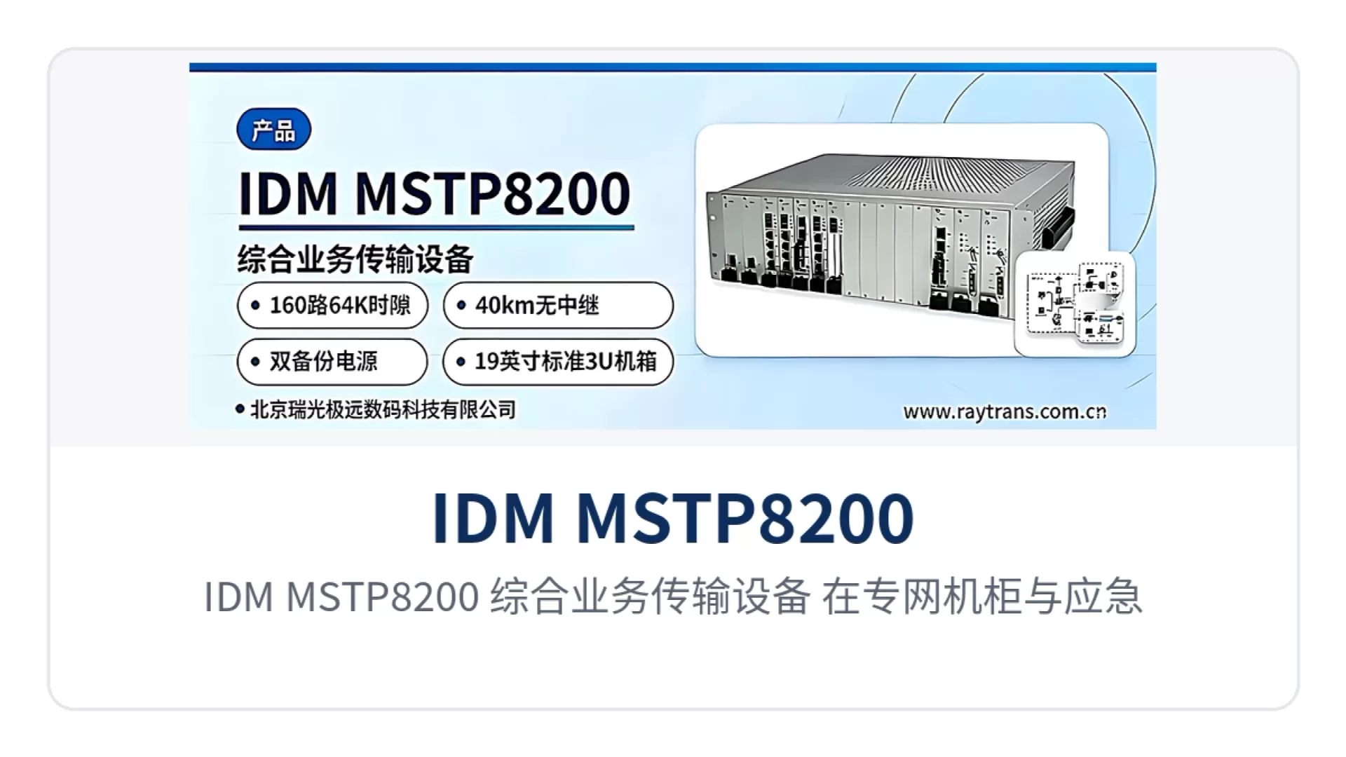
Figure 3: Installation and networking diagram of the IDM MSTP8200 Integrated Service Transmission Equipment in a private network cabinet and an emergency communications vehicle