IDM MAP4E1
IDM MAP4E1
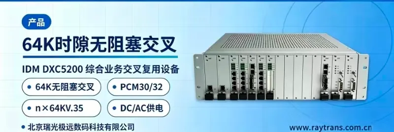
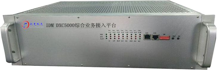
The IDM MAP4E1 4xE1 Line Mutual Backup PCM Equipment uses 2M cable as the transmission medium and provides 4 E1 transmission channels externally; the 1st and 2nd E1 support 1+1 protection switching, and the 3rd and 4th E1 support 1+1 protection switching. Supports point-to-point transmission and point-to-multipoint transmission.
Overview
The IDM MAP4E1 4xE1 Line Mutual Backup PCM Equipment uses 2M cable as the transmission medium and provides 4 E1 transmission channels externally; the 1st and 2nd E1 support 1+1 protection switching, and the 3rd and 4th E1 support 1+1 protection switching. Supports point-to-point transmission and point-to-multipoint transmission.
The IDM MAP4E1 4xE1 Line Mutual Backup PCM Equipment features 15 universal user interface slots, with each card providing 2 channels of 64K service access, supporting a maximum of 30 channels of 64K service at full configuration.
The network management transmission channel of the IDM MAP4E1 4xE1 Line Mutual Backup PCM Equipment supports transmission via the TS0 timeslot Sa bits or via any designated timeslot from TS1 to TS31. This enables monitoring of the status of all network equipment.
Different service cards can be configured to meet various user service requirements.
The configurable service cards include:
Ø 10/100Base-T Ethernet interface card
Ø Ordinary telephone cards with polarity reversal and caller ID functions (FXO, FXS);
Ø EM 2/4-wire audio card;
Ø Hotline telephone card with standard signaling tones;
Ø Ordinary magneto telephone card;
Ø 2100Hz magneto carrier trunk card;
Ø V.24/V.28 card (RS232/RS485);
Ø ITU G.703 64K co-directional data card;
Ø X.50 sub-rate multiplexing card.
Ø K-interface access card, supporting four transmission rates: 16Kbit/s, 32Kbit/s, 64Kbit/s, and 128Kbit/s.
It can be widely applied in air traffic control, telecommunications data services, electric power, banking, public security, military and other sectors for public switched telephone network access or dedicated line information transmission.

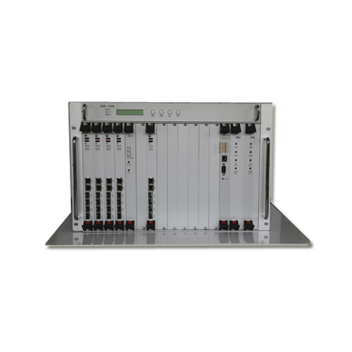
IDM MAP4E1-30 E1 Line Mutual Backup PCM Equipment Front Panel Diagram
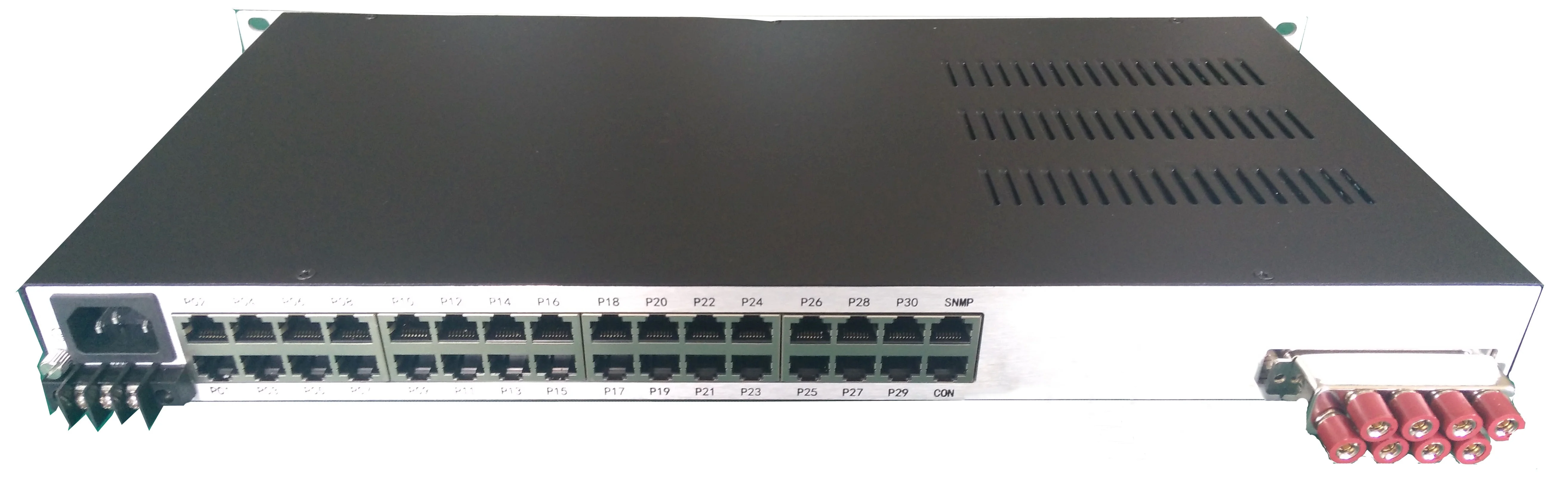
IDM MAP4E1-30 E1 Line Mutual Backup PCM Equipment Rear Panel Diagram
Main Features
(1) A single chip completes the transmission signal processing of 4 E1 lines, greatly improving the long-term stability of the equipment;
(2) Provides E1 line transmission and reception in four transmission directions, facilitating the formation of complex ring and star networks, or optionally providing 1+1 protection switching for one group of E1 ports;
(3) Supports overcurrent and overvoltage protection for voice interfaces, and supports E1 upstream/downstream pass-through in the event of equipment power failure;
(4) The E1 interface line code type is HDB3 code. The E1 jitter tolerance, transfer characteristics, and output jitter fully comply with ITU-T G.703, G.706, G.823, and G.742 recommendations;
(5) The E1 interface supports BNC or RJ-48C interface connectors;
(6) Adopts a 19-inch 1U standard chassis, providing up to 30 user interfaces. Users can freely configure more than 20 types of interface cards;
(7) Features two equipment clock modes. Master clock and line clock modes can be set to meet various application environments.
Ø Master clock: uses the local clock
Ø Line clock: line clock recovered from the 1st to 4th E1 lines
(8) Built-in 256*256 timeslot cross-connect matrix. Enables data and signaling cross-connection between user-to-user, user-to-line, and line-to-line. Therefore, this unit can also be used as a timeslot cross-connect equipment for 4 E1 lines;
(9) Provides 15 user interface slots. Each slot can accommodate a 2-channel single-timeslot card. Currently available user card types include central office card (FXO), remote card (FXS), hotline telephone card, magneto telephone card, 2100Hz carrier trunk card, V.24 card (RS232/RS485), co-directional card (G.703), as well as EM 2/4-wire audio card, ordinary audio card, Ethernet card, V.35 card, K-interface card, etc.;
(10) Provides RS232 network management interface and IP network management interface. Supports restoring the network management IP to default configuration by pressing and holding the MASK button for more than 5 seconds;
(11) Supports DIP switch functions for quick configuration of equipment clock, operating mode, E1 loopback, station address, and other functions;
(12) Features concise and comprehensive network management functions. Supports equipment configuration, query, fault location, alarm query, timeslot reallocation, and other configuration functions;
(13) Supports online upgrade of the equipment underlying program;
(14) The front panel features comprehensive function control switches and alarm sound muting capability, displaying alarm indication information for each E1 line including master/slave clock (CLK), loss of signal (LOS), loss of frame (LOF), alarm indication signal (AIS), remote alarm indication (RAI), etc., with push-button switches to select whether to mute the alarm tone;
(15) Complies with ITU-T G.703, G.704/98, G.706, and G.732 protocols, serving as multiplexing equipment for PCM base groups;
(16) Powered by AC 220V power supply or DC -48V power supply;
(17) Total output power: ≤10 W (per complete unit).
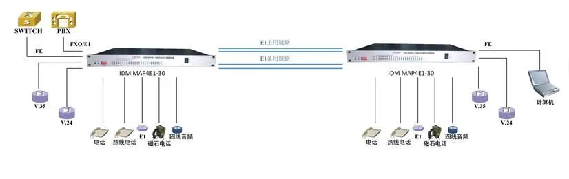
Typical Application
FAQs
What is the working principle of Pulse Code Modulation (PCM)?
Working Principle Pulse Code Modulation is the process of converting a time-continuous…
View answerPCM30 Working Principle: What Is PCM30/32
PCM30 Equipment Working Principle The 30-channel PCM equipment refers to equipment that provides 30 user interfaces and…
View answerWhat are the common problems of PCM equipment in enterprise applications?
At present, PCM equipment has become basically ubiquitous in enterprise network applications.
View answerWhat is E1? How to Use E1
What is E1 The European 30-channel pulse code modulation PCM is abbreviated as E1, with a rate of 2.048Mbit/s.
View answerFrame Structure of 30/32-Channel PCM Primary Group
A communication system consists of transmitting equipment, receiving equipment, and transmission equipment.
View answer