IDM GP2400-8E1-30 Integrated Service Optical Multiplexer
30-channel voice, 8E1, dual gigabit, four Fast Ethernet physically isolated, single-fiber receiving port saves three devices
The IDM GP2400-8E1-30 gigabit network optical multiplexer features 2.5G optical interfaces and provides up to 30 voice access channels, 8 E1 channels, 2 physically isolated line-rate 1000M Ethernet interfaces and 4 physically isolated line-rate 100M Ethernet interfaces over optical fiber, along with a standard SNMP network management interface.
IDM GP2400-8E1-30 is a 30-channel voice 8E1 dual-gigabit optical multiplexer developed by Beijing Raytrans, a PDH product showcase solution for multi-service scenarios that carries telephone voice, 8 E1 leased lines, 2 gigabit and 4 Fast Ethernet services over a single optical fiber link. The device uses 2.5G SFP optical interfaces and the PCM30/31 format, with one unit at each end operating in pairs, so that site-side services are restored as they are at the central equipment room to existing switching equipment and protection devices. As a combination of integrated service access device and optical multiplexing equipment, this model plays the role of unified voice and data transport in the product lineups of PCM equipment and optical multiplexer manufacturers, and can serve applications with high link reliability requirements such as government private network optical fiber communication solutions and military emergency communications vehicle solutions.
Key Specifications at a Glance: Optical port 2×SFP 2.5G (single-mode, multimode optional, 1310nm/1550nm, transmit optical power -1~-3dBm) · Receiver sensitivity better than -24dBm · Voice 30 channels (FXO/FXS/magneto, ITU G.711 A-law, loop current 25mA/channel) · E1 8 groups 2048Kbps HDB3 transparent transmission (ITU-T G.703, 75Ω/120Ω, PCM30/31) · Ethernet 2 isolated gigabit + 4 isolated Fast Ethernet · Power supply DC-48V/AC220V dual power supply · Overall power consumption ≤100W
What kind of device is the 30-channel voice 8E1 dual-gigabit optical multiplexer
The 30-channel voice 8E1 dual-gigabit optical multiplexer belongs to the category of integrated service optical multiplexing equipment, packing voice, E1 and Ethernet interfaces into the same optical path and replacing the telephone optical multiplexers, E1 optical modems and switch uplink equipment previously deployed separately. For private network projects with distributed sites and limited equipment room space, one device completes the product showcase-level consolidation, and cabling and spares are reduced accordingly.
The device's two 2.5G optical ports use pluggable SFP modules, with single-mode as standard and multimode optional, and dual-selectable 1310nm/1550nm wavelengths. In engineering practice, modules are selected according to fiber core conditions and line loss, and a single optical fiber link between a pair of end stations collects all 30 voice channels, 8 E1 groups and all Ethernet services; the optical ports can be configured with 1+1 protection, so that services are switched to the standby optical path when the primary path is interrupted.
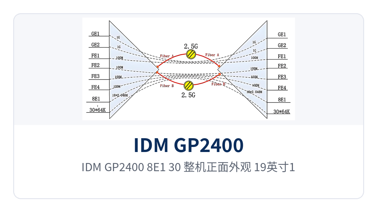
Figure 1: IDM GP2400-8E1-30 overall front appearance, 19-inch 1U chassis and front panel operating indicator LED layout
Which services can one device carry simultaneously
IDM GP2400-8E1-30 provides six categories of capabilities in one 1U device: optical fiber transmission, telephone voice, E1 transparent transmission, isolated Ethernet, dual power supply and SNMP network management. The function items and corresponding interface standards are listed in the table below, so that configuration adequacy can be confirmed row by row during project verification.
| Function | Description |
|---|---|
| 2.5G optical fiber transmission | Optical interface is SFP, rate 2.5G, single-mode (multimode optional), wavelength 1310nm/1550nm; one optical fiber link carries voice, E1 and Ethernet services simultaneously; the two optical ports can be configured with 1+1 protection |
| 30-channel voice access | Provides 30 telephone interfaces, configurable as FXO, FXS or magneto; audio range 300Hz~3400Hz; compression ITU G.711 A-law; loop current 25mA/channel |
| 8-channel E1 transparent transmission | Provides 8 E1 channels, bit rate 2048Kbps, HDB3 coding, supporting ITU-T G.703, impedance 75Ω/120Ω, frame structure PCM30/31; transparent transmission does not change time slot content |
| Isolated gigabit Ethernet | 2 physically isolated wire-speed 1000M interfaces, RJ45 form, transmission rate 10M/100M/1000M, compliant with IEEE802.3, full/half duplex/adaptive |
| Isolated Fast Ethernet | 4 physically isolated wire-speed 100M interfaces, each independently encapsulated, so that abnormal traffic on one channel does not affect the other channels |
| Dual power supply redundant power | Two pluggable power supply modules, supporting DC-48V and AC220V access, overall power consumption ≤100W; loss of one power feed does not affect service operation |
| SNMP network management and alarms | Provides a standard SNMP network management interface; the chassis is equipped with a function control switch and alarm indication, and the central equipment room can remotely check remote station status |
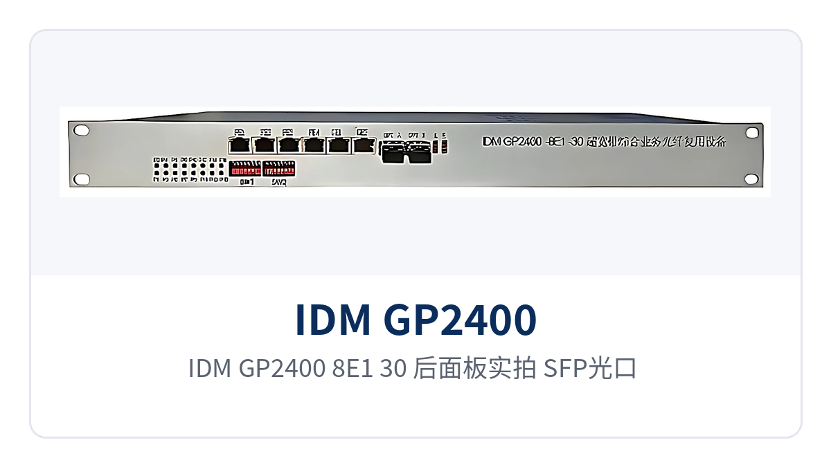
Figure 2: IDM GP2400-8E1-30 rear panel photo, SFP optical ports, E1 coaxial interfaces, isolated Ethernet ports and dual power supply terminals layout
How three types of services are packed into one 2.5G optical path
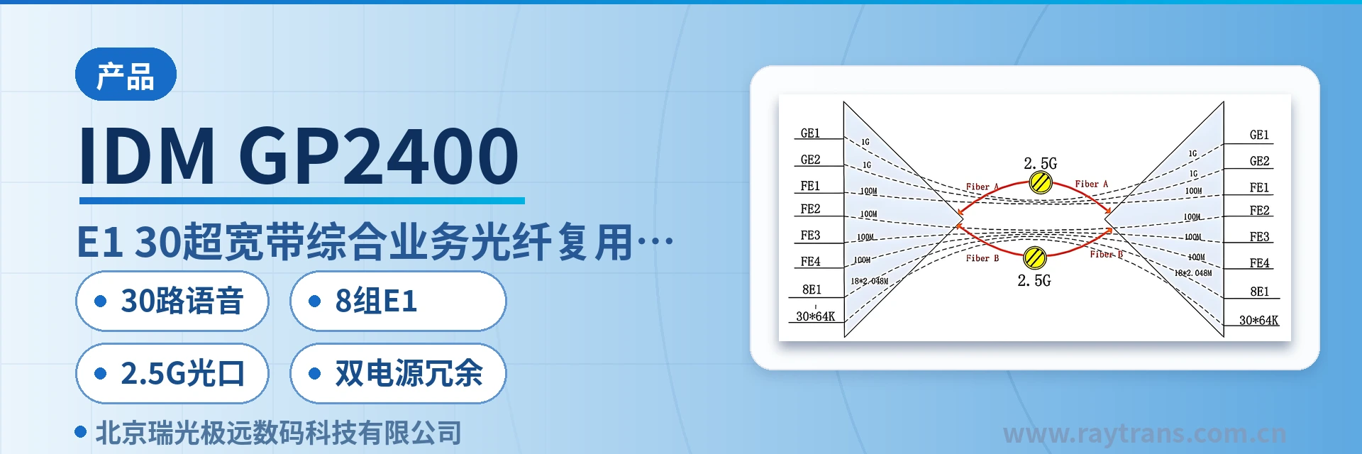
Voice, E1 and Ethernet each occupy an independent channel inside the device and do not change each other's encoding or frame structure. Voice is arranged into the primary group frame according to PCM30/31, E1 is transparently transmitted at 2048Kbps with HDB3, and Ethernet is independently encapsulated and then multiplexed onto the 2.5G optical path; the three types of services arrive at the peer station simultaneously without preempting each other's time slots.
This multiplexing approach lets one device do the work previously done by multiple single-function devices. Site-side interface types remain unchanged, and upper-level switching equipment usually does not need configuration adjustments; the modification workload is concentrated on installation of the devices at both ends and optical cable splicing, and service cutover can be completed in one planned window. As an integrated service access device under the PDH regime, this model is often used as the consolidation node for remote stations in government private network optical fiber communication solutions.
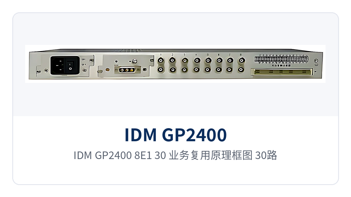
Figure 3: IDM GP2400-8E1-30 service multiplexing principle block diagram, 30 voice channels, 8 E1 groups and isolated Ethernet multiplexed onto the 2.5G optical port
Key Specifications
The technical specifications of IDM GP2400-8E1-30 are divided into six parts: optical interface, E1 interface, Ethernet interface, voice interface, power supply and environment. The values in the table below are subject to product documentation and factory testing, and should be reviewed item by item against the actual configuration during project calculation.
| Item | Parameter/Specification | Description/Applicable Conditions |
|---|---|---|
| Optical interface type | SFP | Pluggable optical module, easy to replace by distance and to spare |
| Fiber mode | Single-mode (multimode optional) | Selected according to line distance and fiber core conditions |
| Optical fiber rate | 2.5G | Shared by voice, E1 and Ethernet services |
| Wavelength | 1310nm/1550nm | Two wavelengths selectable |
| Transmit optical power | -1~-3dBm | Typical single-mode value; subject to actual measurement with an optical power meter |
| Receiver sensitivity | Better than -24dBm | The link loss budget can be calculated on this basis |
| E1 bit rate | 2048Kbps | HDB3 coding |
| E1 standard protocol | Supports ITU-T G.703 | Standard E1 interface specification |
| E1 impedance | 75Ω/120Ω | Selected according to the interface of the interconnected equipment |
| E1 frame structure | PCM30/31 | Primary group frame structure |
| E1 mode | Transparent transmission | Services are transmitted as they are, without changing time slot content |
| Ethernet interface type | RJ45 | 2 isolated gigabit and 4 isolated Fast Ethernet |
| Ethernet transmission rate | 10M/100M/1000M | Compliant with IEEE802.3, full/half duplex/adaptive |
| Voice audio range | 300Hz~3400Hz | Telephone voice channel bandwidth |
| Voice impedance | Three-element complex impedance 200Ω+560Ω//0.1μF | Telephone subscriber line interface standard |
| Voice compression | ITU G.711 A-law | 64Kbps PCM encoding |
| Voice loop current | 25mA/channel | Feeding capability of each voice channel |
| Power supply mode | DC-48V /AC 220V/dual power supply | Dual power supply access improves power supply reliability |
| Overall power consumption | ≤100W | Overall value including service cards and optical modules |
| Operating temperature | 0ºC~40ºC | Equipment room and temperature-controlled cabinet environments |
| Humidity | ≤90% (non-condensing) | Upper limit of relative humidity |
How the 2.5G optical port stays stable on weak-signal long-distance links
Link stability depends on the loss budget, not just the nominal rate. The 2.5G optical port has a transmit optical power of -1~-3dBm and a receiver sensitivity better than -24dBm, and the margin left between the two ends can cover the attenuation and splice point loss of longer single-mode links. The transmission distance is determined by the distance grade of the selected SFP module, subject to the manufacturer's technical documentation.
The on-site calculation practice is to first measure the received optical power with an optical power meter, then compare it with the -24dBm threshold, leaving a margin of more than 3dB to cope with aging and temperature changes. When the received optical power approaches the threshold, first clean the flange and patch cord end faces; if it is still insufficient, switch to a module with a higher power budget. For scenarios with more connectors, such as vehicle mobility and temporary optical cable deployment, the same method can be recalculated. Such optical multiplexing equipment undertakes rapid commissioning of voice and E1 services in military emergency communications vehicle solutions, and Raytrans, as an optical multiplexer manufacturer, has accumulated experience in on-site adaptation of PCM equipment and optical transmission products that can be directly applied to loss calculation for such links.
How dual power supply redundancy and 100W power consumption fit unattended equipment rooms
Dual power supply redundancy is achieved by feeding two independent power feeds to two pluggable power supply modules respectively, so that services are maintained by the other feed when either one fails. IDM GP2400-8E1-30 supports DC-48V and AC220V access; the -48V DC and 220V AC mains power commonly used in communications equipment rooms can each occupy one feed, and the overall power consumption is ≤100W, making capacity calculation for in-station UPS or solar power easier to pass.
Dual power supply access and commissioning are checked item by item in the following four steps, each corresponding to an on-site observable criterion; from checking the power supply type before power-on to verifying services one by one after power-on, a complete commissioning chain is formed, and subsequent maintenance can be rechecked in the same order to locate the problem.
- Before power-on, check the site power supply type against the device markings, and confirm that the -48V polarity and 220V terminal wiring are correct;
- Check the protective grounding and terminal crimping to avoid heating caused by loose connections;
- Draw the two power feeds from different distribution circuits to reduce the probability of simultaneous power loss;
- After power-on, observe the power supply and alarm indications, confirm normal received optical power, and then verify voice, E1 and Ethernet services one by one.
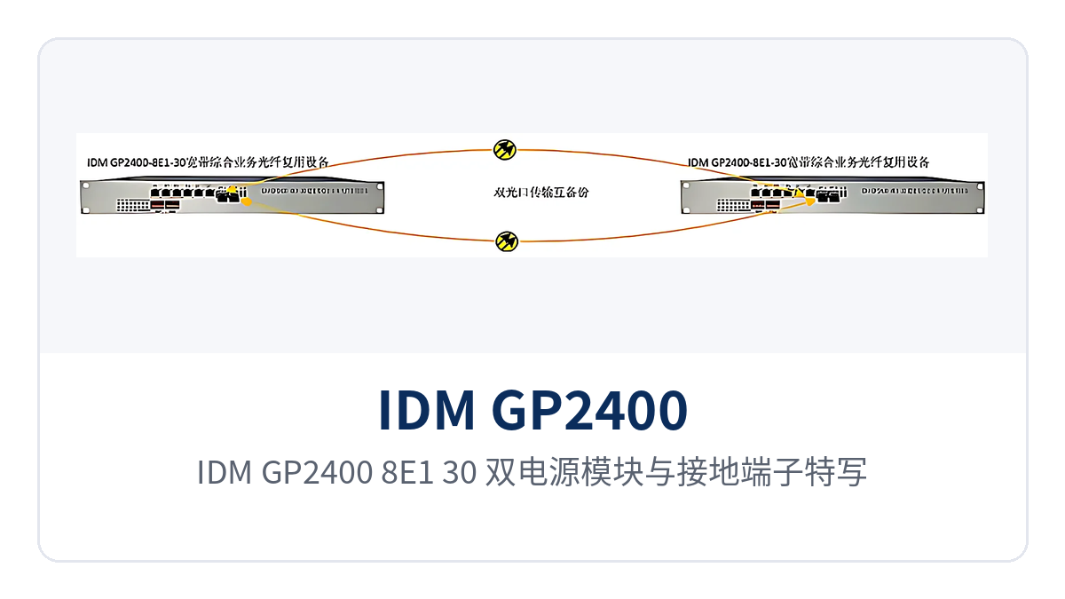
Figure 4: IDM GP2400-8E1-30 dual power supply modules and grounding terminals close-up, DC-48V and AC220V two independent feeds
Typical Application Scenarios
IDM GP2400-8E1-30 is mainly deployed in point-to-point mode, with one unit at each end interconnected by a single optical fiber link, and site-side services are restored at the central equipment room and then connected to existing transmission, switching and protection equipment. When a site is expanded, interfaces can simply be added without laying new optical cables, keeping construction and coordination costs within a controllable range. As a product showcase solution for private networks, the device has been deployed maturely in scenarios such as electric power, rail transit, military and government.
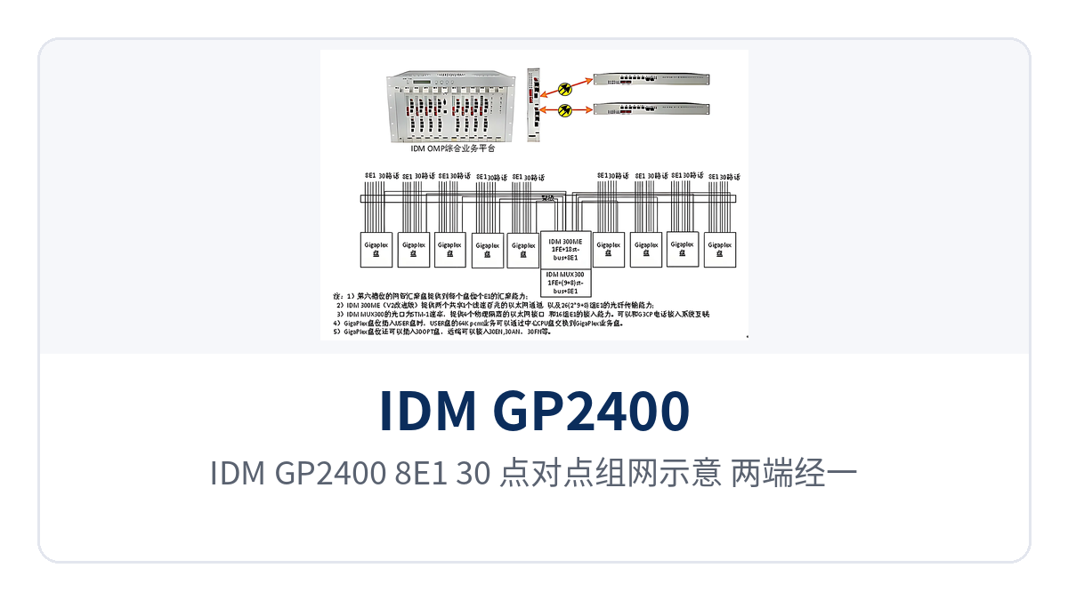
Figure 5: IDM GP2400-8E1-30 point-to-point networking diagram, both ends interconnected via a single 2.5G single-mode optical fiber and connected to the dispatching exchange
Electric power private network: unattended substations, one fiber carrying dispatch voice and automation E1
A substation and a dispatch station usually require dispatch telephone, automation E1 leased lines, and in-station data channels at the same time. IDM GP2400-8E1-30 is deployed one unit per site, multiplexing 30 channels of dispatch voice, 8 groups of E1, and Ethernet data over a single 2.5G single-mode optical fiber, so the equipment room no longer stacks telephone optical multiplexers, E1 optical modems, and standalone data transmission devices. This multi-service-over-one-fiber integrated service access device form effectively reduces equipment stacking and wiring workload in the equipment room.
Voice is encoded in A-law per ITU G.711 with a loop current of 25mA per channel, and can be directly connected to existing dispatch voice channel equipment; E1 is transparently transmitted at 2048Kbps with HDB3 and PCM30/31, and the dispatching exchange and relay protection devices at the opposite end require no configuration changes. With DC-48V and AC220V dual power supply access, services remain available when a single power supply fails.
Rail Transit: Weak-Light Long-Distance Sections, 8 E1 Channels Transparently Transmitted to Guarantee Train Operation and Dispatch Voice
Distances between stations, depots, and section equipment rooms are long with many splice joints, so received optical power is often low. The 2.5G optical port offers receiver sensitivity better than -24dBm and still receives optical signals normally under weak-light conditions; combined with 1310nm/1550nm dual-wavelength modules selected according to section loss, it reduces repeated adjustment caused by link attenuation.
Train operation telephone and dispatch voice run over PCM30/31 voice channels, and the 8 E1 channels are transparently transmitted with 75Ω/120Ω configuration per ITU-T G.703, so existing signaling and dedicated communication equipment need no configuration changes. 2 physically isolated gigabit and 4 physically isolated Fast Ethernet ports directly connect to in-station switches and the surveillance network, and physical isolation keeps abnormal traffic on one channel from affecting other channels.
Military and Government Private Networks: Dual Power Supply Redundancy and SNMP Network Management, Lightly Staffed Remote Sites
Remote sites of military, government, and political and legal systems are often lightly staffed, with limited power supply and on-site maintenance conditions. The device provides dual power supply redundancy and pluggable power supply modules, with overall power consumption ≤100W, and can be deployed in a temperature-controlled cabinet as a 19-inch 1U chassis; the SNMP network management interface lets the central equipment room check remote status remotely, reducing the frequency of on-site inspection. In a government private network optical fiber communication solution, the device can serve as a remote access node and work with existing transmission equipment in the central equipment room for networking; for a military emergency communications vehicle solution, its 1U chassis and dual power supply design also facilitate rapid deployment in the communication vehicle cabinet.
E1 interfaces on the private network side are mostly 75Ω coaxial or 120Ω balanced interfaces, and the device supports both impedances; with ITU-T G.703 and PCM30/31 transparent transmission, it can be directly connected to existing PCM equipment and private network switches. Operating temperature 0ºC–40ºC and humidity ≤90% (non-condensing) suit standard equipment rooms and communication vehicle cabinet environments.
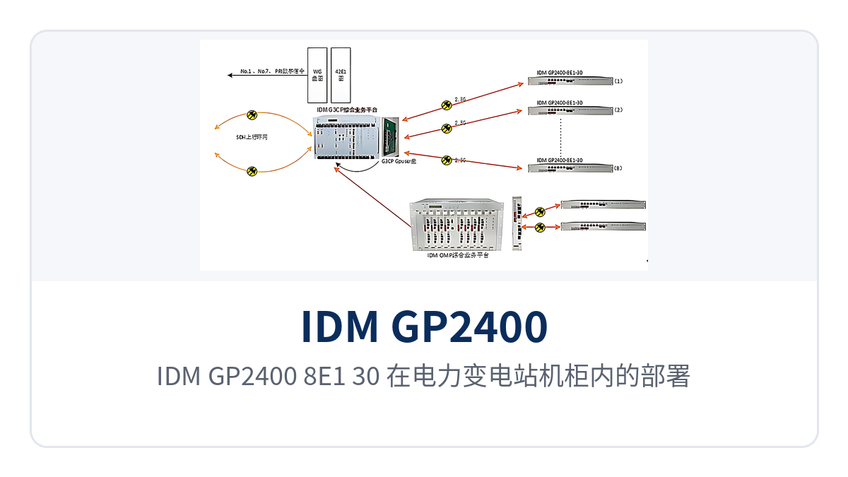
Figure 6: Actual deployment of IDM GP2400-8E1-30 in an electric power substation cabinet, with 2.5G optical fiber uplink and voice wiring in parallel
Differentiated Value: Multi-Service over One Fiber, 8 E1 Groups, and Isolated Ethernet
The differentiation of IDM GP2400-8E1-30 centers on four points: multiple service types over one fiber, 8 E1 groups, 2 gigabit plus 4 Fast Ethernet isolated ports, and 2.5G optical ports with dual power supply redundancy. The correspondence between these four capabilities and the actual value for private network customers is shown in the table below, facilitating selection according to project pain points.
| Differentiation Point | Specific Capability | Value for Private Network Customers |
|---|---|---|
| Multi-service over one fiber | One optical fiber link simultaneously carries 30 channels of voice, 8 E1 groups, 2 gigabit and 4 Fast Ethernet ports | A site needs only one pair of devices and one optical cable, reducing equipment stacking and wiring workload in the equipment room |
| 8 E1 groups transparent transmission | 8 E1 groups transparently transmitted at 2048Kbps with HDB3 and PCM30/31, supporting ITU-T G.703 | Existing relay protection, dispatching exchange, and PCM equipment can be connected without configuration changes |
| Isolated Ethernet | 2 wire-speed gigabit and 4 wire-speed Fast Ethernet physically isolated ports, each encapsulated independently | Surveillance, office, and production data are carried separately, and an abnormality on one channel does not affect other channels |
| 2.5G optical ports and dual power supply redundancy | SFP 2.5G optical ports with receiver sensitivity better than -24dBm; DC-48V/AC220V dual power supply, overall power consumption ≤100W | Stable optical reception on weak-light long-distance links, and services continue when one power supply fails at an unattended site |