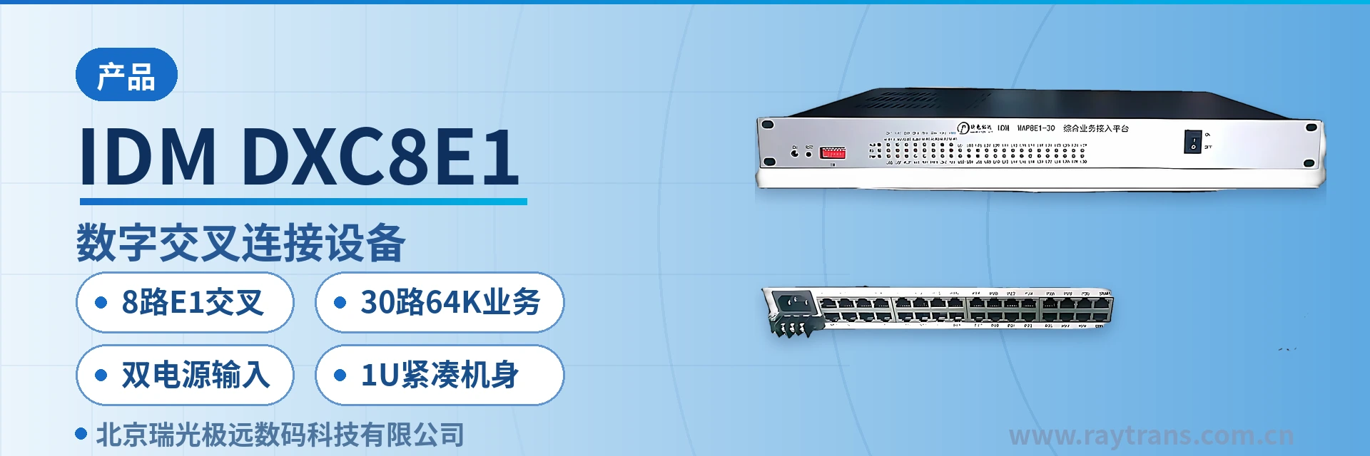
IDM DXC8E1 Digital Cross-Connect Equipment
Cross-connect pushed down to the access layer, 8-channel E1 non-blocking, 30-channel 64K mixed traffic, card replacement without rewiring
The IDM DXC8E1 digital cross-connect equipment is an integrated service platform that combines 64 kbit/s narrowband service access, PCM multiplexing, and 64K time-slot cross-connection. The IDM DXC8E1 is mainly used for service access and cross-connection at the access layer of data communication networks. It provides complete synchronous timing functions and non-blocking cross-connection at 64K granularity across 8 E1 channels, and can also provide 30 channels of 64 kbit/s services, including telephone, magneto telephone, common battery telephone, and V.24 data services.
The IDM DXC8E1 digital cross-connect equipment is an 8-channel E1 digital cross-connect device developed by Beijing Ruiguang Jiyuan Digital Technology Co., Ltd. (Raytrans) for service access and cross-connection at the access layer of data communication networks. As a PCM equipment designed for the access layer, it integrates 64K narrowband service access, PCM multiplexing, and 64K time-slot cross-connection in a compact 1U chassis, providing 64K-level non-blocking cross-connection across 8 E1 channels while accessing 30 channels of 64K services. Its PCM multiplexing capability and compact structure give the device high port utilization in integrated service access device scenarios.
Key Specifications at a Glance: 8-channel E1 non-blocking cross-connection · 30-channel 64K service access · 15 service card slots · AC 220 V/DC -48 V dual power input · PCM30/32 channel-associated signaling · compact 1U chassis
The service mix at an access-layer node is usually complex: dispatch telephones, magneto telephones, common battery telephones, and telecontrol data coexist, while the time slots available on each E1 channel are limited. Telephone, magneto telephone, common battery telephone, and V.24 data services are carried together in the IDM DXC8E1 digital cross-connect equipment, uniformly split into 64K time slots and allocated according to plan, so that a single E1 can carry voice and data simultaneously and the site does not need to lay dedicated circuits for each service type. This access approach, centered on time-slot cross-connect equipment, also facilitates unified service planning and product showcase in government private network optical fiber communication solutions, military emergency communications vehicle solutions, and smart mining communication solutions.
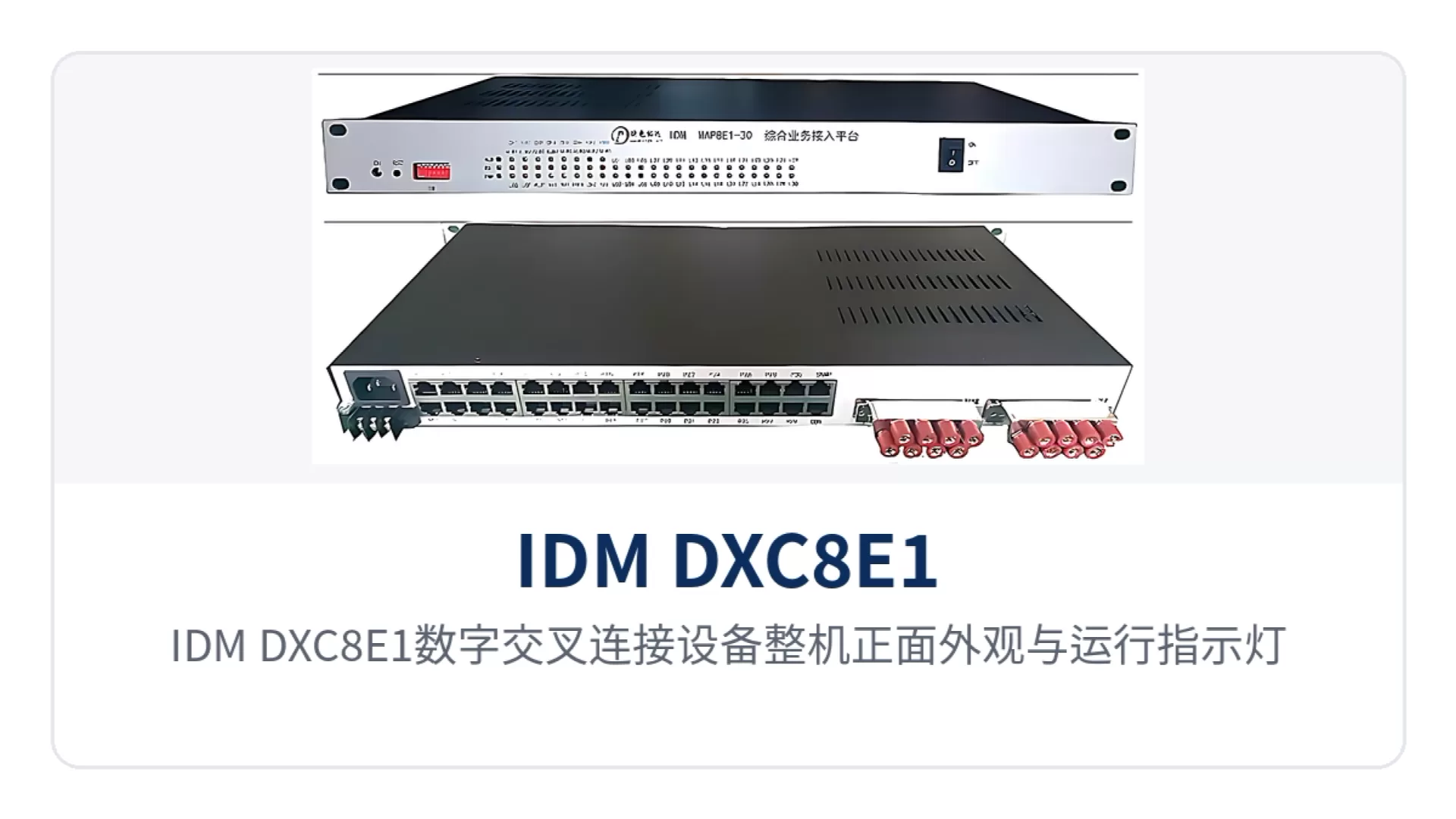
Figure 1: Front view of the IDM DXC8E1 digital cross-connect equipment with operating indicator LEDs
What is an 8-channel E1 digital cross-connect device?
An 8-channel E1 digital cross-connect device is a common cross-connect node at the access layer: on one side it interfaces with transmission equipment or the upper-level network via E1, and on the other side it accesses voice channels and low-speed data through service cards. After services enter the device, they are uniformly split into 64K time slots and then allocated to designated time slots of the target E1 channel according to the circuit plan, without relying on manual patch cords or temporary rewiring.
Moving cross-connect capability down to the access layer is what distinguishes the 8-channel E1 digital cross-connect device from ordinary PCM equipment. Voice channels and data at the site side do not all need to be sent to the central equipment room for queuing and scheduling; time slot allocation can be completed locally, occupying only 1U of cabinet space. When service types change, only the service card needs to be replaced, while the existing E1 lines and peer devices remain unchanged. For sites requiring integrated service access, the device can simultaneously perform PCM multiplexing and 64K service access, serving as an integrated service access device.
The 8 E1 channels can form three types of structures: point-to-point, chain network, and star network, with inter-station services uniformly arranged by E1 channel and time slot number. The device provides complete synchronous timing functions, supplying a unified clock reference for E1 channels and all service interfaces, and reducing the impact of cumulative wander on services in multi-level cascading. As time-slot cross-connect equipment, its cross-connect granularity is 64K, making it suitable for service aggregation and grooming at small-capacity access-layer sites.
What are the core functions?
The functions of the IDM DXC8E1 digital cross-connect equipment revolve around three threads: E1 cross-connection, 64K service access, and centralized maintenance. The table below groups them by link, access, and maintenance; during selection, compare each item against the actual project services, and unused function items need not be configured.
| Function | Description |
|---|---|
| 8-channel E1 cross-connection | All time slots of the 8 E1 channels participate in cross-connection; any input time slot can be scheduled to any output time slot, and connections do not compete for matrix resources |
| 64K time-slot cross-connection | Connections are established one by one in units of 64K time slots, specifying the input E1 channel and time slot and the output E1 channel and time slot according to the service plan |
| 30-channel 64K service access | The main board provides 15 service card slots, each card providing two service channels, and a full configuration provides 30 channels of 64K narrowband services |
| PCM multiplexing | 64K services are multiplexed into 2.048 Mbit/s E1 channels according to the PCM30/32 frame structure, with voice encoded in ITU-T G.711 A-law |
| Voice channel access | Provides three types of voice channel interfaces: FXO central office automatic telephone, FXS remote automatic telephone, and MAG magneto telephone, selected according to site-side equipment |
| Data access | Covers V.24/RS232/RS485/RS422, X.50/X.58, codirectional 64K, n×64K V.35/V.36, and Ethernet bridging |
| Ethernet channel | FE and GE interfaces are accessed via RJ-45, with bandwidth allocated by N×VC12, supporting IEEE802.3 and adaptive half-duplex/full-duplex |
| Synchronous timing | Provides complete synchronous timing functions, supplying a unified clock reference for E1 channels and all subscriber interfaces |
| Network management | Provides serial port network management or Ethernet SNMP network management to view link status, service card configuration, and cross-connection relationships |
| Dual power input | AC 220 V and DC -48 V power input modes are available; at the site, connect one according to the existing power conditions |
After function configuration is complete, cross-connection relationships and service card status can be viewed through serial port network management or Ethernet SNMP network management. When adding sites or adjusting service assignment during operation, only the cross-connect configuration needs to be changed; no on-site rewiring or service card replacement is required. Raytrans uses a unified service card and network management system across this series of PCM equipment, facilitating batch deployment across multiple sites and spare parts commonality.
How is 64K time-slot cross-connection implemented?
Knowledge block: PCM30/32 frame structure and G.703 interface standard. PCM30/32 is the frame structure standard for the E1 base group, with 32 time slots per frame, of which TS0 is used for frame alignment and alarms, TS16 for channel-associated signaling, and the remaining 30 time slots carry 64K services. The E1 interface has a bit rate of 2.048 Mbit/s and HDB3 line coding, complying with the ITU-T G.703 standard, and cross-connect configuration is performed within this frame structure at 64K granularity.
The key to non-blocking cross-connection lies in cross-connect granularity and matrix resources. The IDM DXC8E1 digital cross-connect equipment uses 64K time slots as the cross-connect granularity, establishing an independent connection for each time slot of the 8 E1 channels, so that any input time slot can be connected to any output time slot. The E1 interface impedance can be selected as 75 Ω coaxial or 120 Ω balanced; both forms enter the same cross-connect matrix after access, connections do not compete for resources, and adding a circuit will not push existing circuits out of the matrix.
Cross-connection relationships are delivered as a configuration table. When a site is expanded or services are migrated, only the cross-connect table is adjusted, while the transmission line and peer device remain unchanged; when the routing of a circuit needs to be checked, it can be traced level by level from the configuration table by channel number and time slot number to locate the specific transmit and receive ends, so troubleshooting does not require checking each device one by one. This mechanism allows the time-slot cross-connect equipment to serve as an access-layer node in government private network optical fiber communication solutions, working with SDH/MSTP transmission equipment to complete time-slot-level scheduling of private network voice and data.
Which 64K services can be mixed in the 15 slots?
The main board provides 15 service card slots, each card providing two service channels, and a full configuration provides 30 channels of 64K services. Voice cards and data cards are combined according to the site service list, with cards selected in pairs by service type at the transmit and receive ends, and after mixing they are allocated by the cross-connect matrix to the target E1 time slots.
| Service card type | Interface standard and parameters | Typical access object |
|---|---|---|
| FXS | Audio 300 Hz to 3400 Hz, G.711 A-law, loop current 20 mA/channel | Site office telephones, dispatch telephones, fax machines |
| FXO | Audio 300 Hz to 3400 Hz, G.711 A-law, three-element complex impedance 200 Ω+560 Ω//0.1 μF | Switch subscriber lines, local exchange trunks |
| Magneto | Audio 300 Hz to 3400 Hz, balanced 600 Ω, return loss no less than 18 dB | Magneto telephones, dispatching exchanges, common battery telephones |
| EM 2/4-wire | Audio 300 Hz to 3400 Hz, balanced 600 Ω, G.711 A-law | Audio trunks, PA and amplification equipment |
| V.24/RS232/RS485/RS422 | Asynchronous ≤9600 bps; synchronous 64 Kbps, compliant with CCITT V.28 protocol | Telecontrol terminals, serial data acquisition devices |
| Codirectional 64K | G.703 standard, 64 Kbps, balanced 120 Ω | Protection signals, leased-line data |
| V.35/V.36 | n×64 Kbps (n=0 to 31), RJ-45, terminal interface compliant with ISO2593 | Router WAN ports, synchronous data terminals |
| Ethernet bridge | RJ-45, N×VC12, supporting IEEE802.3 | Remote Ethernet interconnection |
Card configuration follows three steps: first, count the number of telephone, magneto, EM audio, and serial port data channels to determine the card type and quantity of each service card; then check the time slot allocation of the 30 channels of 64K services across the 8 E1 channels, mapping each service to a specific channel and time slot by direction; finally, use serial port network management or Ethernet SNMP network management to verify that the configuration matches the actual services. In military emergency communications vehicle solutions, the 15 slots can be temporarily mixed with voice channel cards and data cards according to on-site tasks, converging voice and data onto the vehicle-mounted transmission channel through PCM multiplexing; in smart mining communication solutions, the same chassis can access underground dispatch telephones, telecontrol data, and Ethernet services, reducing the variety of underground equipment.
How are 30 channels of 64K services allocated to 8 E1 channels?
Each E1 provides 30 64K service time slots according to the PCM30/32 frame structure, and the time slots of the 8 E1 channels all enter the same cross-connect matrix. The 30 channels of 64K services accessed at the site side can occupy any idle time slot and be allocated to any E1 direction; voice and data need not be bound to fixed ports, and planning only requires numbering each circuit in the circuit list.
Time slot planning starts with the number of peers. When all services are sent to the same peer, the 8 E1 channels can be configured for load sharing or some channels can be reserved for active/standby protection; when services are sent to multiple peers, first allocate E1 channels by peer, then designate specific time slots within the channel, avoiding the same time slot being occupied by two circuits. When used as an integrated service access device, the 30 channels of 64K services and the PCM multiplexing channels share the same cross-connect table, keeping the planning approach consistent.
How does AC 220 V/DC -48 V dual power input suit equipment rooms and field sites?
Dual power input means the same model can connect to either AC 220 V or DC -48 V, with one mode connected at the site according to the existing power conditions. Substations and communications equipment rooms generally have both mains and DC power systems, while field sites more often use -48 V battery banks; the same model can cover both types of sites, unifying spare parts and O&M practices.
The overall power consumption is ≤150 W, the operating temperature is -10 ℃ to +50 ℃, the relative humidity is 0 to 95% (non-condensing), and the dimensions are 482×309×44 (mm). The 19-inch 1U chassis can be installed in a standard cabinet or a vehicle-mounted rack; before wiring, check the output voltage and capacity of the power distribution panel, and follow the supplied wiring diagram for AC and DC wiring respectively.
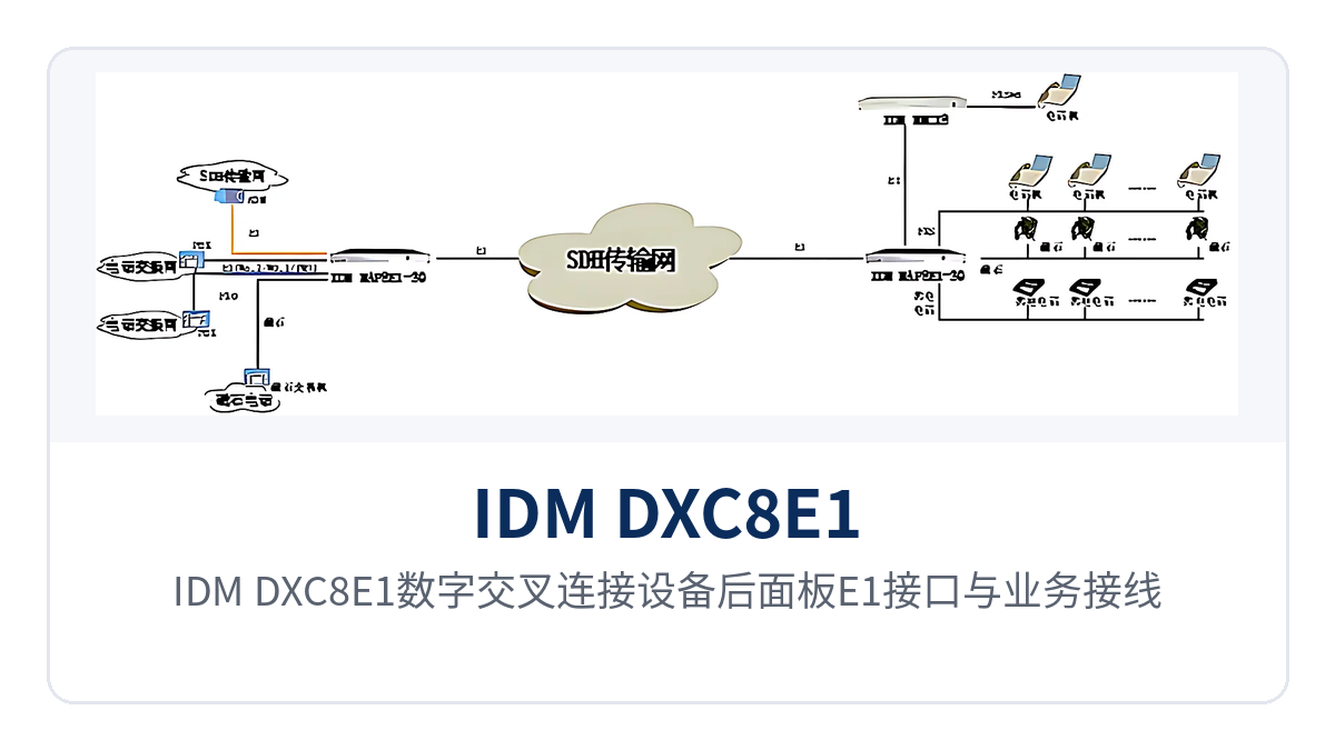
Figure 2: Rear panel layout of the IDM DXC8E1 digital cross-connect equipment showing E1 interfaces and service wiring terminals
Technical Specifications
As a typical PCM multiplexing and integrated service access device, the IDM DXC8E1 digital cross-connect equipment has E1 interfaces compliant with ITU-T G.703 and PCM30/32, audio interfaces using ITU-T G.711 A-law companding, V.24 interfaces compliant with CCITT V.28 protocol, and V.35 interfaces compliant with ITU-T V.35 recommendations. The parameters below are taken from publicly available product technical documentation; specific configurations are subject to the manufacturer's technical documentation and commercial confirmation.
E1 Interface Parameters
| Item | Parameter/Specification | Description/Applicable Conditions |
|---|---|---|
| Number of channels | 8 channels | Non-blocking 64K-level cross-connection among 8 E1 channels |
| Bit rate | 2.048 Mbps | Standard E1 line rate |
| Line coding | HDB3 | Line coding compliant with ITU-T G.703 |
| Standard protocol | Supports ITU-T G.703 | International standard followed by the E1 interface |
| Impedance | 75 Ω/120 Ω | Select 75 Ω coaxial or 120 Ω balanced according to the opposite-end line |
| Frame structure | PCM30/32 | 32 time slots per frame, 30 time slots carrying services |
| Signaling | Channel-associated signaling (CAS) | Line and voice channel status transmitted along with the voice time slot |
Audio Interface Parameters
| Item | Parameter/Specification | Description/Applicable Conditions |
|---|---|---|
| Audio range | 300 Hz to 3400 Hz | Transmission band of the analog audio voice channel |
| Compression | ITU G.711 A-law | Voice companded into a 64 kbit/s voice channel |
| Impedance (FXO/FXS) | Three-element complex impedance 200 Ω + 560 Ω//0.1 μF | Used when interfacing with the audio interface on the switch side |
| Loop current | 20 mA/channel | Working loop current of the audio voice channel |
| Impedance (magneto/EM) | Balanced 600 Ω | Access of magneto telephones and EM 2/4-wire audio trunks |
| Return loss | No less than 18 dB | Specification of the balanced 600 Ω audio interface |
Data and Ethernet Interface Parameters
| Item | Parameter/Specification | Description/Applicable Conditions |
|---|---|---|
| V.24 transmission rate | Asynchronous ≤9600 bps; synchronous 64 kbit/s | Electrical characteristics compliant with CCITT V.28 |
| V.35 transmission rate | n×64 kbit/s (n=0 to 31) | Interface type RJ-45, compliant with ITU-T V.35 recommendation |
| V.35 terminal interface | Compliant with ISO2593 | Interfacing with standard V.35 connectors |
| Codirectional 64K | Line coding per G.703, 64 kbit/s, balanced 120 Ω | Compliant with ITU G.703 recommendation |
| FE interface | RJ-45, N×VC12 (N≤50) | Supports IEEE802.3, full/half duplex/adaptive |
| GE interface | RJ-45, N×VC12 (N≤63) | Supports IEEE802.3, full/half duplex/adaptive |
Power Supply and Environmental Parameters
| Item | Parameter/Specification | Description/Applicable Conditions |
|---|---|---|
| Power supply mode | AC 220 V/DC -48 V | Two power input modes available |
| Overall power consumption | ≤150 W | Upper limit of overall power consumption |
| Operating temperature | -10 ℃ to +50 ℃ | Equipment room and outdoor cabinet environments |
| Relative humidity | 0 to 95% (non-condensing) | Normal operation under non-condensing conditions |
| Dimensions | 482×309×44 (mm) | 19-inch 1U chassis, length × depth × height |
Typical Application Scenarios
As a PCM equipment for private network access, the IDM DXC8E1 digital cross-connect equipment suits private network access nodes that use E1 as the transmission medium and carry a mix of service types within the site. The differences among the three industries lie mainly in the E1 networking structure and the combination of service cards. Most projects adopt a point-to-point or chain network structure, with one PCM equipment at each end connected by an E1 channel and services configured symmetrically at both ends; the interface density and plug-in card flexibility shown in the product are fully reflected in such scenarios.
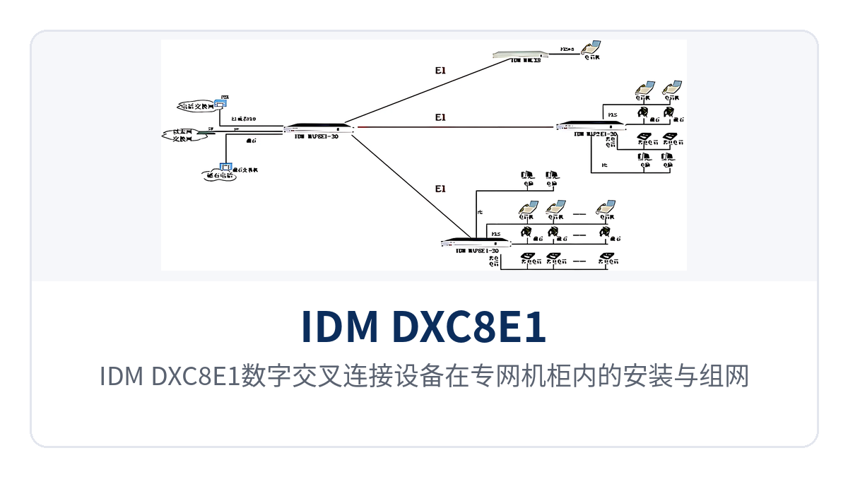
Figure 3: Installation and networking schematic of the IDM DXC8E1 digital cross-connect equipment in a private network cabinet
Electric Power Private Network: Dispatch Telephone and Telecontrol Data Carried by One Unit
Between a substation and the dispatch center there are usually two types of services, dispatch telephone and telecontrol data, with one or two E1 channels provided by transmission equipment. The equipment uses FXS and FXO cards to connect dispatch telephones and switch subscriber lines, and V.24 or RS232 cards to connect telecontrol terminals; the two types of services are multiplexed into the E1 channel and sent to the dispatch center. One unit replaces the previous combination of a telephone optical multiplexer and a data converter, and the PCM multiplexing capability makes in-station service access more economical.
Where the station has both an AC panel and DC power, connect AC 220 V or DC -48 V according to site conditions, keeping spare parts and wiring consistent. When multiple substations are chained to the dispatch center, the time slots of intermediate sites can be dropped and inserted locally as required, and adjustment of the primary channel does not affect the existing voice channels of other sites; the fine-grained cross-connect capability of the time-slot cross-connect equipment comes into play here.
Rail Transit Private Network: Aggregation of Voice Channels and Monitoring Data in Section Equipment Rooms
Section equipment rooms and stations of rail transit are scattered, and the E1 channels reserved at each site are limited, while section telephones, PA audio and monitoring data need to be accessed within the site. These services are implemented on service cards inserted into the same 1U chassis, presenting only E1 line interfaces externally, so cabinet space and supporting power supply are reduced accordingly; the integration advantage of the integrated service access device is evident.
Section telephones are sent to the central dispatch center and monitoring data to the integrated monitoring system; since the two opposite ends differ, E1 channels are allocated by opposite end and designated time slots are then assigned within the channels. When new services are added, cards are added in free slots, while the existing E1 channels and cabling remain unchanged, so the upgrade does not require shutting down existing voice channels.
Military and Government Private Network: Cross-Connect Multiplexing Between Command Posts and Forward Sites
Sites of military and government private networks have many interface types and non-uniform line sources, including E1 channels provided by existing optical transmission equipment and temporarily set up circuits. The equipment mixes and inserts telephones, magneto, EM audio and serial port data, and then distributes them to target E1 time slots through the 64K cross-connect matrix. It suits service interfacing between command posts and forward sites and supports rapid implementation of military emergency communications vehicle solutions and government private network optical fiber communication solutions.
When a communication vehicle and a fixed station building set up a channel, one equipment is placed at each end, and dual power supply allows the vehicle-mounted DC power and the station building AC power to use the same model. The E1 link can be configured as active/standby, so when one path is interrupted services are carried by the other, with link backup and service access completed within the same unit. Raytrans series PCM equipment can also be used in similar private network projects for service aggregation and access in scenarios such as smart mining communication solutions.
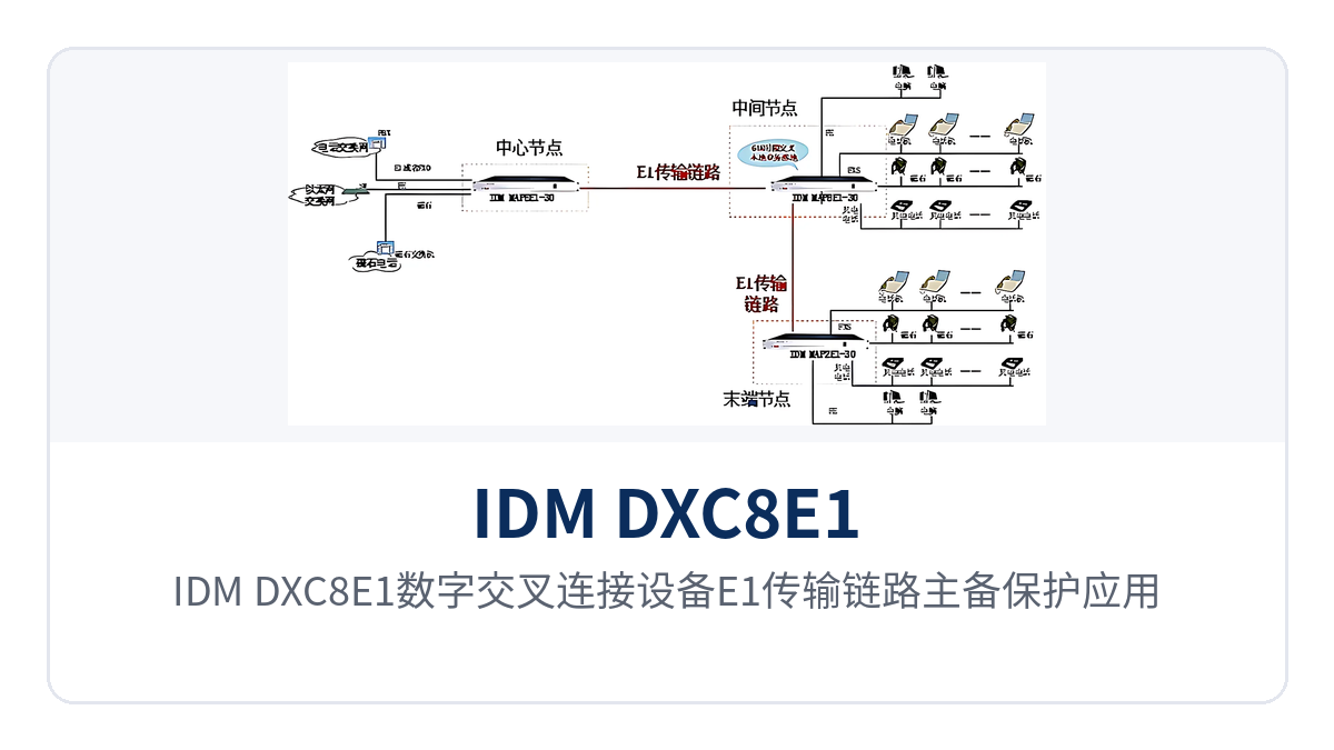
Figure 4: Application schematic of active/standby protection for the E1 transmission link of the IDM DXC8E1 digital cross-connect equipment
How to Select an 8-Channel E1 Digital Cross-Connect Equipment?
For selection, first determine the capacity according to the site service list, then determine the E1 configuration and interface card types according to line conditions. The following five items are the checkpoints; once confirmed one by one, they can be translated into the configuration list and quotation basis. On site, cabinet space, power supply format and existing cabling labels should also be checked to avoid a mismatch between the configuration list and installation conditions.
- Service types and number of channels: count the channels of telephone, magneto, common battery telephone, EM audio, serial port data and Ethernet interconnection, and determine the types and quantities of service cards accordingly.
- E1 channels and networking: confirm the number of opposite-end devices and the network structure; point-to-point, chain network and star network structures have different time slot planning methods, and active/standby channels must be reserved separately.
- Interface specifications and impedance: select 75 Ω coaxial or 120 Ω balanced E1 impedance according to the opposite end; select FXS, FXO or magneto cards for voice channels according to the opposite-end device, and V.24, V.35 or codirectional 64K cards for data according to the interface type.
- Power supply and environment: connect AC 220 V in AC equipment rooms and DC -48 V at DC power supply sites; for outdoor cabinets, check the operating temperature and humidity ranges as well.
- Network management and capacity expansion: confirm whether serial port network management or Ethernet SNMP network management is used, and reserve card slots and E1 time slot margin for subsequent service growth.
At the selection stage, cross-connect granularity and the capacity expansion approach should also be checked: cross-connections are configured time slot by time slot at 64K, and capacity expansion only requires changing the cross-connect table and adding service cards, while the unit and existing lines remain unchanged. Investment in access nodes can be made step by step as services grow, and subsequent expansion does not require laying inter-station lines again.
Conclusion
As an 8-channel E1 digital cross-connect equipment, the IDM DXC8E1 packs non-blocking E1 cross-connection, 30-channel 64K service access and PCM multiplexing into a compact 1U chassis. AC 220 V/DC -48 V dual power input suits private network equipment rooms and field sites, and V.24, V.35, E1 and audio multi-service access is provided by one unit, so access nodes no longer need to cascade multiple single-function devices. Raytrans can confirm PCM equipment configuration and networking structure based on the typical requirements of government private network optical fiber communication solutions, military emergency communications vehicle solutions and smart mining communication solutions.
Beijing Ruiguang Jiyuan Digital Technology Co., Ltd. can confirm service card configuration, time slot planning and networking structure based on site topology and service lists, and provide selection and commissioning support, facilitating step-by-step implementation of access layer upgrades for electric power, rail transit, and military and government private networks.