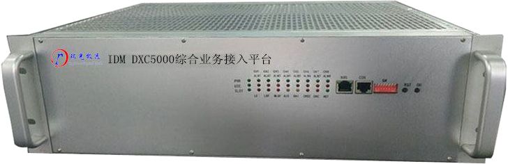
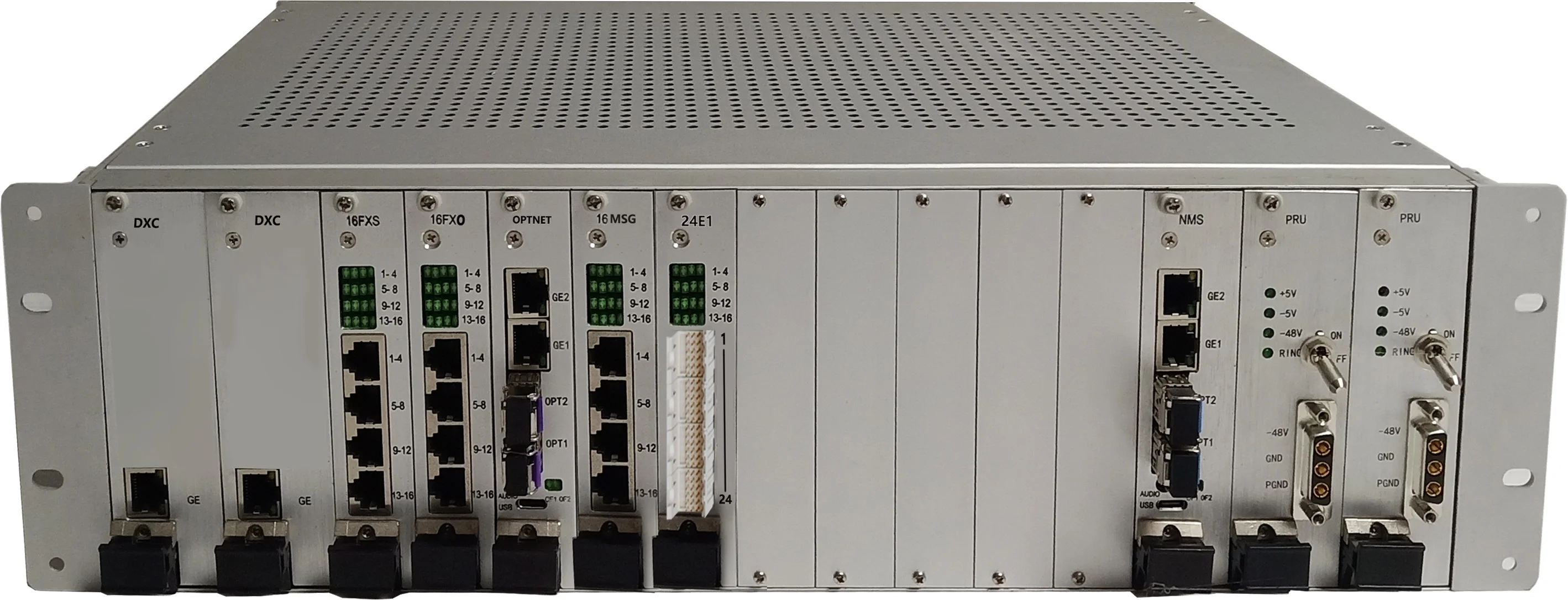
IDM DXC5200 时隙交叉设备
IDM DXC5200时隙交叉设备满配240组标准的E1传输接口。同时具有240组E1之间64K时隙无阻塞交叉连接设备。同时该设备具有多种时钟模式,能够满足各种应用环境的时钟需求。 该设备主控盘、电源盘等关键模块采用双盘互备份。
Gallery
title: "IDM DXC5200 Timeslot Cross-Connect Equipment"
model: "IDM DXC5200"
category: "PCM"
tags:
- "DXC Equipment"
- "DXC Cross-Connect Equipment"
- "DXC Timeslot Cross-Connect Equipment"
- "DXC Non-blocking Cross-Connect Equipment"
- "PCM Equipment"
- "E1 Cross-Connect Equipment"
- "E1 Timeslot Cross-Connect Equipment"
- "DXC Digital Cross-Connect Equipment"
- "Dual Main Control Redundant DXC"
description: "The IDM DXC5200 timeslot cross-connect equipment is fully configured with 240 standard E1 transmission interfaces. It also features non-blocking 64K timeslot cross-connect capability among the 240 E1 interfaces. The equipment supports multiple clock modes to meet the clock requirements of various application environments. Key modules such as the main control board and power supply board adopt dual-board mutual redundancy."
cover: "/images/imports/img-967e7c94.webp"
images: - "/images/imports/img-967e7c94.webp"
- "/images/imports/img-93e3a4c7.webp"
keywords: "DXC equipment,DXC cross-connect equipment,DXC timeslot cross-connect equipment,DXC non-blocking cross-connect equipment,PCM equipment,E1 cross-connect equipment,E1 timeslot cross-connect equipment,DXC digital cross-connect equipment,dual main control redundant DXC"
slug: "idm-dxc5200"
publishDate: "2026-05-12"
I. Overview
The IDM DXC5200 timeslot cross-connect equipment is one of the timeslot cross-connect devices designed by our company using dedicated large-scale integrated circuits. It completes the connection between user terminal equipment or between user terminal equipment and the public switched telephone network (PSTN) through 2M transmission media.
The IDM DXC5200 timeslot cross-connect is fully configured with 240 standard E1 transmission interfaces, adopting the PCM30/31 format. It also features non-blocking 64K timeslot cross-connect capability among the 240 E1 interfaces. Additionally, the DXC5200 timeslot cross-connect supports multiple clock modes to meet the clock requirements of various application environments.
The IDM DXC5200 timeslot cross-connect adopts dual-board mutual redundancy for key modules such as the main control board and power supply board.
IDM DXC5200 Timeslot Cross-Connect Equipment Image
II. Product Features
u 19-inch 3U standard chassis, with 2 power supply board slots, 2 main control board slots, and 11 service board slots;
u Dual -48V power supply, supporting 1+1 redundancy protection;
u Dual main control, supporting 1+1 redundancy protection;
u Main control board: Supports a cross-connect capacity of 7200×7200 64K timeslots for full cross-connection, providing user interface access and management, data and signaling cross-connection, system synchronization, and device networking control and management; supports digital level adjustment for all E1 channels within a single-end device. The main control board supports remote online upgrade functionality;
u E1 service board: A single board provides 24 E1 interfaces, connected via European-style sockets, supporting remote online upgrade functionality;
u Network management board: Supports online collection of third-party vendor TS16 signaling formats through the network management software, with automatic storage. It can configure signaling formats for any 64K timeslot among the 240 E1 interfaces, enabling interoperability of telephone services with PCM equipment from any manufacturer;
u Test board: Equipped with test ports configured as FXS interfaces. Through the network management system, the test ports can be used to perform tests on designated 64K timeslots, including sending ringing current, sending audio, receiving audio, three-party calling, two-way calling, monitoring, and 64K timeslot bidirectional loopback tests.
u The equipment also supports the insertion of 64K and N*64K service boards. The service types and quantities can be arbitrarily configured within the chassis. Each slot can provide 8 or 10 channels of 64K services, supporting FXS/FXO, magneto, 2/4-wire E&M, RS232/RS422/RS485, and GSM/CDMA services.
III. Technical Specifications
E1 Interface
Bit Rate | 2.048Mbps | Line Code | HDB3 |
Standard Protocol | Supports ITU-T G.703 | Impedance | 75Ω/120Ω |
Frame Structure | PCM30/32 | Signaling | Channel Associated Signaling |
FXO, FXS Interface
Audio Range | 300Hz~3400Hz | Compression | A-law per ITU G.711 |
Impedance | Triple complex impedance 200Ω+560Ω//0.1μF | Loop Current | 20mA/channel |
EM2/4 Line Interface
Audio Range | 300Hz~3400Hz | Impedance | Balanced 600Ω |
Compression | A-law per ITU G.711 | Return Loss | ≥18dB |
V.24 Interface
Transmission Rate | Asynchronous ≤9600bps; Synchronous 64Kbps | Electrical Characteristics | Compliant with CCITT V.28 Recommendation |
V.35 Interface
Interface Type | RJ-45 | Electrical Characteristics | Compliant with ITU-T V.35 Recommendation |
Transmission Rate | n×64Kbps (n=0~31) | Terminal Interface | Compliant with ISO2593 Specification |
Power Supply and Power Consumption
Power Supply | DC/AC | Total Power Consumption | ≤150W |
Environmental Conditions
Operating Temperature | -20oC ~+50oC | Relative Humidity | 0~95% (non-condensing) |
IV. Application Example
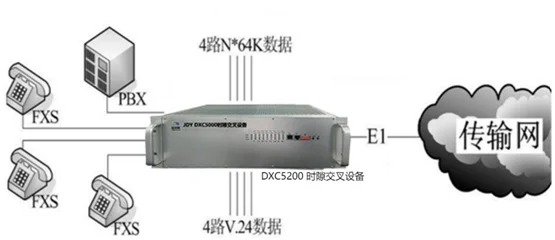
IDM DXC5200 Service Access Diagram