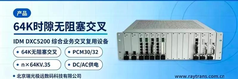
IDM DXC5000 Time-Slot Cross-Connect Equipment
Dual 48V hot standby, dual main control mutual backup, 8 E1 ports expandable to 240 voice channels, 50 VC
The IDM DXC5000 time-slot cross-connect equipment is used in the product showcase field, targeting industry customers' communication/transmission/dispatch equipment (to be further detailed based on documentation)
IDM DXC5000 dual-48V hot-standby time-slot cross-connect equipment is a PCM time-slot cross-connection device designed by Beijing Ruiguang Jiyuan Digital Technology Co., Ltd. using dedicated large-scale integrated circuits. As a professional PCM equipment, it is used on 2M (E1) transmission media to complete, by 64K time slots, the connection and scheduling between subscriber terminals and between subscriber terminals and the public switched telephone network (PSTN). The device adopts dual 48V power supplies with 1+1 hot standby and mutual backup of dual main control units. The main control card provides 8 E1 interfaces, can expand to 240 voice interfaces through 8 E1 links, and supports 50-channel VC12 cross-connection scheduling. Voice, audio, data, and Ethernet services can be accessed in a mixed manner within the same device, making it suitable for scenarios such as electric power and energy private networks, rail transit and expressway communications, and military, government, and emergency command private networks. As a core PCM time-slot cross-connection device under Raytrans, the IDM DXC5000 performs outstandingly in the field of integrated service access devices and can flexibly carry the multi-service access requirements in government private network optical fiber communication solutions and military emergency communications vehicle solutions. Its dual-48V hot-standby design ensures stable operation under the harsh conditions required by command and dispatch system manufacturers, providing reliable PCM product showcase and communications assurance for various command and dispatch systems.
Key Specifications at a Glance: Dual 48V power supplies with 1+1 hot standby · Mutual backup of dual main control cards · 8 E1 interfaces on the main control card · 8 E1 links expand to 240 voice channels · 50-channel VC12 cross-connection · 64K time slot granularity · 19-inch 3U chassis
What Kind of Equipment Is the Dual-48V Hot-Standby Time-Slot Cross-Connect Equipment
The IDM DXC5000 dual-48V hot-standby time-slot cross-connect equipment concentrates three types of capabilities—E1 base group multiplexing, time-slot cross-connection scheduling, and service access—in one PCM equipment, and completes the connection between subscriber terminals and between subscriber terminals and the public switched telephone network over 2M transmission media. Voice, audio, asynchronous data, V.35 data, and Ethernet services can be accessed in a mixed manner on the same E1 transmission channel. On the access side, single-service PCM equipment is no longer stacked separately by service type, and cabinet space usage and the number of cables are reduced accordingly. As an integrated service access device, it is often used in product showcase for government private network optical fiber communication solutions and military emergency communications vehicle solutions.

The device is a 19-inch 3U standard chassis, with 2 power card slots, 2 main control card slots, and 12 service slots in the chassis. The service types and quantities can be configured arbitrarily within the chassis. The front panel is equipped with service interface units and operating indicator LEDs, based on which O&M personnel can determine on the spot the operating status of the unit and each service channel.

The rear panel concentrates the E1 interfaces, service interfaces, and dual 48V power connectors. The E1 interfaces provide two impedance forms, 75Ω/120Ω, in accordance with the ITU-T G.703 standard, and can interface with SDH/PDH transmission equipment and SPC switching equipment; the two 48V power feeds are connected separately, corresponding to the 2 power card slots in the chassis. The slot layout and interface configuration vary with the project configuration. Before purchase, please refer to the manufacturer's technical documentation and commercial confirmation.
Core Functions and Interface Capabilities
The functions of the IDM DXC5000 dual-48V hot-standby time-slot cross-connect equipment cover four categories: time-slot cross-connection, service multiplexing, multi-interface access, and redundant backup. The specific role of each function is shown in the table below.
| Function | Description |
|---|---|
| E1 time-slot cross-connection | Completes cross-connection on 2M transmission media with 64K time slots as the granularity. Voice, data, and Ethernet services can be scheduled as required to designated time slots of designated E1 channels. |
| Mutual backup of dual main control units | The 2 main control card slots back each other up in a 1+1 manner, and key units adopt dual-board mutual backup. When a single main control unit is abnormal, the time-slot cross-connection configuration and service operation are not changed. |
| Dual-48V power supply hot standby | The chassis is configured with 2 power card slots, and the dual 48V power supplies support 1+1 hot standby. The two power feeds are connected separately, and when either feed loses power, the other automatically continues supplying. |
| 8 E1 interfaces on the main control card | The main control card provides 8 E1 interfaces and supports mutual backup of dual main control units, undertaking the access and management of subscriber interfaces, cross-connection of data and signaling, system synchronization, and device networking control and management. |
| 8 E1 links expand to 240 voice channels | Through the 8 E1 links of the main control card, 64K voice time slots are transmitted. All 30 service time slots of each E1 are used for voice access, and the 8 E1 links together expand to 240 voice interfaces. |
| Integrated service multiplexing | Voice, audio, asynchronous data, V.35 data, and Ethernet services are accessed in a mixed manner on the same device, multiplexing the same E1 transmission channel. One device replaces multiple single-service devices. |
| Voice PCM access | Analog voice is compressed to 64Kbps according to ITU-T G.711 A-law and then occupies one 64K time slot. The audio range is 300Hz~3400Hz, and the loop current is 20mA per channel. |
| E1 base group multiplexing and PCM base group multiplexing | Multiplexes multiple 64K service time slots into a 2.048Mbps E1 base group, using the PCM30/32 frame structure and HDB3 line coding, and can interface with existing PCM networks using the same frame structure. |
| Mixed insertion of multi-service interfaces | Supports mixed insertion of FXS/FXO, magneto, 2/4-wire EM, RS232/RS422/RS485, and GSM/CDMA service boards. Each slot can provide 8 or 10 channels of 64K services. |
| Ethernet service transmission | Provides Ethernet services compliant with IEEE802.3. The operating mode supports full/half duplex/adaptive, and the transmission rate is N×VC12 (N≤50). |
Technical Specifications and Operating Conditions
The electrical specifications, power supply conditions, and operating environment of each interface are shown in the table below. They can serve as a basis for networking design and equipment selection, and the specifications in the table are based on the manufacturer's technical documentation.
| Item | Parameter/Specification | Description/Applicable Conditions |
|---|---|---|
| E1 bit rate | 2.048Mbps | Standard E1 base group rate |
| E1 line coding | HDB3 | Complies with the ITU-T G.703 standard |
| E1 standard protocol | ITU-T G.703 | E1 interface electrical specifications |
| E1 impedance | 75Ω/120Ω | Select 75Ω coaxial or 120Ω balanced wiring according to the opposite end |
| E1 frame structure | PCM30/32 | 32 time slots per frame, of which 30 carry services |
| E1 signaling | Channel-associated signaling | Voice channel status is transmitted synchronously with voice time slots |
| Number of E1 interfaces on the main control card | 8 | Supports mutual backup of dual main control units |
| Telephone FXO, FXS audio range | 300Hz~3400Hz | Analog voice channel frequency band |
| Telephone compression ratio | ITU G.711 A-law | Voice is encoded at 64Kbps, occupying one 64K time slot |
| Telephone impedance | Three-element complex impedance 200Ω+560Ω//0.1μF | Analog exchange side audio connection |
| Telephone loop current | 20mA per channel | Loop current required for analog telephone access |
| EM 2/4-wire audio range | 300Hz~3400Hz | Balanced audio dedicated line frequency band |
| EM 2/4-wire impedance | Balanced 600Ω | Balanced audio line access |
| EM 2/4-wire compression ratio | ITU G.711 A-law | Uses the same compression standard as voice |
| EM 2/4-wire return loss | Not less than 18dB | Balanced 600Ω interface specification |
| V.24 transmission rate | Asynchronous ≤9600bps; synchronous 64Kbps | Electrical characteristics comply with the CCITT V.28 protocol |
| V.35 interface type | RJ-45 | Electrical characteristics comply with ITU-T V.35 recommendations |
| V.35 transmission rate | n×64Kbps (n=0~31) | Occupies 1~31 64K time slots as required by services |
| V.35 terminal interface | Complies with ISO2593 | Interfaces with standard V.35 connectors |
| Ethernet transmission rate | N×VC12 (N≤50) | Configure the N value according to service bandwidth requirements |
| Ethernet standard protocol | IEEE802.3 | Standard Ethernet frame format |
| Ethernet operating mode | Full/half duplex/adaptive | Interfaces with the opposite end Ethernet device |
| Power supply mode | Dual 48V power supplies, 1+1 hot standby | Two 48V power cards are connected to two power feeds separately; when either feed loses power, supply continues automatically |
| Chassis and slots | 19-inch 3U chassis; 2 power card slots, 2 main control card slots, 12 service slots | Service types and quantities can be configured arbitrarily within the chassis |
| Overall power consumption | ≤120W | Upper limit of overall power consumption |
| Operating temperature | -20℃~+50℃ | Suitable for both equipment room and outdoor cabinet environments |
| Relative humidity | 0~95% (non-condensing) | Normal operation under non-condensing conditions |
How a Single Main Control Card Expands to 240 Voice Channels with 8 E1 Links
The calculation of the 240 voice channel capacity comes from the product of 8 E1 links and 30 service time slots: the rate of one E1 is 2.048Mbps. When the PCM30/32 frame structure is used, 30 of the 32 time slots in each frame carry services, and a single service time slot is 64Kbps, exactly carrying one channel of 64Kbps encoded voice. The main control card provides 8 E1 interfaces, and 8×30=240. Therefore, through the 8 E1 links of the main control card, the number of voice interfaces can be expanded to 240. This capacity expansion approach based on PCM time-slot multiplexing is a typical application of PCM equipment in integrated service access scenarios.
The capacity expansion approach is to add service cards within the chassis rather than replace the entire unit. Each slot of the device can provide 8 or 10 channels of 64K services, and service cards such as voice, magneto, FXS/FXO, 2/4-wire EM, RS232/RS422/RS485, and GSM/CDMA can be configured arbitrarily in the 12 service slots. The required number of channels is added card by card according to the slots. Service types and quantities are adjusted within the chassis, and service planning on the access side can be implemented in stages: configure according to actual service volume at an early stage, and expand cards as required later.
It should be noted that 240 voice channels correspond to the upper limit of voice interface expansion, and the actual number of accessible channels depends on the number of service cards already configured in the chassis and the number of channels per card. During planning, first calculate the number of service cards according to the number of telephone channels required by the site, then check whether the uplink E1 channel meets the time slot occupation. After the two match, determine the final configuration.
How 50-Channel VC12 Cross-Connection Scheduling Allocates Multi-Service Bandwidth
50-channel VC12 cross-connection scheduling is the key to flexible allocation of private network bandwidth: one VC12 container corresponds to one 2.048Mbps E1 channel, and the device supports channel organization of N×VC12 (N≤50), that is, a 50-channel VC12 cross-connect capacity, with the N value configured according to service bandwidth requirements. When services are expanded or the structure is adjusted, modifying the time-slot cross-connection configuration reallocates the time slot positions occupied by each service, without changing the transmission line. As a PCM time-slot cross-connection device, its cross-connection scheduling capability directly determines the bandwidth utilization efficiency of the integrated service access device in multi-service scenarios.
Various services occupy different bandwidth granularities on the access side. Telephone and audio services each occupy an independent 64K time slot; the V.35 data interface occupies multiple time slots in n×64Kbps (n=0~31) to carry synchronous data; the asynchronous data interface carries low-speed data at synchronous 64Kbps or asynchronous ≤9600bps; Ethernet services are configured with bandwidth according to N×VC12. After multiple services multiplex the same E1 transmission resource, they are uniformly sent to the transmission network, and the bandwidth occupation of the access unit can be adjusted separately according to service volume.

The value of time-slot cross-connection lies in the fact that service paths can be reorganized as required. The 30 64K time slots within one E1 can either all carry voice or be allocated as required to data and audio, and the cross-connection relationships are determined by network management configuration. Within the same site, E1 channels in different directions can also be cross-connected, and telephone services across directions and sections no longer need to rely on additional wiring jumpers for intercommunication.
How Dual 48V Hot Standby and Dual Main Control Mutual Backup Ensure Services Uninterrupted
Dual 48V hot standby and dual main control mutual backup provide redundancy for two types of single points of failure: power supply and main control. The dual 48V power supply supports 1+1 hot standby, with two power cards connected to two power feeds respectively; when either feed loses power, the other automatically continues supplying power. Dual main control mutual backup means that 2 main control cards back each other up in a 1+1 manner, so that when a single main control unit is abnormal, services and time-slot cross-connection configuration are not affected. With these two capabilities combined, the key circuits of private network dispatch remain uninterrupted.
In electric power, rail transit, and military and government private networks, service channels often span multiple sections of transmission equipment, and a power supply interruption or main control unit failure at the site side may affect dispatch telephone and data services. The 2 power card slots and 2 main control card slots in the chassis provide the physical basis for the two types of redundancy. After key units adopt dual-board mutual backup, the unit no longer depends on a single board for operation, and O&M personnel can replace a faulty board while services are running.

The switchover mechanism, switchover time, and associated alarm methods for power supply and main control are subject to the manufacturer's technical documentation. Before deployment, it is recommended to confirm the redundancy configuration solution with Beijing Ruiguang Jiyuan Digital Technology Co., Ltd. based on the on-site transmission network and power supply conditions, and to complete a comprehensive drill of power supply switchover and main control switchover before formally putting services into operation.
Typical Application Scenarios
Electric Power and Energy Private Network: Dispatch Telephone and Data Access for Substations and Dispatch Centers
In electric power and energy private networks, dispatch telephone, audio services, and telecontrol data between substations, power plants, and dispatch centers are usually transmitted along E1 channels. The IDM DXC5000 dual 48V hot standby time-slot cross-connect equipment is deployed at the site side, accessing analog telephone, audio services, and asynchronous data and multiplexing them onto the E1 base group, then distributing each service time slot to the uplink channel through E1 time-slot cross-connection to interface with dispatching switching equipment. When the site uses 48V DC power supply, it can be directly connected to dual power supply from the station power system. The design goal is that dispatch telephone and data services remain uninterrupted when a single power feed or a single main control card is abnormal.
Rail Transit and Expressway Communications: Voice and Data Aggregation for Stations, Toll Stations, and Sections
In rail transit and expressway along-the-line communication systems, E1 channels are often used between stations, toll stations, tunnel portals, service areas, and section management centers to carry dedicated telephone, public address audio, and transmission data. The IDM DXC5000 dual 48V hot standby time-slot cross-connect equipment can serve as an access and cross-connect node at the station or toll station side, multiplexing in-station telephone and audio services onto the uplink E1 channel in 64K time slots, and completing time-slot cross-connection transfer at section nodes, so that telephone services in different sections can intercommunicate as required. The V.35 data interface and asynchronous data interface can access data from along-the-line transmission equipment and monitoring equipment, enabling voice and data to be carried within the same transmission channel.
Military, Government, and Emergency Command Private Networks: Multi-Service Access for Field Sites and Temporary Command Posts
In military, government, and emergency command private networks, there are a large number of field sites, temporary command posts, and unattended cabinets, where power supply and duty conditions are relatively demanding. The IDM DXC5000 dual 48V hot standby time-slot cross-connect equipment adopts dual 48V power supply 1+1 hot standby, can be directly powered by the site DC power system, has overall power consumption ≤120W, an operating temperature of -20℃+50℃, and a relative humidity of 095% (non-condensing). Telephone, audio, data, and Ethernet services are accessed and then backhauled to upper-level nodes via E1 channels. One device handles the access and scheduling of multiple types of services, and the number of devices and cables within the site is reduced accordingly. For military emergency communications vehicle solutions and government private network optical fiber communication solutions, such PCM equipment with dual 48V hot standby capability can complete multi-service product showcase-level integrated access within limited space, and is also an integrated service access device that command and dispatch system manufacturers focus on when selecting solutions.
Power Supply and Environmental Adaptability: Dual 48V Hot Standby, Power Consumption ≤120W, Wide Temperature -20~50℃
The power supply mode of the IDM DXC5000 dual 48V hot standby time-slot cross-connect equipment is dual 48V power supply 1+1 hot standby, with two power cards connected to two power feeds respectively; when either feed loses power, the other automatically continues supplying power. The overall power consumption is ≤120W, the operating temperature is -20℃+50℃, and the relative humidity is 095% (non-condensing). These specifications determine that the equipment can be deployed both in a central equipment room and in cabinets, base stations, and unattended sites that use 48V DC power supply, and serve as the basis for selection in electric power and energy and field site scenarios.
During selection, it is necessary to check whether the two 48V power feeds have independent sources according to the site power supply capability, so as to avoid both feeds being taken from the same power supply and losing the meaning of backup. Equipment room and cabinet deployment should ensure ventilation and heat dissipation conditions. Long-term unattended sites are recommended to be used with alarm and remote management means, and in combination with dual main control mutual backup capability, to reduce the number of manual site visits.
Selection and Deployment Recommendations
When selecting the IDM DXC5000 dual 48V hot standby time-slot cross-connect equipment, first count the number of E1s requiring cross-connection scheduling, as well as the number of channels for telephone, audio, asynchronous data, V.35 data, and Ethernet services, and accordingly plan the 64K time slot occupation and the N×VC12 (N≤50) bandwidth configuration. Then confirm according to site conditions whether two independent 48V power feeds can be provided, and whether the ambient temperature falls within the -20℃~+50℃ range. Finally, determine the 75Ω or 120Ω impedance configuration and the service card configuration quantity according to the opposite end line form.
The equipment adopts the PCM30/32 frame structure and channel-associated signaling, and can interconnect with existing PCM networks using the same frame structure. Capacity expansion or service adjustment only requires modifying the cross-connect configuration. Deployment is recommended to proceed in three steps: first complete cabinet installation and dual power supply access and check the indicator LED status of the power cards and main control cards; then complete the access of E1 channels and service cards, and check the time-slot cross-connection configuration one by one; finally carry out service commissioning and redundancy switchover drills, and put it into formal operation after confirming that telephone, data, and Ethernet services are normal.
Conclusion
The IDM DXC5000 dual 48V hot standby time-slot cross-connect equipment is based on dual 48V power supply 1+1 hot standby and dual main control mutual backup. The 8 E1 interfaces of the main control card can expand the number of voice interfaces to 240 through 8-channel E1 expansion, and 50-channel VC12 cross-connection scheduling organizes telephone, audio, asynchronous data, V.35 data, and Ethernet services within the same transmission channel, with one integrated service access device replacing multiple single-service PCM equipment. The 19-inch 3U chassis, overall power consumption ≤120W, and operating temperature range of -20℃~+50℃ make it suitable not only for central equipment rooms but also for site deployment in electric power and energy private networks, rail transit and expressway communications, government private network optical fiber communication solutions, and military emergency communications vehicle solutions. To confirm interface configuration, time-slot cross-connection solutions, and pricing information, please contact Raytrans (Beijing Ruiguang Jiyuan Digital Technology Co., Ltd.), as a professional command and dispatch system manufacturer, to provide you with support.
FAQs
What is the working principle of Pulse Code Modulation (PCM)?
Working Principle Pulse Code Modulation is the process of converting a time-continuous…
View answerPCM30 Working Principle: What Is PCM30/32
PCM30 Equipment Working Principle The 30-channel PCM equipment refers to equipment that provides 30 user interfaces and…
View answerWhat are the common problems of PCM equipment in enterprise applications?
At present, PCM equipment has become basically ubiquitous in enterprise network applications.
View answerWhat is E1? How to Use E1
What is E1 The European 30-channel pulse code modulation PCM is abbreviated as E1, with a rate of 2.048Mbit/s.
View answerFrame Structure of 30/32-Channel PCM Primary Group
A communication system consists of transmitting equipment, receiving equipment, and transmission equipment.
View answer