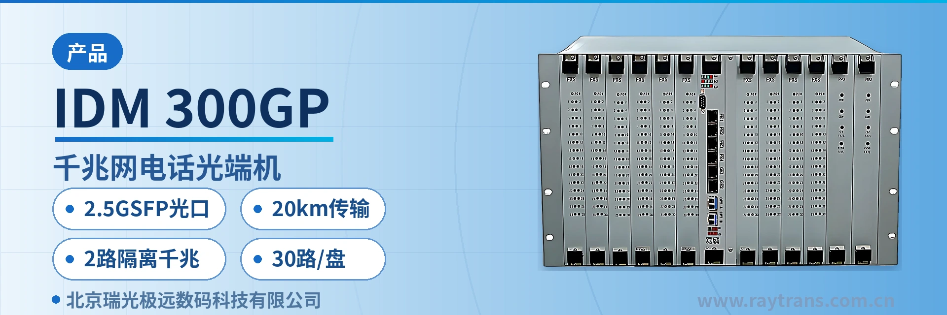
IDM 300GP Gigabit Network Telephone Optical Multiplexer
14 card slots, on-demand card insertion, 30 channels per card, 300 channels in full configuration, 2 isolated gigabit interfaces, 8 groups
The IDM-300GP gigabit network telephone optical multiplexer provides 2 physically isolated line-rate 1000M Ethernet interfaces and 8 E1 transparent transmission interfaces. The device features a card-based structure, with each service card providing 30 telephone channels. It is simple to install and easy to maintain.
IDM 300GP telephone optical multiplexer is a card-based 2.5G telephone optical multiplexer developed by Beijing Ruiguang Jiyuan Digital Technology Co., Ltd. It multiplexes 2 physically isolated wire-speed 1000M Ethernet interfaces, 8 groups of E1 transparent transmission interfaces, and FXO/FXS voice channels with caller ID (CID) onto a single 2.5Gbps optical fiber channel for transmission. Voice, E1 trunk, and broadband data each occupy an independent channel on the same optical path, and a single device at the site side can complete centralized backhaul. It is a typical product showcase of multi-service access in a government private network optical fiber communication solution.
The card-based structure with capacity growing by card slot is the organizational approach that distinguishes this card-based 2.5G telephone optical multiplexer from fixed-port devices. The chassis provides 14 card slots; a single service card carries 30 telephone channels, and 10 service cards in full configuration reach the full capacity of 300 telephone channels, with 2 main control card slots and 2 power card slots configured as standard. During commissioning, cards are inserted according to site traffic; capacity expansion only adds service cards without changing the chassis or backplane. As a professional optical multiplexer manufacturer, Raytrans also offers product forms such as gigabit network optical multiplexer, multi-service optical multiplexer, and PDH optical multiplexer in this series, facilitating selection as needed during networking.
Key Specifications at a Glance: 2.5G SFP optical port · 20 km transmission · 2 isolated gigabit interfaces · 8 groups of E1 transparent transmission · 30 channels/card, 300 telephone channels in full configuration · 14 hot-swappable card slots · AC220V/DC-48V · overall power consumption ≤90 W
What kind of equipment is the card-based 2.5G telephone optical multiplexer
IDM 300GP telephone optical multiplexer is a telephone access and optical fiber transmission device with a centralized card-based chassis structure, and the 14 card slots in the chassis have clear divisions of labor. The 10 service card slots carry telephone services, the 2 main control card slots handle access management of the chassis and service cards, and the 2 power card slots provide 1+1 mutual backup power supply, so that when one power card fails, the other continues to supply power to the chassis. As a product showcase model launched by the professional optical multiplexer manufacturer Raytrans, this device is a high-density centralized representative among telephone access optical multiplexers.
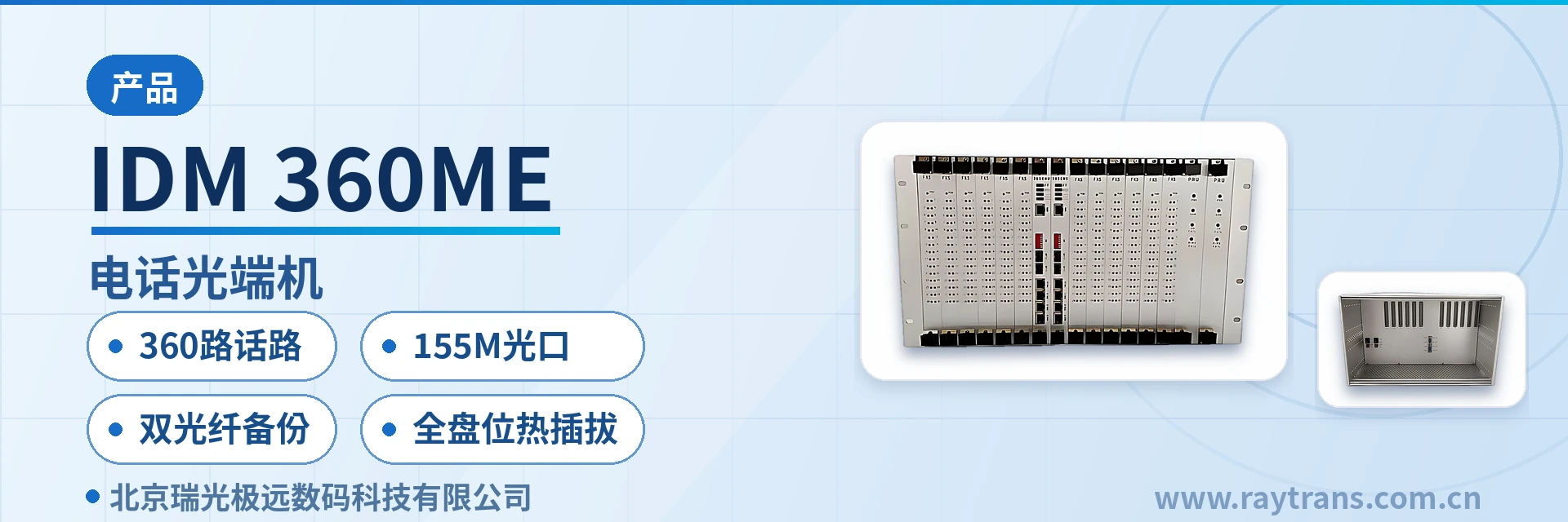
The unit is a 19-inch standard 6U chassis with dimensions of 482×266×270 mm (Length×Depth×Height), compliant with telecom and carrier standards, and occupies 6U of installation space in a standard cabinet. All card slots support hot-swappable operation; during commissioning, cards are inserted one by one according to the service list, and during O&M, the faulty card slot is located by alarm and replaced online without powering down the entire unit. Installation actions are positioned by card, and capacity expansion actions are inserted by card, so that on-site work and later maintenance are both carried out in units of card slots. This telephone optical multiplexer is often used as a telephone aggregation node in a government private network optical fiber communication solution.
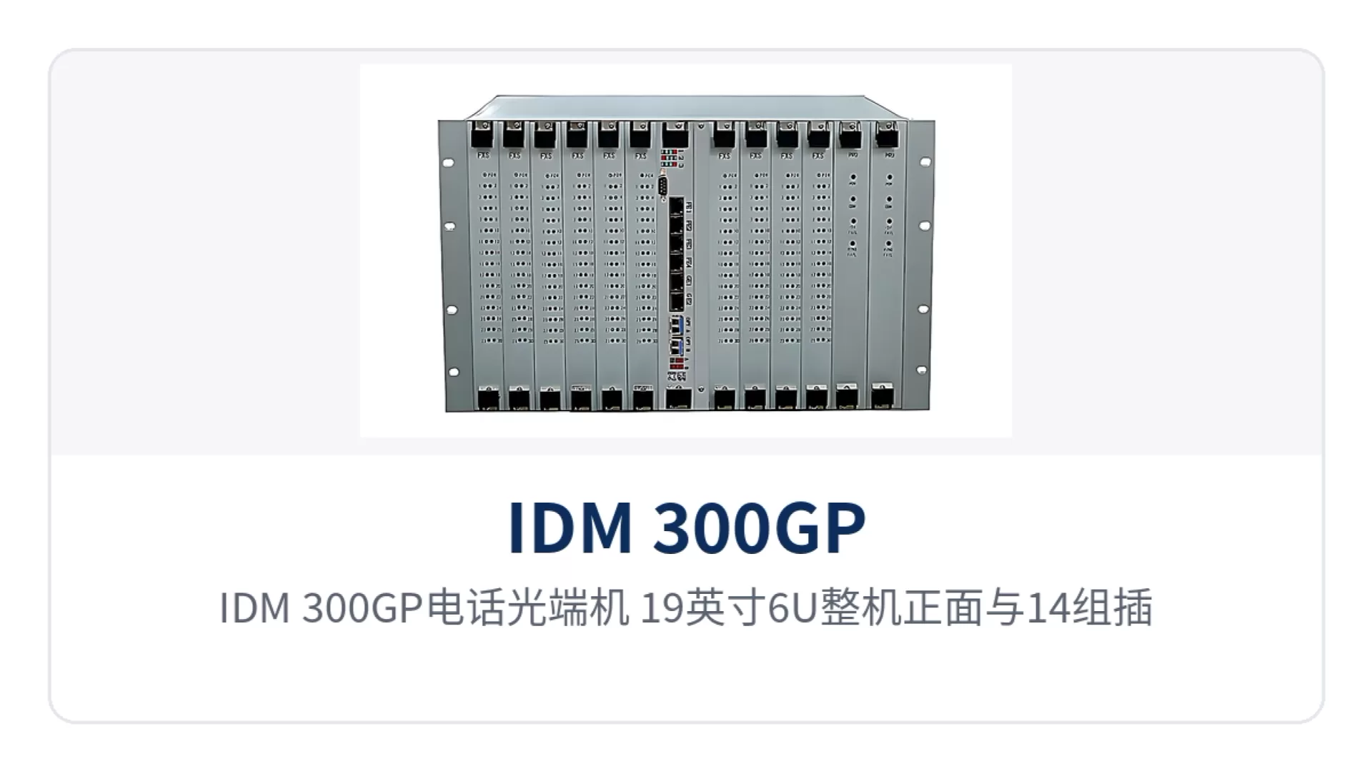
Figure 1: IDM 300GP telephone optical multiplexer 19-inch 6U unit front view with 14 card slots, power and alarm indicator LEDs
What services can one device carry
IDM 300GP telephone optical multiplexer collects three types of services—telephone, E1, and Ethernet—into the same chassis, and can optionally be equipped with narrowband data interfaces such as co-directional 64K, EM2/4-wire, V.24, and V.35 according to the service list, making it a typical multi-service optical multiplexer. The table below lists each item by function and capability description; on-site configuration verification can be done row by row and calculated together with the number of chassis card slots.
| Function | Description |
|---|---|
| 2 isolated gigabit interfaces | Provides 2 RJ-45 gigabit Ethernet interfaces, 10M/100M/1000M adaptive, the two channels are completely isolated at the physical layer, service network and video surveillance network are transmitted over the same fiber without affecting each other, and the gigabit network optical multiplexer capability meets broadband access requirements |
| 8 groups of E1 transparent transmission | Provides 8 groups of E1 transparent transmission interfaces, impedance 75 Ω/120 Ω selectable, frame structure and service content are not rewritten during transmission |
| 30 channels/card telephone access | Each service card accesses 30 channels of 64K telephone audio service, and 10 service cards in full configuration reach 300 telephone channels |
| Caller ID FXO/FXS | FXO and FXS interfaces support caller ID (CID) and can connect to analog telephones, fax machines, and switching equipment |
| 2.5G SFP optical port | Optical line rate 2.5Gbps, SFP optical interface, 20 km transmission as standard configuration, can be extended by replacing with long-distance optical modules |
| Card-based hot-swappable expansion | All 14 card slots support hot-swappable operation; voice channels are added in steps of 30 channels per service card, while chassis, backplane, and main control card configuration remain unchanged |
| 1+1 mutual backup power supply | 2 power cards back up each other; when one power card fails, the other continues to supply power to the chassis |
| 6U centralized chassis | 19-inch standard 6U chassis, dimensions 482×266×270 mm, compliant with telecom and carrier standards, maintained by card slot positioning |
How do 2 isolated gigabit interfaces and 8 groups of E1 share one fiber with telephones
The 2 gigabit Ethernet interfaces enter the 2.5Gbps optical line through independent channels, which is the basic way IDM 300GP telephone optical multiplexer carries broadband services. The two RJ-45 interfaces each occupy an independent channel and are completely isolated at the physical layer, with rates of 10M/100M/1000M adaptive, compliant with IEEE802.3, and supporting Adaptive half-duplex/full-duplex. When the service network and video surveillance network are transmitted over the same fiber, there is no packet-level interworking path between the two networks. Raytrans adopts a physical isolation scheme in the channel design of this gigabit network optical multiplexer to ensure security when multiple networks coexist.
There are 8 groups of E1 channels in total, with a bit rate of 2.048Mbps, HDB3 line code, PCM30/32 frame structure, channel-associated signaling (CAS), compliant with ITU-T G.703. The interface impedance is configured as 75 Ω or 120 Ω, operating in transparent transmission mode, and the original frame structure and service content are not rewritten during transmission, allowing direct connection with existing PCM and SDH equipment. This PDH optical multiplexer-level E1 transparent transmission capability enables the device to smoothly interconnect with traditional transmission networks.
Telephone voice is compressed into a 64Kbit/s bit stream according to ITU-T G.711 A-law, with an audio range of 300 Hz to 3400 Hz, a loop current of 20 mA/channel, and an interface impedance of three-element complex impedance 200 Ω+560 Ω//0.1 μF. The exchange side is accessed through FXO interfaces, and the user side is provisioned through FXS interfaces; both interface types support caller ID (CID).
Voice channels are organized into time slots according to the PCM30/32 format and then multiplexed together with Ethernet packets and 8 groups of E1 channels into a single 2.5Gbps optical line, and the peer end demultiplexes them according to the same format to restore analog voice. Narrowband voice and broadband data each occupy independent channels on the same optical fiber, and services do not squeeze each other's bandwidth, providing a feasible path for telephone, data, and video transmission over the same fiber in a government private network optical fiber communication solution.
Technical Specifications
Parameters are listed in four groups: optical interface, Ethernet and E1 voice interfaces, optional narrowband data interfaces, and power supply and environment. During selection, first determine the optical module by transmission distance and wavelength, then determine the number of card slots and interfaces by the service list, and verify on-site settings against the actual interface type of the peer device. As a professional optical multiplexer manufacturer, Raytrans fully discloses the following parameters in the product showcase for engineering selection comparison.
Optical Interface Parameters
The optical port is an SFP slot, with a receive/transmit rate of 2.5Gbps, 20 km transmission as the standard distance, and the link budget calculated from transmit optical power and receiver sensitivity. Wavelengths are configured in transmit/receive pairs, and long-distance optical modules can be used for long-distance or WDM scenarios. The optical interface design of this optical multiplexer takes into account the transmission requirements of both telephone optical multiplexers and gigabit network optical multiplexers, and the same optical path calculation applies in multi-service optical multiplexer scenarios.
| Item | Parameter/Specification | Description/Applicable Conditions |
|---|---|---|
| Interface type | SFP | Optical module selected by transmission distance and wavelength |
| Fiber mode | Single-mode (multimode optional) | Selected according to on-site optical cable conditions |
| Receive/transmit rate | 2.5Gbps | Optical line rate |
| Receive/transmit wavelength | 1310nm/1550nm | Configured in transmit/receive pairs |
| Transmit optical power | -12~-6dBm | Output optical power at the transmit side |
| Receiver sensitivity | Better than -32dBm | Lower limit of normal operating optical power at the receive side |
| Transmission distance | 20Km | Long-distance optical modules can be optionally installed for longer optical fiber transmission |
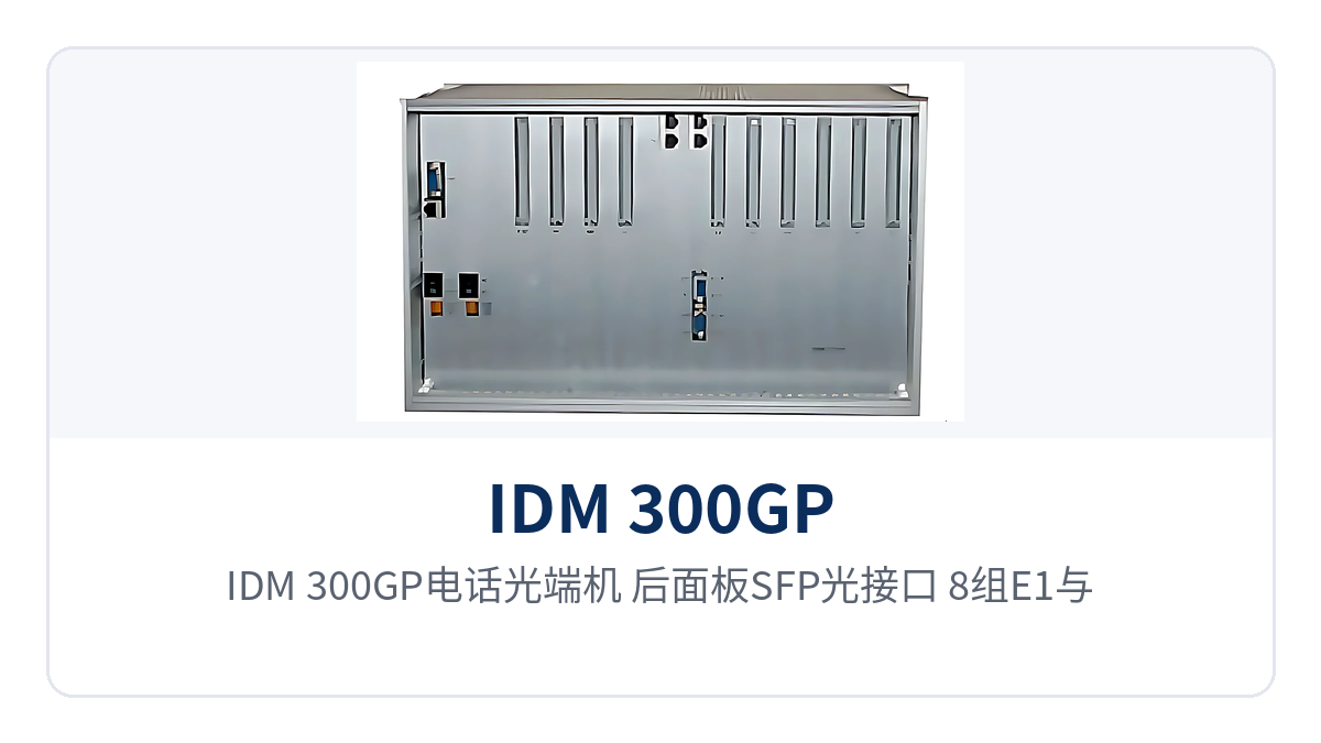
Figure 2: IDM 300GP telephone optical multiplexer rear panel layout of SFP optical interfaces, 8 groups of E1 and dual gigabit Ethernet interfaces
Ethernet, E1 and Voice Interface Parameters
The three types of interfaces—Ethernet, E1, and FXO/FXS—form the service access side of the site, and parameters are listed by interface. E1 impedance and Ethernet rate are set on site according to the peer device, and voice interface parameters determine the connection quality between telephones and switching equipment. The service access of gigabit network optical multiplexers and multi-service optical multiplexers is based on this group of interfaces, and PDH optical multiplexer users can also refer to them when upgrading.
| Item | Parameter/Specification | Description/Applicable Conditions |
|---|---|---|
| Ethernet interface type | RJ-45 | Electrical interface, 2 physically isolated channels |
| Ethernet transmission rate | 10M/100M/1000M | Wire-speed 1000M, adaptive |
| Ethernet standard protocol | Supports IEEE802.3 | Operating mode Adaptive half-duplex/full-duplex |
| E1 bit rate | 2.048Mbps | HDB3 line code |
| E1 standard protocol | Supports ITU-T G.703 | Impedance 75 Ω/120 Ω selectable |
| E1 frame structure and signaling | PCM30/32, channel-associated signaling (CAS) | Transparent transmission mode, original frame structure not rewritten |
| E1 interface configuration | 8 groups | Select 75 Ω or 120 Ω according to peer interface impedance |
| Voice audio range | 300 Hz~3400 Hz | Compression ITU G.711 A-law |
| Voice interface impedance | Three-element complex impedance 200 Ω+560 Ω//0.1 μF | Loop current 20 mA/channel |
| Caller ID | Supported by both FXO and FXS | Connects to analog telephones, fax machines, and switching equipment |
Optional Narrowband Data Interface Parameters
Co-directional 64K, EM2/4-wire, V.24, and V.35 interfaces are optionally configured according to the service list, and are used for relay protection signals, telecontrol channels, serial port data, and leased line equipment access. The parameters of each interface and the recommendations they follow are listed item by item in the table below; verify against the peer device interface type before wiring. Narrowband data access for relay protection and telecontrol channels in a government private network optical fiber communication solution is often implemented by selecting this group of interfaces.
| Interface | Parameter/Specification | Description/Applicable Conditions |
|---|---|---|
| Co-directional 64K | Line code G.703, bit rate 64Kbps, impedance balanced 120 Ω | Fully compliant with ITU G.703 recommendation |
| EM2/4-wire | Audio 300 Hz~3400 Hz, impedance balanced 600 Ω, G.711 A-law | Return loss no less than 18 dB |
| V.24 | Asynchronous ≤9600bps, synchronous 64Kbps | Electrical characteristics compliant with CCITT V.28 protocol |
| V.35 | RJ-45, n×64Kbps (n=0~31) | Compliant with ITU-T V.35 recommendation, terminal interface compliant with ISO2593 |
Power Supply, Environment and Chassis
The power supply mode is AC220V or DC-48V, with overall power consumption ≤90 W, and both the AC mains in the equipment room and the DC -48V of the communications power supply can be directly connected. Operating temperature -10℃~+50℃, relative humidity 0~95% (non-condensing), suitable for indoor equipment rooms and attended communications stations. Raytrans also provides the enclosure dimensions in the product showcase to facilitate cabinet space reservation.
| Item | Parameter/Specification | Description/Applicable Conditions |
|---|---|---|
| Power supply mode | AC220V/DC-48V | Selected according to equipment room power conditions |
| Overall power consumption | ≤90 W | In full configuration |
| Operating temperature | -10℃~+50℃ | Indoor equipment rooms and communications stations |
| Relative humidity | 0~95% (non-condensing) | Avoid condensation environments |
| Dimensions | 482×266×270 mm (Length×Depth×Height) | 19-inch standard 6U chassis |
How does the card-based structure expand from 30 channels to 300 channels
The capacity expansion basis is the number of voice channels actually provisioned at the site. Service cards are added in increments of 30 channels, and the initial configuration need not be fully populated. With 10 service card slots populated, the chassis is fully configured at 300 telephone channels; 2 main control card slots and 2 power card slots are configured as standard, which closes the configuration accounting for the 14 card slots. Project implementation proceeds in the order below, with installation, wiring, and service card addition carried out as three separate steps. The same card-based telephone optical multiplexer architecture also applies to service card expansion of multi-service optical multiplexers.
- Chassis positioning: secure the chassis in the cabinet using 19-inch 6U space, and position the backplane and wiring area according to the construction drawings.
- Optical path termination: configure SFP optical modules in pairs according to transmission distance and wavelength, and connect the terminated single-mode fiber (multi-mode optional) to the optical port.
- Insert the main control card and power cards: insert the main control card and 2 power cards, and select AC220V or DC-48V power supply according to on-site conditions.
- Insert service cards according to the voice channel list: each service card adds 30 telephone channels, and populating all 10 cards gives the full configuration of 300 telephone channels.
- Interface matching: connect FXO to the exchange side and FXS to user telephones, select 75Ω or 120Ω for the 8 E1 groups, and connect the 2 gigabit ports to data equipment.
- Power-on verification: observe the card slot alarm indications, verify the number of voice channels enabled on each card and the interface correspondence, and record the results for archiving.
After voice channel growth, capacity expansion still means adding cards: the chassis with vacant service card slots continues in use, cards are added in increments of 30 channels per card, and the chassis, backplane, main control card, and power card configuration remain unchanged. Capacity planning is calculated at 300 telephone channels per chassis; beyond this scale, plan the number of chassis and site distribution separately, as expansion does not require replacing the entire unit. For sites in a government private network optical fiber communication solution where voice channels are provisioned in phases, cards can be added in batches and put into operation in this manner.
How Far Can a 2.5G SFP Optical Port Transmit over 20 km, and What If That Is Not Enough?
The standard model is configured for 20 km transmission. The link budget derives from a transmit optical power of -12 to -6 dBm and a receiver sensitivity better than -32 dBm; in engineering practice, the margin is calculated after deducting the optical modules at both ends, the mating connectors, and the optical cable attenuation item by item. Single-fiber bidirectional transmission occupies only one fiber core, saving half the number of cores in scenarios where fiber is leased over long distances. When gigabit network optical multiplexers and PDH optical multiplexers are deployed in hybrid networking, the optical port budget is still calculated section by section according to the parameters of this unit.
When the distance exceeds 20 km, replacing the modules with long-distance optical modules extends the transmission distance without changing the chassis or service cards. Multi-site projects can also work with other equipment to form chain networks, ring networks, and point-to-multipoint star networks, so that when the optical path at one point fails, services can be rerouted from the other direction. Raytrans often deploys such optical multiplexers in chain or ring topologies in government private network optical fiber communication solutions to improve private network link reliability.
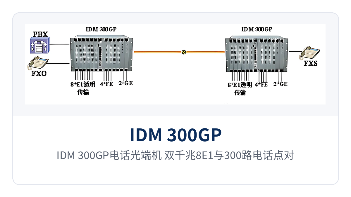
Figure 3: IDM 300GP telephone optical multiplexer — dual gigabit, 8 E1, and 300 telephone channels in point-to-point and chain network networking schematic
Typical Application Scenarios
The IDM 300GP telephone optical multiplexer addresses three types of scenarios: electric power private networks, rail transit communication, and military and government private networks. What they share is distributed sites, mostly unattended, where voice and data must be backhauled over the same path. The following three scenarios are described separately in terms of service access mode, card slot configuration, and O&M actions, so that the product showcase configuration can be checked by project type.
Electric Power Private Network: Substation Dispatch Telephone and Telecontrol Data Backhaul over One Fiber
Substations in an electric power private network are distributed along the line. Within a station, dispatch telephone service must remain continuously available, and telecontrol data and video surveillance must be backhauled to the dispatch center. The IDM 300GP telephone optical multiplexer performs centralized access on the substation side; DC-48V power can be taken directly from the station's DC distribution panel and shared with the communications power supply, so no separate AC circuit is required.
Dispatch and administrative telephones are provisioned through FXS interfaces, trunks to the dispatch center are extended through 8 E1 groups, and telecontrol data and surveillance backhaul each use one of the 2 isolated gigabit ports, keeping the two networks independent at the physical layer. The number of voice channels is configured in tiers according to site traffic; hub substations are planned at the full configuration of 300 telephone channels, and the 30-channel-per-card increments leave room for subsequent growth.
Rail Transit: Telephone and E1 Channel Extension for Stations and Section Duty Points
Stations, depots, and section duty points in rail transit are distributed along the line. The number of telephones varies considerably with station class, and E1 channels are also needed between stations to carry dedicated communication services. The IDM 300GP telephone optical multiplexer is configured according to site traffic in a card-based manner at 30 telephone channels per card: small stations start with one service card, while interchange stations and depots add cards as required.
The 20 km transmission capability allows single-mode fiber to cover adjacent stations along the line; inter-station trunks are extended through 8 E1 groups, and station service data and video backhaul use the 2 gigabit Ethernet ports. The 19-inch 6U chassis facilitates unified installation in the communications equipment room, spare cards are replaced by card slot, and maintenance at unattended section sites is mainly card replacement.
Military and Government Private Networks: Independent Networking of Duty Post Telephones and Private Network Data
Communications between duty posts, duty points, and command nodes in military and government private networks are organized independently over the private network, with clear requirements for call availability and link independence. The IDM 300GP telephone optical multiplexer performs centralized access on the duty post side: the exchange side interfaces with switching equipment through FXO interfaces, the user side completes subscriber line provisioning through FXS interfaces, and voice is encoded with G.711 and transmitted over the 2.5Gbps channel.
The 2 isolated gigabit ports let the private service network and the supporting network each use an independent channel, with no packet-level intercommunication path between services, so the network boundary does not depend on VLAN partitioning or VPN encapsulation. On-duty personnel locate the faulty card by the front panel alarm indications and card slot numbering, and replacement is completed by fitting a spare card with the matching number; site maintenance actions are mainly card replacement.
Conclusion
The card-based 2.5G telephone optical multiplexer packs 2 isolated gigabit Ethernet ports, 8 transparent E1 groups, and caller ID-capable FXO/FXS voice channels into a single 6U card-based chassis, completing voice, trunk, and data backhaul over one 2.5Gbps fiber, with 20 km transmission meeting long-distance networking needs between adjacent sites.
The IDM 300GP telephone optical multiplexer performs centralized access on the site side in electric power private networks, rail transit communication, and military and government private networks. Its 2.5G SFP optical port allows module replacement by distance, and 30 channels per card are added according to traffic, with both capacity expansion and maintenance handled at the card slot level. Specific card slot configuration, interface type, and optical module selection should be checked against the site service list, and parameters are subject to the manufacturer's technical documentation and commercial confirmation.