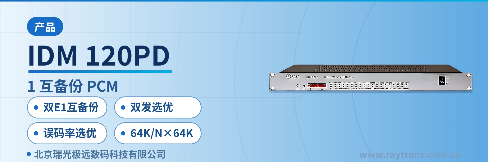
IDM 120PD Dual-E1 Mutual Backup PCM
Dual-transmit selection, bit error rate path selection, services uninterrupted upon single-link degradation
IDM 120PD provides mutual backup transmission services over dual E1 interfaces, suitable for applications where important services are transmitted over two different E1 channels. IDM 120PD adopts the dual-E1 dual-transmit selection mode to select the output E1, and the equipment monitors the two E1 interfaces in real time.
The IDM 120PD-2E1 dual-E1 dual-transmit selective mutual backup equipment is an E1 channel mutual backup transmission device developed by Beijing Ruiguang Jiyuan Digital Technology Co., Ltd. (Raytrans), that is, a PCM equipment for private network communication. It sends the same set of important services into two E1 channels simultaneously and selects the better one at the output side based on line quality. The device is intended for sites in electric power private networks, rail transit, and oil and gas pipelines that require continuous channel availability, so that services do not lose their path when a single E1 link degrades. It can serve as a key node device in an E1 channel mutual backup solution for electric power private networks.
Key Specifications at a Glance: dual-E1 mutual backup · dual-transmit selection · bit error rate selection · 64K/N×64K services · 2 E1 interfaces · real-time monitoring of the lines
What Kind of Device Is the Dual-E1 Dual-Transmit Selective Mutual Backup Equipment?
The IDM 120PD-2E1 is a PCM equipment that uses two E1 channels as mutual backups. It provides two E1 interfaces on the line side and accesses services on the service side at 64K or N×64K granularity. The device sends the same service over both E1 channels at the same time and keeps only the channel with better quality at the output side, so adding or removing a link does not change the service configuration. As a PCM equipment for private network scenarios, its core positioning in the product showcase is dual-channel mutual backup and transparent transmission of services.
An E1 channel runs at 2.048Mbps and transmits with HDB3 line coding as recommended by ITU-T G.703. A frame has 32 time slots of 64Kbps each, where TS0 carries frame alignment, TS16 carries channel-associated signaling (CAS), and the remaining time slots carry services. Services occupy time slots at 64K or N×64K, and multiple narrowband services can share the same E1.
Why Should Services Be Carried Across Two E1 Channels
The reliability of a single E1 channel depends on the optical cables, microwave links, and equipment along the route, and maintenance or degradation at any point interrupts the services on that channel. When important services run over only one channel, the availability of the channel is the availability of the services, and the emergency repair time directly equals the service interruption time.
By sending the same set of services into two E1 channels over different routes at the same time, the services physically have two paths. When one channel is under maintenance, shows rising bit errors, or is interrupted, the other still carries the same services, and the site does not need to rewire or reconfigure the service data.
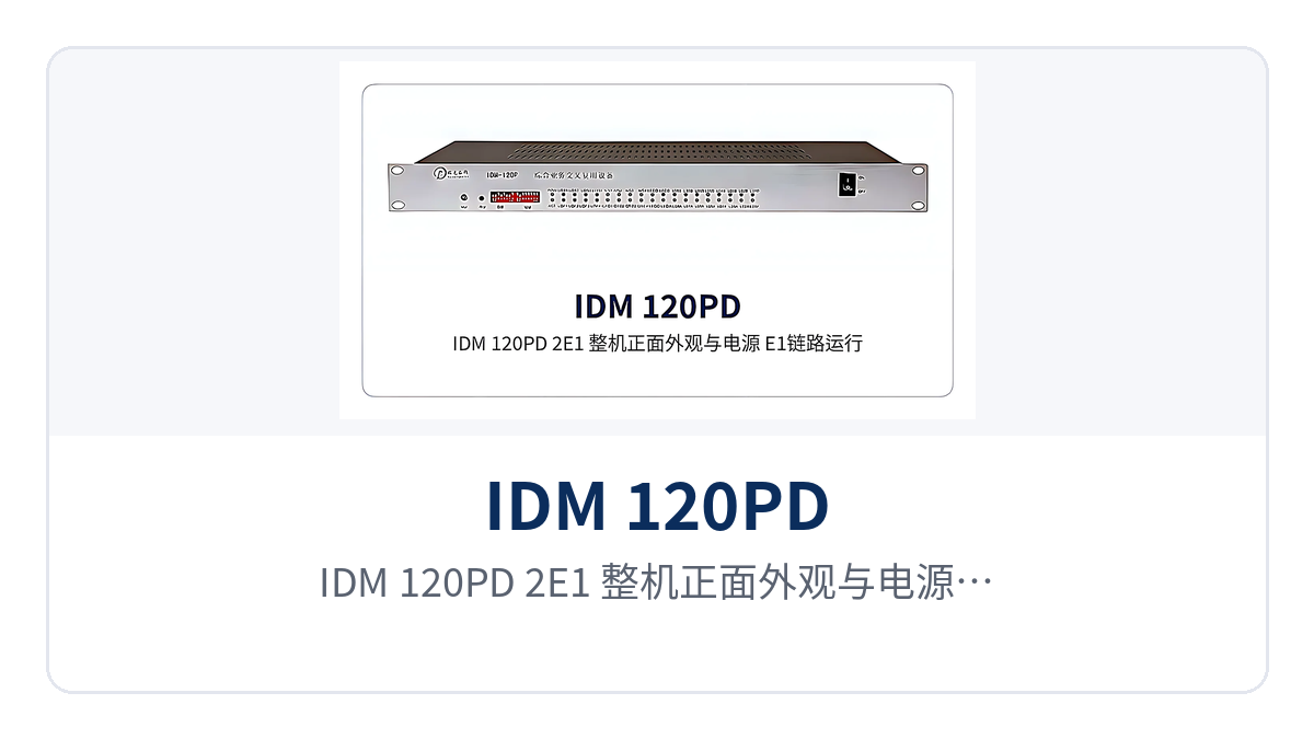
Figure 1: Close-up of the IDM 120PD-2E1 front panel, power supply, and operating indicator LEDs of the two E1 links
How Does Dual-E1 Dual-Transmit Selection Work?
Dual-transmit selection sends the same service out through both E1 interfaces at the same time, with one PCM equipment at each end configured as a pair. The service travels over both channels, each channel carries a complete data stream, and the output side does not wait for the active channel to drop before acting.
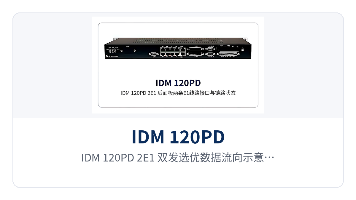
Figure 2: Schematic of the IDM 120PD-2E1 dual-transmit selection data flow, where the same service is sent in parallel over two E1 channels and one is selected at the output side
Selection takes place at the output side. The device monitors the line state of both E1 interfaces in real time and selects the output according to the line bit error rate, so the channel with rising bit errors stops carrying traffic while the other continues to deliver services. The criterion comes from the transmission quality of the channels themselves; when a channel degrades, the output switches first to the better one, and the service side sees a channel change rather than a service interruption.
Should the Two E1 Paths Be Separated
When both E1 channels run over the same optical cable, the same transmission device, or the same power distribution panel, the backup effect is offset by the shared point of failure. A cable cut, a power failure of the same device, or a loss of the same power supply circuit takes down both channels together, and dual-transmit selection has no other channel to select.
In engineering practice, the two E1 channels are assigned to different transmission paths: one over the existing SDH or microwave channel of the site, the other over a leased circuit or another transmission device, with the upstream equipment, power supply circuits, and incoming routes of the two channels kept as separate as possible. Only after the paths are separated does dual-transmit selection have a real second path to use.
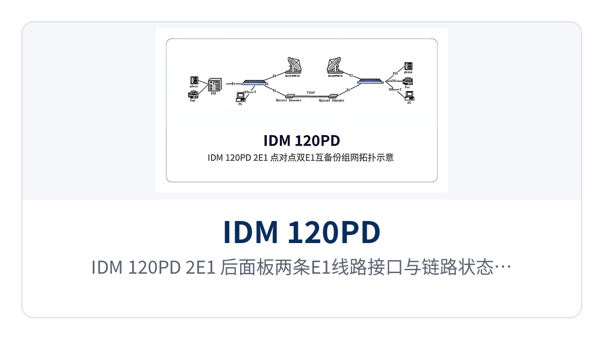
Figure 3: Layout of the two E1 line interfaces and link status indications on the IDM 120PD-2E1 rear panel
Core Functions and Performance Specifications
The functions fall into three parts: dual-E1 channels, selection criteria, and service carrying, listed item by item in the table below. For selection, compare the number of channels and service types required by the project; items not needed can be left unconfigured. The table also gives the location where each function acts on the channel side and the service side, making it easy to check item by item against the ordering configuration sheet.
Function Overview
Function | Description |
|---|---|
Dual E1 interfaces | Two E1 interfaces on the line side, so the same set of services can be sent over both channels at the same time |
Dual-transmit selection | Services are sent over both E1 channels at the same time, and the output side selects one of the two channels |
Real-time monitoring of the lines | Continuously monitors the line state of both E1 interfaces, and link changes are reflected on the device side immediately |
Bit error rate selection | Selects the output channel based on the line bit error rate, and the channel with rising bit errors stops carrying traffic |
64K service carrying | Carries a single narrowband service in a 64K time slot, with multiple services sharing the same E1 |
N×64K service carrying | Occupies consecutive time slots at N×64K to carry data-type services with higher bandwidth requirements |
Channel mutual backup | The two E1 channels back each other up, and when one channel is interrupted the other continues to transmit the services |
Technical Specifications
The parameters are listed in three groups: E1 interfaces, service carrying, and device configuration. Items not given in the documentation are confirmed by the ordering configuration and are not inferred from other models in the same series. If the supplied configuration of a project differs from this table, the ordering configuration sheet shall prevail, and the items shall be checked one by one against the sheet before the equipment is put into operation on site.
Item | Parameter/Specification | Description/Applicable Conditions |
|---|---|---|
Device Model | IDM 120PD-2E1 | Dual-E1 channel mutual backup equipment |
Number of E1 interfaces | 2-channel | The two channels are configured as a pair and back up each other |
E1 rate | 2.048Mbps | E1 base group rate, in accordance with ITU-T G.703 |
E1 line coding and frame structure | HDB3, PCM30/32 frame structure | Interconnects with existing E1 transmission networks and switching equipment |
Service granularity | 64K, N×64K | Narrowband services and bandwidth-type services share the two E1 channels |
Backup mode | Dual-transmit selection | The same service is transmitted over both E1 channels simultaneously, and one is selected at the output side |
Selection criterion | Line state and bit error rate | The device selects the output according to the E1 bit error rate; the channel with the higher bit error rate is dropped |
Service-side interface type and number of channels | Not yet recorded in the knowledge base | Subject to the ordering configuration sheet |
Power supply mode and overall power consumption | Not yet recorded in the knowledge base | Subject to the technical documentation supplied with the unit and the ordering configuration |
Dimensions and operating environment | Not yet recorded in the knowledge base | Subject to the technical documentation supplied with the unit and the ordering configuration |
Differentiated Capabilities and On-Site Value
The correspondence between the three differentiated capabilities and on-site problems at the site is shown in the table below. The left column lists the capabilities of the device, and the right column lists the specific problems these capabilities solve. During selection, compare them item by item according to site conditions; capability items that are not needed can be left unconfigured. The specific configuration is subject to the commercial confirmation sheet.
Differentiated Selling Point | Value on Site |
|---|---|
Dual-E1 dual-transmit selection | Important services are transmitted with mutual backup across two different E1 channels. When either channel degrades, the output side switches to the other one for carrying, and service data does not need to be reconfigured as the link changes. This is a typical implementation in the E1 channel mutual backup solution for electric power private networks. |
Real-time monitoring and bit error rate selection | The device monitors the state of the two E1 lines in real time and automatically selects the output according to the bit error rate. Channel quality degradation is reflected in the selection result before services are affected. |
64K and N×64K multi-service | Supports multiple services at 64K and N×64K, adapting to narrowband service carrying in private networks. Existing voice and data services can be accessed without modification. |
As an optical multiplexer manufacturer, Raytrans provides PCM equipment that matches scenario requirements such as government private network optical fiber communication solutions and military emergency communications vehicle solutions. The above dual-E1 mutual backup capability can directly serve private network users with high requirements for channel reliability.
Typical Application Scenarios
IDM 120PD-2E1 is designed for private network sites with limited channel resources and high service importance. The structure is the same across the three industries: one PCM equipment at each end, connected by two E1 channels in the middle, with services configured symmetrically at both ends. The difference lies in the service types and the sources of the two E1 channels.
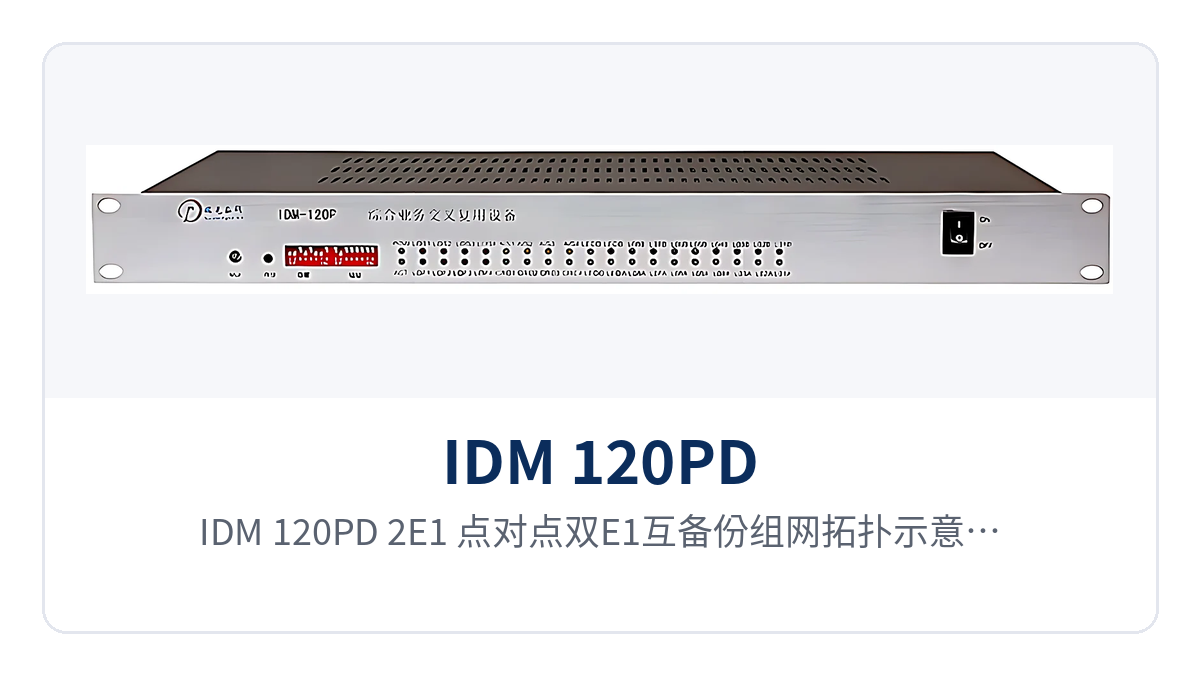
Figure 4: IDM 120PD-2E1 point-to-point dual-E1 mutual backup networking topology schematic, with devices at both ends interconnected through two E1 channels
Electric Power Private Network: Dispatch Telephone and Telecontrol Data Mutual Backup Across Channels
Between a substation and a dispatch center, there are usually two types of services at the same time: dispatch telephone and telecontrol data, with E1 channels provided by transmission equipment. Dispatch telephone relates to the issuance of on-site operating commands, and telecontrol data relates to the reporting of power grid operating status. Neither type of service can afford long interruptions. Raytrans's E1 channel mutual backup solution for electric power private networks is designed for such scenarios, implementing dual-channel redundant carrying through PCM equipment.
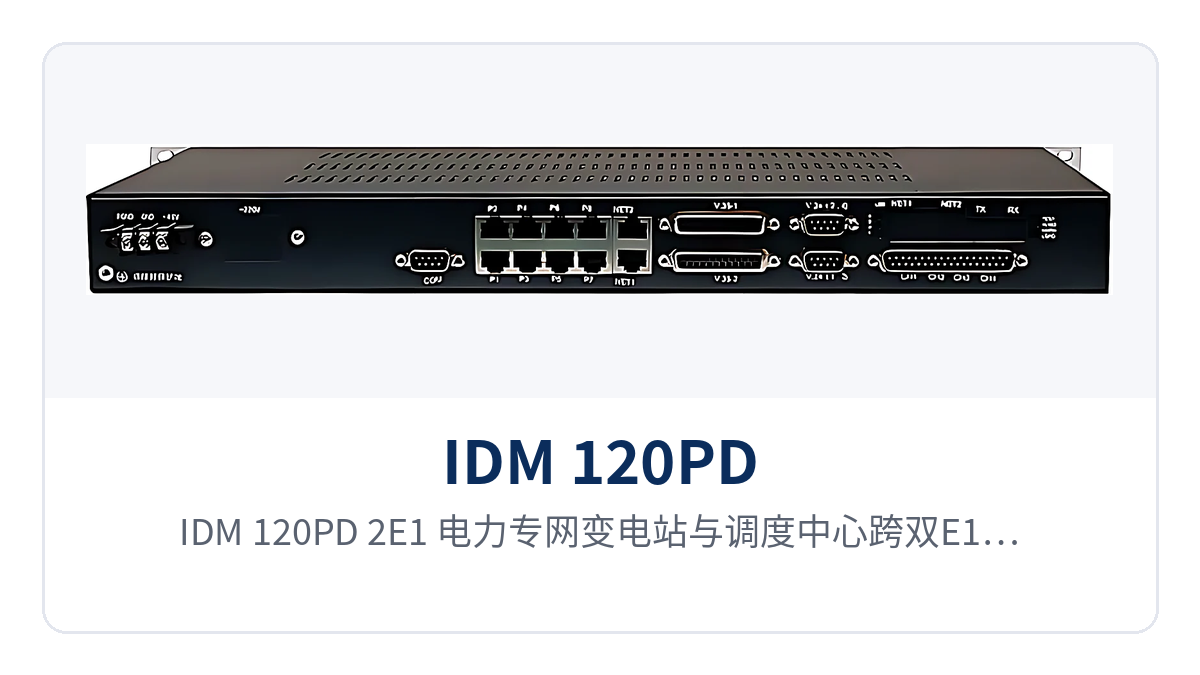
Figure 5: IDM 120PD-2E1 deployment schematic for mutual backup across dual E1 channels between a substation and a dispatch center in an electric power private network
Dual-E1 dual-transmit selection keeps important services uninterrupted through cross-channel mutual backup: when one E1 channel is under maintenance or its bit error rate rises, the output side switches to the other one, and the dispatch console's calls and the master station's telemetry continue to be transmitted. Only when the two E1 channels come from different transmission devices or different routes does the backup cover a single point of failure.
Rail Transit: Section Site Services Selected Between Two E1 Channels
In rail transit, section equipment rooms, stations and depots are distributed along the line. Channels from sections to stations are mostly provided by the existing transmission network, and often only a small number of E1 channels are reserved in the equipment room. Section services are mainly dispatch telephone, broadcast audio and signal monitoring data. Channel interruption directly affects train operations and station staff communication.
Real-time monitoring of the bit error rates of two E1 channels and automatic selection of the optimal output ensure smooth communication: the PCM equipment sends section services over both E1 channels simultaneously. The channel with the rising bit error rate is dropped from carrying, and the other one continues to carry services. Cabinet space and maintenance windows in section equipment rooms are limited, and the link criterion is monitored by the device itself, so on-duty personnel do not need to log in to the network management system segment by segment for troubleshooting.
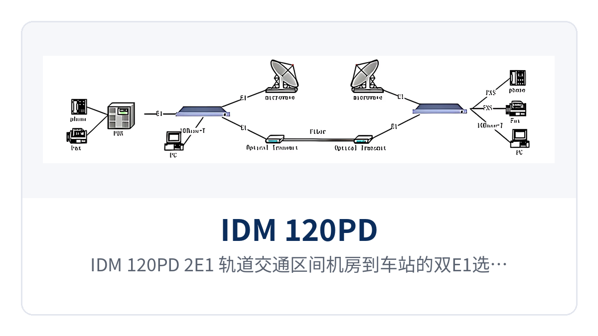
Figure 6: IDM 120PD-2E1 dual-E1 selection access schematic from a rail transit section equipment room to a station
Oil and Gas Pipeline: Narrowband Services at Valve Chambers and Stations over Dual E1 Channels
Valve chambers, cathodic protection stations and metering stations of oil and gas pipelines are distributed along the pipeline. The sites are unattended and far away, and channels are mostly provided by the transmission system along the pipeline. Site services are mainly valve chamber monitoring data, dispatch telephone and combustible gas alarm signals. The number of channels is small, but continuity requirements are high.
Dual-E1 mutual backup and 64K/N×64K multi-service make private network transmission more reliable: valve chamber monitoring data occupies time slots at N×64K bandwidth, and dispatch telephone occupies 64K. The two types of services share the two E1 channels. Unattended sites have long emergency repair cycles. When a channel problem occurs, services are first carried by the other channel, and the service path is already restored before O&M personnel arrive at the site.
Figure 7: IDM 120PD-2E1 dual-E1 channel access schematic for narrowband services at an unattended valve chamber of an oil and gas pipeline
Conclusion
As a dual-E1 dual-transmit selective mutual backup equipment, IDM 120PD-2E1 integrates the mutual backup and selection of two E1 channels into one unit: the same batch of important services is transmitted over both channels simultaneously, the device monitors line states in real time and selects the output according to the bit error rate, and when one channel degrades or is interrupted, services continue to be carried by the other one.
The device supports multiple services at 64K and N×64K, adapting to narrowband service carrying in electric power private networks, rail transit and oil and gas pipelines. As an optical multiplexer manufacturer, Raytrans also has mature PCM equipment engineering experience in government private network optical fiber communication solutions and military emergency communications vehicle solutions, and its product showcase covers a variety of private network communication scenarios from narrowband access to optical fiber transmission.
During selection, first confirm whether the two E1 channels can belong to different transmission paths, and then determine the interface type and number of channels according to the service list. Check power supply, power consumption and installation conditions against the technical documentation supplied with the unit and the ordering configuration sheet, and also verify the upstream equipment and power supply circuits of the two E1 channels.