
Power Line Inspection Management System
Power line inspection technology is developing rapidly, with robots traveling along overhead lines and inspection…
Power Line Inspection Management System
I. Overview
Power line inspection technology is developing rapidly, with robots traveling along overhead lines and inspection drones. With urban development, power cables are increasingly being transferred to underground transmission. Since there is no GPS signal underground, inspection robots typically use dedicated positioning base stations, such as WiFi and Bluetooth base station positioning, which offer relatively low positioning accuracy, usually with errors of 3 to 10 meters. UWB positioning can achieve centimeter-level accuracy, but the cost is relatively high, typically around 1,000 RMB per base station. RFID and QR code tags can be used for auxiliary positioning through robot vision processing.
Power line inspection needs to evolve toward smart inspection, including IoT technology, big data technology, and GIS-based technologies.
II. Smart Inspection APP
Smart inspection provides outdoor inspection work management.
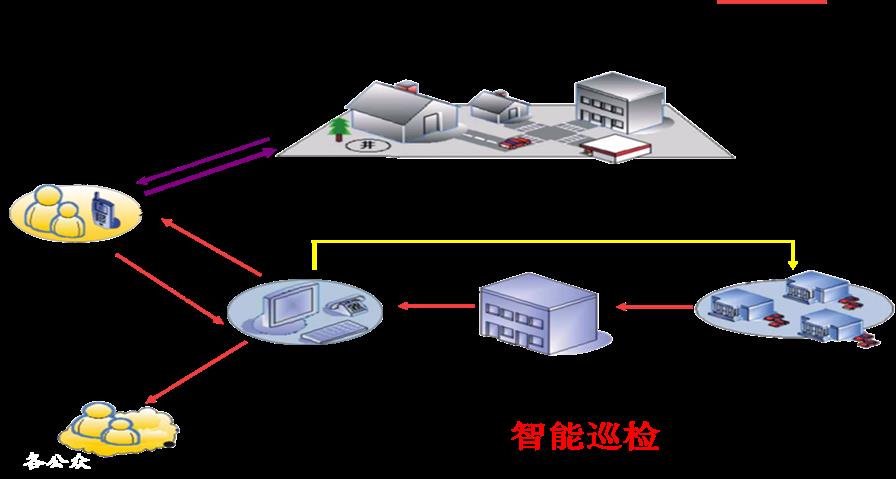

To achieve underground robot inspection, operators need to provide detailed initialization settings, such as operator information, initial configuration, task settings, operation records, etc. These need to be connected to the database system via a mobile APP.
The surface GIS system uses GPS positioning, covering utility poles, distribution boxes, cable manhole covers, etc., including the cable routing of the surface section.
III. RFID Management and Positioning Technology
The underground section uses RFID tag positioning. RFID is a passive positioning technology with relatively poor accuracy; QR codes are sometimes used as auxiliary means to achieve precise positioning.
To improve RFID accuracy, smaller RFID tags can be used, and the transmission power of the RFID scanning module can also be reduced. To distinguish different cables, tags for different cables need to be placed at a certain distance apart, etc.

According to relevant regulations, electronic tags must be installed on cable intermediate joints and cable manholes (including buried manholes). RFID tags must be resistant to high temperature, abrasion, corrosion, and water, etc.
IV. IoT Devices
To achieve underground positioning, it is necessary to introduce the ID2000.
Another device is the IOT365 IoT fixed desktop device. The IOT365 IoT device provides collection and management of various sensor signals, such as temperature and humidity, light intensity, explosive gas detection, carbon dioxide detection, smoke detection, personnel activity detection, sump water level detection, etc. The collected data is sent to the central database via WiFi network. All this information is transmitted to the central GIS platform, where the central system processes it and generates alarm and control information.

IOT365 provides relay control outputs, which can control high-power devices, high-voltage devices, or AC devices.
Meanwhile, IOT365 provides high-speed VMOS switch power transistor circuits, which can control stepless dimming of lights via PWM control, and can also control stepless speed regulation of DC motors.

V. GIS Platform
The central GIS platform uses the independently developed 3D GIS platform and database system, saving users a significant amount of cost in purchasing GIS and database software.
The GIS platform provides outdoor 3D display and indoor vector map display.
Camera information is usually also available, and image analysis is performed in the background. All this data is stored in the database. Image information can also be used for AR-enhanced GIS management.


GIS Platform Functions:
The GIS system supports roaming, zoom in, zoom out, and other display functions;
Hierarchical organization and display of power facility models;
Basic information search and positioning functions for user convenience;
Provides new layers for transmission lines, with the ability to modify line coordinates and attributes;
Provides line query and statistics functions, including spatial query, fuzzy query, conditional query, topological query, along-line statistics, query result output, etc.
Has landmark annotation functions, divided into point landmarks, current landmarks, and area landmarks. Can save user-drawn vector data.
Resource Management Tree:

VI. Database Technology
Power line database system:
Power facilities: substations, power plants, power lines, towers, switching stations, distribution boxes, ring main units, transformers, etc. Including related parameters, image information, location information, usage information, etc.
Tower database: associated line, tower number, tower type, call height, connection position, access position, exit position, tower photos.
Cable path data: substation, line name, cable segment name, cable segment sequence number, length, model, status, laying method, burial depth (elevation), routing, voltage level, starting point, inflection point, endpoint coordinates, intermediate joint coordinates, installation location, image data, cable path diagram, cable single-line diagram, electrical bay diagram, etc.
VII. GIS-Based Visualization Technology
On the GIS platform, frequently monitored parameters are queried and displayed.
Real-time query of RFID data scanned in underground pipe galleries, displaying archive data and location data;
Display of other information transmitted back by inspection robots;
Real-time display and alarm processing of environmental monitoring IoT data;
The GIS platform is directly connected to the emergency command and dispatch platform for coordinated dispatch of manpower, vehicles, and other resources;

FAQs
What Is the Definition of Communication?
Communication: the exchange and transmission of information between people, or between people and nature…
View answerWhat is the difference between optical fiber and optical cable? What are the common optical fiber connectors?
Optical fiber is a medium that transmits information from one end to another. It is a glass or plastic fiber that…
View answerWhat is the difference between single-fiber and dual-fiber?
The biggest difference between single-fiber and dual-fiber optical terminals lies in the optical modules on their…
View answerWhat is E1? How to Use E1
What is E1 The European 30-channel pulse code modulation PCM is abbreviated as E1, with a rate of 2.048Mbit/s.
View answerPCM30 Working Principle: What Is PCM30/32
PCM30 Equipment Working Principle The 30-channel PCM equipment refers to equipment that provides 30 user interfaces and…
View answer