
IDM网管系统说明
第一章 系统简介1.1、 系统概述: IDM 系统采用NetGuard为其网络管理平台,通过控制盘实现统一网管,网管可管理的项目有:a. 查询设置网络主机状态、网络拓扑、工作状况
Gallery
title: "IDM Network Management System Manual"
model: "IDM"
category: "Bridge Converter"
tags:
- "Raytrans Network Management Manual"
- "IDM Network Management"
- "Network Management System Manual"
description: "Chapter 1 System Introduction 1.1 System Overview: The IDM system adopts NetGuard as its network management platform, enabling unified network management through the control panel. The network management system can manage the following items: a. Query and set network host status, network topology, working conditions, and overall alarm status"
cover: "/images/imports/img-3c43dd3a.webp"
images: - "/images/imports/img-3c43dd3a.jpg"
- "/images/imports/img-7fb8dab5.jpg"
- "/images/imports/img-0a091de8.jpg"
- "/images/imports/img-37d65a55.jpg"
- "/images/imports/img-77917234.jpg"
- "/images/imports/img-8a58c241.jpg"
- "/images/imports/img-06af6bdc.jpg"
- "/images/imports/img-a543a963.jpg"
- "/images/imports/img-922ec368.jpg"
- "/images/imports/img-28fc6d07.jpg"
- "/images/imports/img-b1919a71.jpg"
- "/images/imports/img-60641f7b.jpg"
- "/images/imports/img-43978894.jpg"
- "/images/imports/img-8ab624b3.jpg"
- "/images/imports/img-5cebbb39.jpg"
- "/images/imports/img-5f1abe4b.jpg"
- "/images/imports/img-cbdbad44.jpg"
- "/images/imports/img-71b14e7b.jpg"
- "/images/imports/img-6365de96.jpg"
- "/images/imports/img-db2327a2.jpg"
- "/images/imports/img-5315591d.jpg"
- "/images/imports/img-6ec07fc6.jpg"
- "/images/imports/img-563ae823.jpg"
- "/images/imports/img-43cce1bc.jpg"
- "/images/imports/img-62a9bb39.jpg"
- "/images/imports/img-833cdecf.jpg"
- "/images/imports/img-93843ffa.jpg"
- "/images/imports/img-41e282ec.jpg"
- "/images/imports/img-082a72f9.jpg"
- "/images/imports/img-340df5bf.jpg"
- "/images/imports/img-527937c0.jpg"
keywords: "Raytrans Network Management Manual,IDM Network Management,Network Management System Manual"
slug: "idm-8"
publishDate: "2026-05-12"
Chapter 1 System Introduction
1.1 System Overview
The IDM system adopts NetGuard as its network management platform, enabling unified network management through the control panel. The network management system can manage the following items:
a. Query and set network host status, network topology, working conditions, and overall alarm status
b. Query the type, working conditions, and overall alarm status of each card
c. Set and query E1 alarm masking for each tributary
d. Set the automatic query function
e. Set and query DXC connection assignment for 4 E1 timeslots
f. Set and query 30-channel plug-in card services and N*64K services
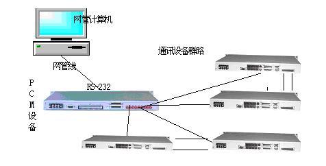
The overall block diagram of the network management system is as follows:
@@IMG0@@
Figure 1
1.2 Hardware Requirements
Host: PC-compatible computer, serial port must be functional;
CPU: 586 or above;
Memory: 64M or above;
Video Memory: 2MB or above;
Monitor: 17" color monitor;
Hard Disk: 2G or above;
Operating System: Windows 95/98/2000/XP
1.3 Connection Method with Transmission Equipment
The network management computer connects to the transmission equipment via a serial port (COM1 or COM2). Schematic diagram (as shown in Figure 2)
@@IMG1@@
Figure 2
Chapter 2 Installation
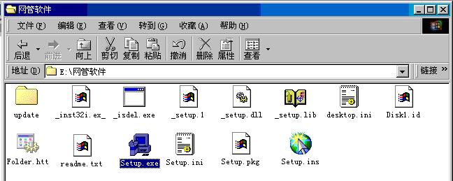
2.1 Step 1: The network management program can be installed via the CD-ROM. The files on the CD-ROM are as follows:
@@IMG2@@
Figure 3
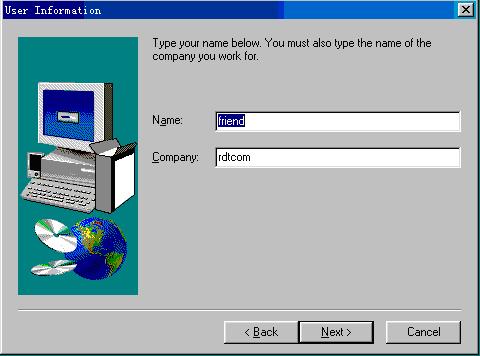
2.1 Double-click "Setup.exe" in the network management directory to enter the "Welcome" dialog box; click "Next" to enter the "User Information" dialog box, where you fill in your name and company name. As shown in Figure 4
@@IMG3@@
Figure 4
Step 3:
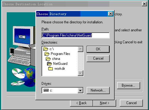
2.1 Click "Next" to enter the "Choose Destination Location" dialog box. You can click the "Browse" button to select the directory where the program will be installed (the default directory is "C:\Program Files\china\NetGuard"), as shown in Figure 5
@@IMG4@@
Figure 5
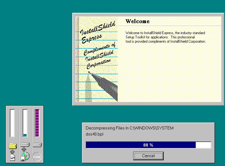
2.4 Step 4: After selecting the directory, click "Next" to enter the "Select Program Folder" dialog box (this may take a moment). It is recommended to use the default settings here. Click "Next" directly to enter the "Start Copying Files" dialog box; click "Next" to proceed with the installation (this will take some time), as shown in Figure 6.
@@IMG5@@
Figure 6
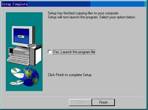
2.5 Step 5: After installation is complete, click the "Finish" button in the "Setup Complete" dialog box that appears. The installation is now fully complete. As shown in Figure 7.
@@IMG6@@
Figure 7
Note: During the installation process, you can click the "Back" button to return to the previous dialog box, or click "Cancel" and then click "Exit" in the "Exit Setup" dialog box to exit the installation program.
Chapter 3 Menus and Windows
3.1 Interface Introduction
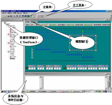
The main interface consists of five parts:
Main Menu
Main Toolbar
Resource Management Window
View Window
System Information and Event Log Window
@@IMG7@@
Figure 8
3.2 Menu Introduction
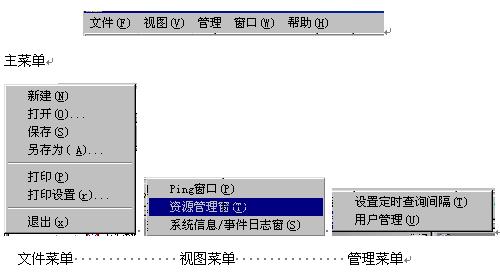
The main menu consists of File, View, Management, Window, and Help; the File menu consists of New, Open, Save, Save As, Print, Print Setup, and Exit; the View menu consists of Ping Window (currently unavailable), Resource Management Window, and System Information/Event Log Window; the Management menu consists of Set Query Interval (sets the automatic refresh time interval, in units of 10 seconds) and User Management (manages user permissions; super users can add or delete users, while other users do not have this permission).
@@IMG8@@
Figure 9
3.3 Main Toolbar Introduction
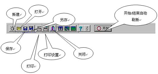
The main toolbar mainly consists of New, Open, Save, Save As, Print, Print Setup, Close, and Start/Stop Auto Refresh.
@@IMG9@@
Figure 10
Chapter 4 Usage Instructions
4.1 Login
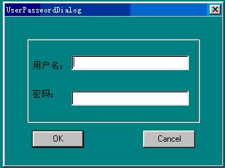
Start the NetGuard software in the directory where the program is installed (by default "C:\Program Files\china\NetGuard"). A user login window will appear, requesting the username and password (by default, the super user name is "admin" and the password is "admin"), as shown in Figure 11. If an incorrect user or password is entered, the program cannot be exited. You can select different operation permissions as needed during login (the following operations are all performed as super administrator).
@@IMG10@@
Figure 11
4.2 Creating an IDM120 Management Object
4.2.1 Setting Up the Network
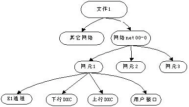
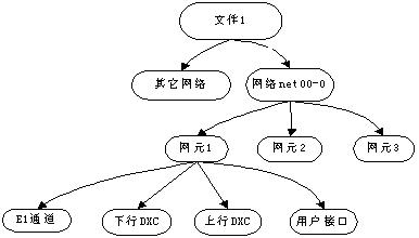
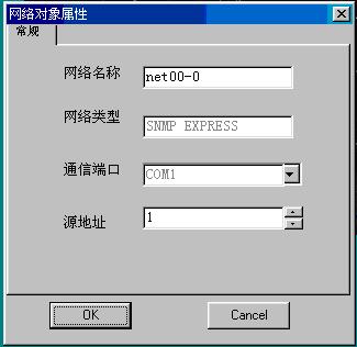
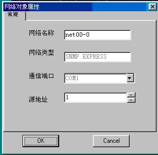
After successful login, enter the main management window and select "File 1" in the "Tree Form" dialog box. In the right-click menu, there is "Add Network" where you can add your own network (by default, the network "NET00-0" has already been created for you). Select "NET00-0", right-click, and click "Object Properties" in the pop-up menu. In the network object properties: select "SNMP Express" as the network type; select the COM port currently used by the PC for the communication port (e.g., COM1); the "Source Address" refers to the ADM120 host address connected to the PC, which can range from 0 to 32 (e.g., Station 1 connected to the PC). After configuration, click "OK".
@@IMG11@@
Figure 12
4.2.2 Setting Up Network Elements
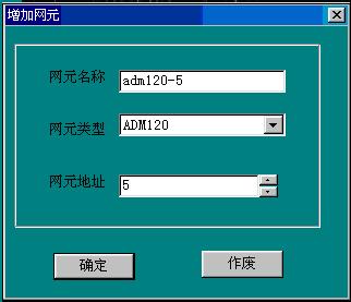
Add network elements according to the required network configuration (each device is a network element; by default, the "Object Properties" in the menu has already been configured).
@@IMG12@@
Figure 13
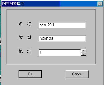
Select the network element "adm120-1" and set the network element object properties in the right-click menu's Object Properties. Here, only the address change takes effect; changes to the network element name and network element type are invalid.
The view window of the network element is shown in Figure 14 below:
4.3 Functional Description of Each Management Module
4.3.1 Host Device Status Query and Setting Function
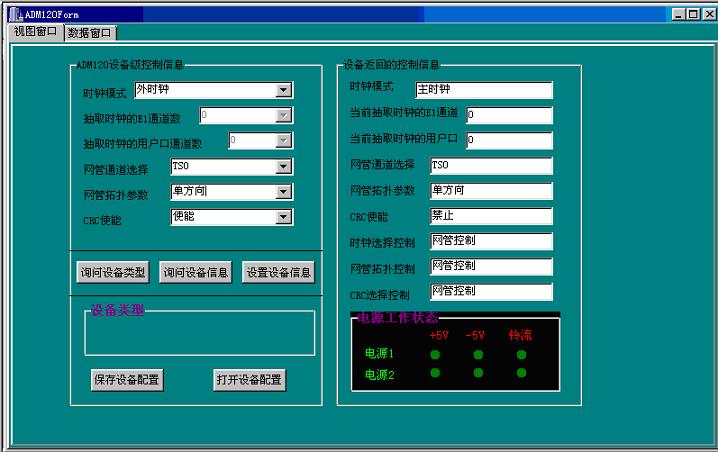
Directly select the host to be queried in the tree directory, as shown in Figure 14:
@@IMG13@@
Figure 14
Setting Introduction:
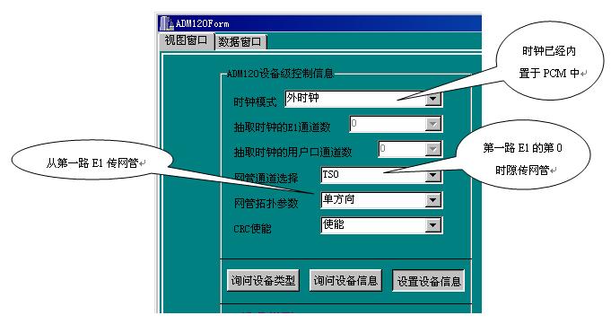
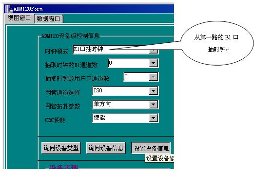
There are four clock modes: Master Clock, External Clock, E1 Port Extracted Clock, and Synchronous User Port Extracted Clock. For the ADM120, a high-precision clock source is already built into the unit, so the network element that the user wants to set as the master clock should be set to "External Clock", and there can only be one master clock in the entire network. Other network elements can only be set to E1 Port Extracted Clock or Synchronous User Port Extracted Clock. The synchronous user ports include V.35, V.24, and other data channels.
4.3.1.1 Network Management Channel Selection: You can select Timeslot 0 or Timeslot 1 of the E1 channel.
4.3.1.2 Network Management Topology Parameters have four options:
- Single Direction: uses only the first E1 channel for network management transmission;
- Dual Direction: uses the first and second E1 channels for network management transmission;
- Triple Direction: uses the first, second, and third E1 channels for network management transmission;
- Quad Direction: uses the first, second, third, and fourth E1 channels for network management transmission;
4.3.1.3 CRC Enable: CRC can be disabled or enabled via the network management system.
Important Notes:
The above settings do not apply to the "Economy Model IDM-120P".
The network topology parameters must match the actual number of E1 tributaries in use.
When the host is a slave station, it must be set from which E1 tributary the clock is extracted.
When the returned information matches the setting information, the settings have taken effect.
4.3.2 Four E1 Tributary Status Query and Setting Function
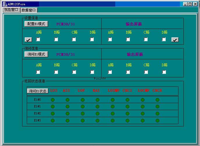
In the "TreeForm", select "E1 Channel" and the view window will display as shown in Figure 15.
@@IMG14@@
Figure 15
Configuration Introduction:
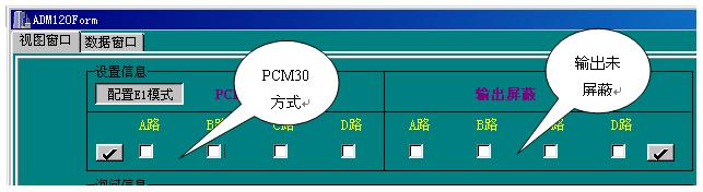
Configure the E1 mode by selecting any of channels A, B, C, or D (check the boxes), then click "Configure E1 Mode" to complete the configuration. The selected E1 channels use PCM31 mode, which does not transmit signaling (Timeslot 16); otherwise, signaling is transmitted in Timeslot 16.
The alarms of the four output E1 channels can be masked (by selecting and configuring).
Querying the E1 mode allows you to verify whether the above settings were successful. Once the returned information matches the configuration information, the configuration has taken effect.
The returned status information shows the alarm status of the E1 channels. A lit indicator indicates an alarm. The meanings of each alarm are as follows:
LOS: Indicates Loss of Signal alarm, '1' indicates an alarm.
AIS: Indicates Remote Alarm (i.e., all-ones alarm received on the line);
LOF: Indicates Loss of Frame;
RAL: Indicates Remote Alarm Indication A1;
LOSMF: Indicates Signaling Multiframe Loss alarm;
CRCI: Indicates CRC-4 Check Error alarm;
LOCMF: Indicates Multiframe Loss alarm;
4.3.3 Cross-Connect Matrix (DXC) Query and Setting Function
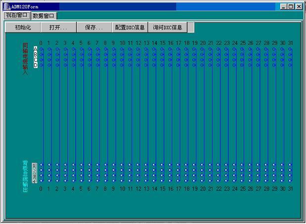
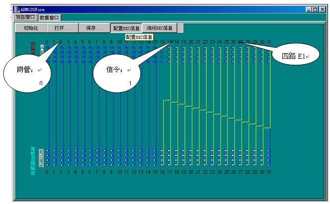
4.3.3.1 Double-click the downstream DXC. After the background color turns blue, the view window displays as shown in Figure 16.
@@IMG15@@
Figure 16
Initialize: Resets the entire view window to its initial state (Figure 16 is the initial state).
Open: Opens a previously saved configuration scheme (4 common configuration schemes are already available).
Save: Saves the configured scheme for future use.
Configure DXC Information: Configures the prepared cross-connect configuration to the device.
Query DXC Info: Allows querying the cross-connection status on the device to verify whether the configuration has taken effect.
Coaxial cable inputs A, B, C, D represent four E1 lines, each with 0-31 timeslot inputs.
Backplane bus outputs 1, 2, 3, 4 represent the four downstream DXC bus groups, each with 0-31 timeslot outputs.
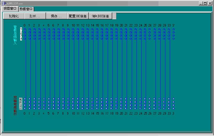
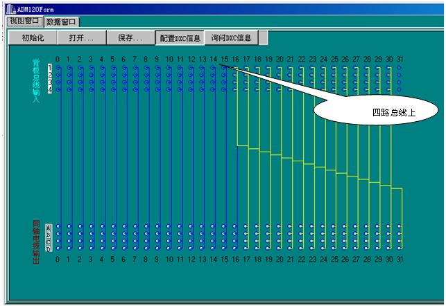
4.3.3.2 Double-click the upstream DXC; after the background color turns blue, the view window displays as shown in Figure 17.
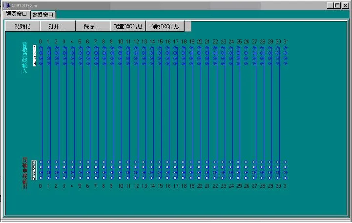
Figure 17
Initialization: Resets the entire view window to its initial state (Figure 6 shows the initial state).
Open: Opens a previously saved configuration scheme (4 common configuration schemes are available).
Save: Saves the configured scheme for future use.
Configure DXC Info: Configures the configured cross-connections to the device.
Query DXC Info: Allows querying the cross-connection status on the device to verify whether the configuration has taken effect.
The configuration method is the same as that for the downstream DXC.
Backplane bus inputs 1, 2, 3, 4 represent the four upstream DXC bus groups, each with 0-31 timeslot inputs.
Coaxial cable outputs A, B, C, D represent four E1 lines, each with 0-31 timeslot outputs.
4.3.4 Query and Configuration Functions for Backplane Bus and User Service Interfaces
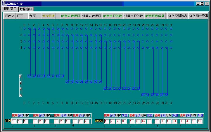
User service interface: after the background color turns blue, the view window displays as shown in Figure 18.
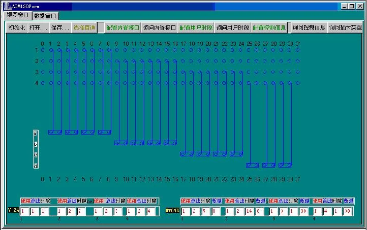
Figure 18
Initialization: Resets the entire view window to its initial state;
Open: Opens an existing configuration scheme (3 schemes have been configured);
Save: Saves the current scheme;
Select Bypass: The signal loops back directly without passing through the card (in bypass mode);
Configure Built-in Interface: Refers to configuring the V24 and N*64 interfaces;
Query Built-in Interface: Queries the configuration status of the built-in interfaces;
Configure User Timeslots: Configures the connections between the four groups of 0-31 timeslots on backplane buses 1, 2, 3, 4 of the downstream DXC and the slots;
Query User Timeslots: Queries the connections between the four groups of 0-31 timeslots on backplane buses 1, 2, 3, 4 of the downstream DXC and the slots;
Configure Control Info:
Query Control Info:
Query Card Type: Queries the type of card installed in the slot, including V24, audio card, central office card, remote card, etc.
Built-in Interface Configuration:
A usage value of 0 indicates the link is not used; 1 indicates it is in use;
The bus number corresponds to the four groups of backplane buses; the timeslot number is the actual starting timeslot;
Quantity: Corresponds to the bandwidth of the multi-timeslot card.
Note: Double-clicking the slot icon displays detailed information for each slot;
The four groups of 0-31 timeslots labeled 1, 2, 3, 4 represent the corresponding interfaces on the backplane bus (DXC).
A, B, C, D represent the timeslots corresponding to the 30 channels of 64K services from slots 1-15.
V24 represents the manual timeslot configuration items for the four V24 channels of the extended built-in interface.
N*64 represents the manual timeslot configuration items for the four V35 or 10BaseT channels of the extended built-in interface.
Chapter 5 Typical Configuration Examples
5.1 Four Voice Channels and One Network Channel Point-to-Point Interconnection
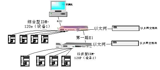
5.1.1 Let us examine an example of two economy-type devices interconnected, as shown in the connection diagram below:
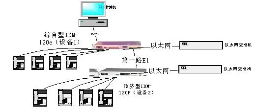
Figure 19
5.1.2 Now we set Device 1 as the master station (Station 1) and Device 2 as the slave station (Station 2), using Serial Port 1, with the network management cable connected to Station 1. The configuration is as follows, and the network management object properties are shown in Figure 20.
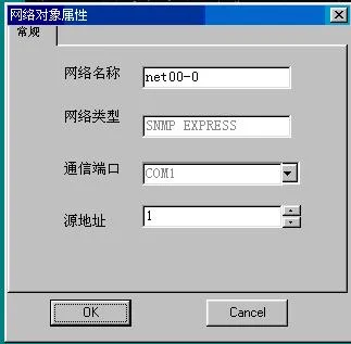
Figure 20
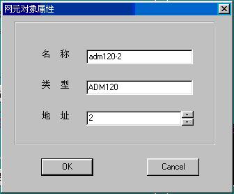
5.1.3 The network element object properties of the first network element (Device 1) are shown in Figure 21, and those of the second network element (Device 2) are shown in Figure 22.
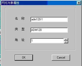
Figure 21
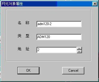
Figure 22
5.1.4
The view window settings of the first network element (Device 1) are shown in Figure 23, and the view window settings of the second network element (Device 2) are shown in Figure 24. However, since the second network element is an economy-type IDM, the settings of the second network element do not take effect; they are provided here for reference only in other scenarios.
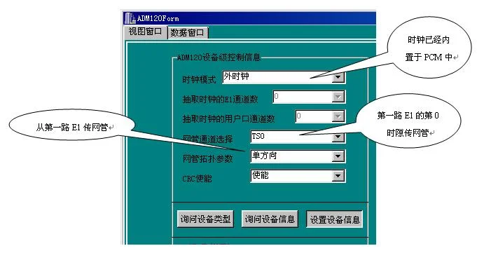
Figure 23
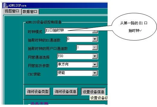
Figure 24
5.1.5
The E1 channel settings are shown in Figure 25. When transmitting signals with signaling such as voice, PCM30 mode should always be used. Unless under special circumstances, the output is generally not masked.
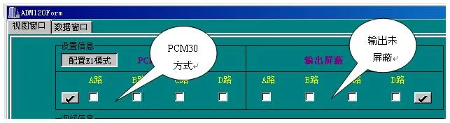
Figure 25
5.1.6 The downstream bus configuration is shown in Figure 26. The signal is input from the first channel of the coaxial cable, then split into one signaling signal (timeslot 16), one network management signal (timeslot 0), and 30 service signals. The 30 service signals are divided into four groups and sent to the four buses on the backplane, then to each card. The upstream bus is the reverse of this process, as shown in Figure 27.
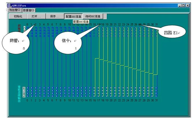
Figure 26
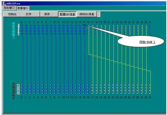
Figure 27
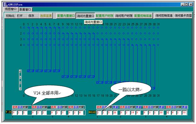
5.1.7 The user interface configuration is shown in Figure 28 below. The figure shows one Ethernet card and two telephone cards configured.
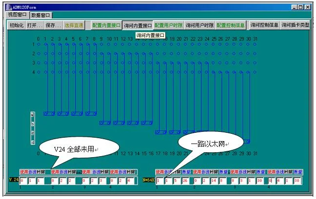
Figure 28
Note:
The telephone cards occupy the first four timeslots; the 26 timeslots after timeslot 5 are all used by Ethernet.
When the user interface configuration conflicts with the installed cards, a priority order applies: V24 > N*64K > card;
The timeslots allocated to N*64K must be consecutive timeslots;
User interface configuration must be performed on the basis of the upstream/downstream configuration.
The E1 channel, upstream DXC, downstream DXC, and user interface configurations of the two IDM devices are similar. As long as the cards correspond to each other, the configurations can be identical (not repeated here).
5.2 Four Voice Channels and One Network Channel: One Master Station with Four Slave Stations
Let us examine the example of four voice channels and one network channel with one master station and four slave stations. The connection (telephones for Devices 3-5 are not shown) is as follows. It is worth noting that all four slave stations should use the first 2M to extract the clock.
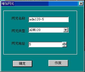
Now we set Device 1 as the master station (Station 1) and the other devices as slave stations, using Serial Port 1, with the network management cable connected to Station 1. The configuration is as follows, and the network management object properties are shown in Figure 21. Now, on the default basis (four network elements), add one more network element, as shown in Figure 30.
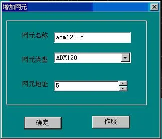
Figure 30
The network element object properties of the first network element (Device 1) are shown in Figure 21, those of the second network element (Device 2) are shown in Figure 22, and the third through fifth network elements are similar to the second.
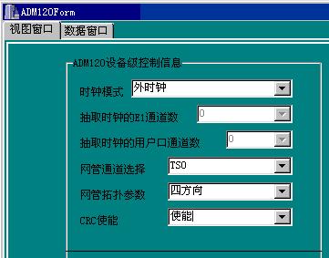
The settings in the view window of the first network element (Device 1) are shown in Figure 31 (if it is not an economy-type product), and the view window settings of the second network element (Device 2) are shown in Figure 24. The third through fifth network elements are similar to the second. Note that for the economy-type PCM120, all settings here are invalid.
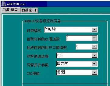
Figure 31
The E1 channel settings for each network element are shown in Figure 25. When transmitting signals with signaling such as voice, PCM30 mode should always be used, and the output is generally not masked unless under special circumstances.
The downstream bus configuration for each network element is shown in Figure 26. The signals are input from the four coaxial cables respectively, sent to the four buses on the backplane, and then to each card. The upstream bus is the reverse of this process, as shown in Figure 27.
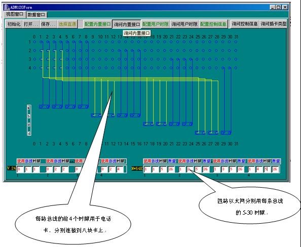
The user interface configuration of Device 1 is shown in Figure 32 below. The figure shows four Ethernet cards and eight telephone cards configured.
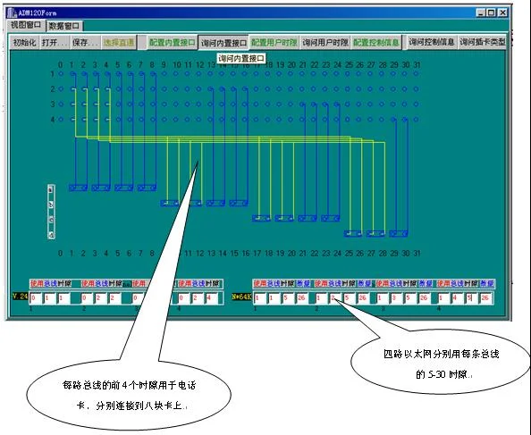
Figure 32
The user interface configuration of Devices 2 through 5 is shown in Figure 28. Refer to the relevant settings in the four-voice-one-network point-to-point interconnection example. The figure shows one Ethernet channel and two telephone channels configured. At this point, the configuration of four voice channels and one network channel with one master station and four slave stations is complete.