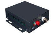
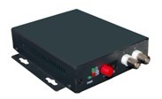
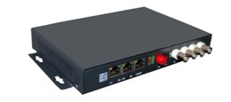
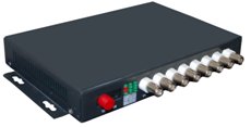
IDM VHD6000
IDM VHD6000
The IDM VHD6000/16H Series Audio/Video Optical Transceiver supports real-time, synchronized, and lossless transmission of high-definition and ultra-high-definition high-quality images. Due to the adoption of digital fiber optic transmission technology, the transmission distance for high-definition images is longer, with strong anti-interference capability and larger transmission scale. This series is divided into two categories: the HD series supports 1080P@60Hz and provides interconnectivity among HDMI, DVI, VGA, and SDI interfaces. The IDM VHD6000/16H Series Audio/Video Optical Transceiver supports transmission of 16 channels of HDMI high-definition video and 16 channels of audio, while also supporting simultaneous transmission of various data such as data, Ethernet, IO, IR, USB, telephone, and E1. This series adopts JPEG2000 compression technology.
I. Product Overview
The IDM VHD6000/16H Series Audio/Video Optical Terminal employs JPEG2000 lossless compression technology and supports real-time synchronous, lossless transmission of HD and Ultra HD high-quality images. Thanks to digital fiber optic transmission technology, HD image transmission distance is extended, anti-interference capability is enhanced, and transmission scale is larger. This series is divided into two categories: the HD series supports 1080P@60Hz and provides interconnectivity among HDMI, DVI, VGA, and SDI interfaces.
The IDM VHD6000/16H Series Audio/Video Optical Terminal supports 16 channels of HDMI HD video and 16 channels of audio transmission, while also supporting simultaneous transmission of multiple data types such as data, Ethernet, IO, IR, USB, telephone, and E1. Due to the adoption of JPEG2000 compression technology, this series enables point-to-point, point-to-multipoint, multipoint-to-multipoint, and one-transmit-multiple-receive transmission modes, and is widely used in multimedia video conferencing, teaching recording and broadcasting, multimedia exhibition halls, advertising media, multi-screen interaction, and many other fields.
II. Product Applications
Multimedia Video Conference | Multimedia Teaching Recording & Broadcasting |
Medical Teaching Demonstration | Command Center |
Public Security & Transportation | Financial & Banking Systems |
Advertising Media | Broadcast & Television |
Military Communication | Security & Surveillance Systems |
III. Product Features
n Multiple interface interconnectivity: Supports HDMI, DVI, VGA, SDI interconnectivity;
n Supports 16 channels of HDMI HD video signals transmitted simultaneously in the same direction;
n Supports 16 channels of audio transmission;
n Multiple resolution support: Supports up to 1920×1080@60Hz and various lower resolutions;
n Multiple service interface support: Supports various service interfaces in addition to HD video, including balanced and unbalanced audio, control data, dry contacts, IR, USB, telephone, E1, Ethernet, etc.
n Optical module is single-mode single-fiber, supporting a default transmission distance of 40KM, with optional maximum fiber transmission distance of 120KM;
n Automatically identifies and configures various display modes;
n Supports 16-bit color depth video signals, with transmission bandwidth up to 10Gbps;
n Maximum pixel clock of 225MHz;
n Built-in automatic equalization and retiming functions for clear and stable images;
n Adopts V-EDID technology, with transmitter supporting EDID self-programming;
n Supports HDCP protocol and DDC2B protocol;
n Video, data, and power interfaces designed with lightning and ESD protection;
n Power interface designed with reverse polarity protection, surge protection, and high-voltage protection;
n Compact and lightweight structure, easy installation, plug-and-play;
n Available in wall-mounted and rack-mounted configurations.
IV. Physical Parameters
Power Supply | Wall-mounted: DC 5V/1A~1.5A Rack-mounted: AC220V or / and DC48V |
Power Consumption | Wall-mounted: <10W Rack-mounted: Depends on specific configuration |
MTBF | Greater than 100,000 hours |
Operating Temperature | -20°C~+75°C |
Storage Temperature | -40°C~+85°C |
Relative Humidity | 0~95 % |
Dimensions | 16-channel: 440x165x180mm, 4U, 19-inch standard chassis |
Free from corrosive and solvent gases, dust-free, and no strong magnetic field interference. | |
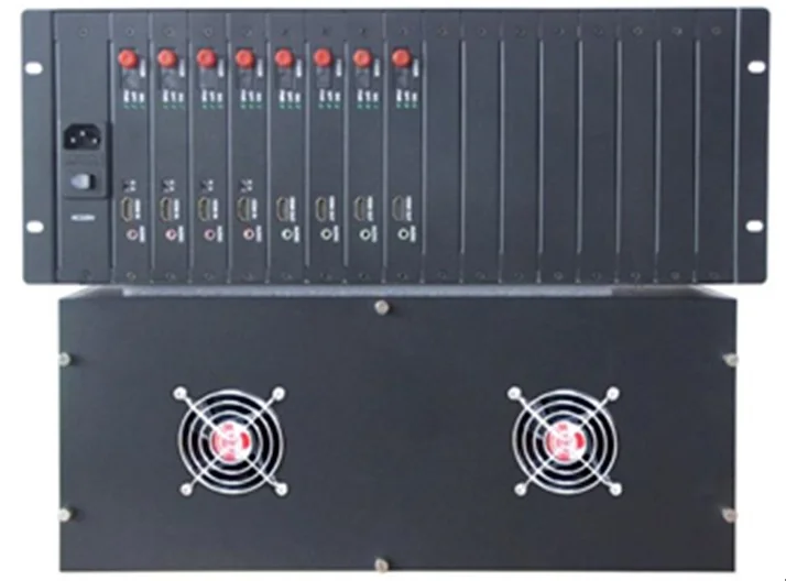
5. Equipment Structure and Images
6. Technical Parameters
6.1 Optical Interface
Interface | FC (default), SC, ST optional |
Rate | 1.25Gbps (1 channel) 2.5Gbps (2~8 channels) CWDM (16~64 channels) |
Transmission Distance | 20Km (default); special distances to be specified in advance |
Wavelength | Multimode: 850nm/1310nm Singlemode: 1310nm/1550nm |
Applicable Fiber Type | Multimode: 50μm/125μm, 62.5μm/125μm Singlemode: 9μm /125μm |
6.2 Video Interface
HDMIInterface | |
Video Input: | TMDS signal; |
Physical Interface: | HDMI1.3bType-afemale connector; |
Maximum Video Pixel Clock: | 225M; |
Video Color Depth: | 8/10/12bit; |
E-DDC Standard: | E-DDC2/EDID; |
E-DDC: | 5VTTL level. |
DVIInterface | |
Video Input: | DVI 1.0;HDCP 1.2; |
Physical Interface: | DVIInterface1x18+1 DVI-Dmale connector; |
Maximum Video Pixel Clock: | 225M; |
Video Color Depth: | 8/10/12bit; |
E-DDC Standard: | E-DDC2/EDID; |
E-DDC: | 5VTTL level; |
VGAInterface | |
VGA InterfaceStandard: | DB15/Ffemale connector; |
Resolution: | VGA640x480@60HZ~WUXGA1920x1080@60Hz |
Input Video Analog Bandwidth: | 500MHz(3dB); |
Input Video Level: | 0.7Vp-p, typical,max1.5Vp-p; |
Input Video Impedance: | 75Ω; |
Input Coupling: | DC; |
Horizontal Sync Frequency: | 15KHz~200KHz; |
Vertical Sync Frequency: | 30Hz~200Hz; |
H/V Sync Input Impedance: | 510Ω; |
SDIInterface | |
Signal Standard: | SMPTE424M,SMPTE292M,SMPTE259M,DVB-ASI; |
Data Rate: | 270Mbit/s-1.48Gbit/s–2.97Gbit/s; |
Cable Equalization: | 250m@270Mbit/s,140m@1.5Gbit/s,80m@2.97Gbit/s; |
Signal Amplitude: | 800mV±10%; |
SupportedResolution: | 1080p60HZ/50HZ;1080P30HZ/25HZ; 1080I60HZ/50HZ;720P60HZ/50HZ;576i;480i |
Physical Interface: | BNC connector, 75Ω; |
CVBSInterface | |
Video Format: | PAL/NTSC; |
Input Level: | 0.5-2Vpp; |
Output Level: | 1Vp-pBandwidth(-3dB)8MHz; |
Digital Bit Width: | 12bit; |
Differential Gain: | ≤1%; |
Differential Phase: | ≤1°; |
Weighted Signal-to-Noise Ratio: | ≥75dB; |
Connector: | BNC75Ω. |
Note
u The device is labeled with TX and RX tags: TX indicates the transmitter, and RX indicates the receiver.
u The bottom label shows the device configuration; please refer to it for details.
Data interface pin assignment:
Default: RS-485 Optional: RS-232, RS-422, TTL, dry contact | Direction |
Forward, reverse, or bidirectional (selectable) | Transmission Rate |
115200bps | Operating Mode |
Half-duplex/full-duplex | Interface |
3.81mm standard Phoenix industrial terminal | Data Format |
Note
Default: RS-485 Optional: RS-232, RS-422, TTL, dry contact | Direction | ||
Forward, reverse, or bidirectional (selectable) | Transmission Rate | 115200bps | |
Operating Mode | Half-duplex/full-duplex | Pin | |
3.81mmStandard Phoenix Industrial Terminal | RS-485 | RS-422 | |
RS-232 | Ch1RS-485+ | RS-422RX+ | |
Ch1RS-232 TX | Ch1RS-485- | RS-422RX- | Ch1RS-232 RX |
GND | GND | GND | 4 |
u RS-485 data interfaces can be cascaded. When multiple RS-485 devices need to be connected (e.g., multiple PTZ cameras), the RS-485+ terminals of all RS-485 devices can be tied together with the RS-485+ terminal of the optical transceiver, and the RS-485- terminals likewise tied together. The RS-485 devices will operate normally if they are equipped with a decoder board (PTZ cameras generally include one).
u When only one data channel is used, the first data interface should be used first, and the other pins should be left floating.
6.4 Audio Interface
Audio interface pinout definitions:
Ch2RS-485+ | |
RS-422TX+ | Ch2RS-232 TX |
5 | Ch2RS-485- |
RS-422TX- | Ch2RS-232 RX |
Unbalanced Audio Interface | Interface |
3.81mm standard Phoenix industrial terminal | Direction |
Forward, reverse, or bidirectional (selectable) | Bandwidth |
20Hz~20KHz | Quantization |
24bit | |
6.5 Digital I/O Interface (Optional)
Impedance | Line-in:47Ω(unbalanced) Line-out:10Ω(unbalanced) |
Signal-to-Noise Ratio | 85dB(unbalanced weighted typical) |
Total Harmonic Distortion | 0.1%(typical) |
The audio interface and data interface share a single5-pin industrial terminal for connection. | Pin |
Pin Definition (5-position industrial terminal block) | 1 |
LIN: Left channel audio input | 2 |
RIN: Right channel audio input | |
3 | GND |
4 | LOUT: Left channel audio output |
5 | ROUT: Right channel audio output |
Balanced Audio Interface | Connector: |
XLR or RCA connector, both optional; | Input/output level: |
2Vp-p; | Total harmonic distortion: |
≤1%; | Bandwidth (-3dB): |
6.6 USB Interface (Optional)
20~20KHz; | Audio encoding: |
24bit | Input/output impedance: |
600Ω or 100KΩ; | Weighted signal-to-noise ratio: |
≥80dB; | Physical Interface: |
Terminal block | Input/Output Mode: |
Input mode selectable asTTL input or dry contact input | Dry Contact Input: |
Short circuit or open circuit | Output Mode: |
6.7 Ethernet Interface (Optional)
Selectable as5VTTL/24VTTL output, or relay output | Relay Output FormFORMC(SPDT: |
Relay operate time6ms Relay release time3ms Total switching time10ms Relay contact rating1A/24VDC | Transmission delay: |
2ms | |
Maximum operating switching frequency: | 50Hz |
Interface Standard: | USB2.0/USB1.1 |
Physical Interface: | |
Upstream Port:USB type B |
Pin definition of the Ethernet crossover RJ45 interface:
Downstream Port:USB type A | Number of Ports: |
As specified or per customer requirements | Communication Rate: |
| Full speed: 12 Mbps | High Speed:480Mbps |
Full Speed:12 Mbps | Low Speed:1.5 Mbps |
Pin assignment of the Ethernet RJ45 interface:
Interface | RJ45 (with LEDs) | Bandwidth | 100M maximum | Auto-negotiation | Supports10/100M, full-duplex/half-duplex auto-negotiation | Auto MDI/MDIX | Supported, automatically detects straight-through/crossover cables | Pin |
1 | 2 | 3 | 4 | 5 |
6.8 Power Supply
6 | 7 |
8 | Pin Definition |
FAQs
What Are the Functions and Advantages of Video Optical Terminals?
The function of a video optical terminal is to convert one or multiple channels of analog video signals into optical…
View answerWhat is the difference between a Video Optical Terminal and a Network Video Server?
Composition and Function of Video Optical Terminal and Network Video Server An optical terminal is a device used to…
View answerWhat are common issues when using optical terminals in security surveillance?
Fiber optic technology is increasingly used in security surveillance projects to transmit images, audio, data…
View answer