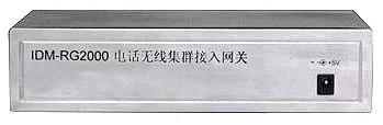
IDM-RG2000 Telephone Wireless Trunking Access Gateway
This device enables communication between radios operating on two different frequency bands, providing conversion functionality from ordinary telephones to two radio audio interfaces. It supports three operating modes: one-to-one direct mode from telephone to radio, conference mode from the first channel to two radios, and conference mode from the second radio to two radios. The ordinary telephone interface can interface with mainstream telephone exchanges in China.
Gallery
Overview
This device enables communication between radios operating on two different frequency bands, supporting conversion functionality from two IP telephone/ordinary telephone lines to two radio audio interfaces. It supports three operating modes: one-to-one direct mode from telephone to radio, conference mode from the first channel to two radios, and conference mode from the second radio to two radios. The ordinary telephone interface can interface with mainstream telephone exchanges in China. The IDM_RG2000 series devices are mainly available in two versions, as follows:
Model | Number of Radio Channels | Ethernet Interface | Description |
IDM-RG2000 | 2 | None | Provides two POTS lines and two radio interfaces |
Structure Description
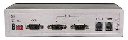
IDM_RG2000 Device Panel:
Figure 2.1 IDM_RG2000 Device Front Panel Diagram
Figure 2.2 IDM_RG2000 Device Rear Panel Diagram
Panel Interfaces
Power interface, indicator LEDs, and DIP switches. (Two power input options: 220V AC and +5V DC)
² Management interface: CON DB9 interface
² Radio interface: DB9 interface
² Trunk interface: RJ11 interface
² LAN interfaces: LAN1~LAN4
² WAN interface: WAN
The LED indicators on the device panel provide device status and alarm information, allowing users to easily determine whether the device is operating normally or in an alarm state. The panel indicator definitions are as follows:
Table 2.1.1 IDM_RG2000 Indicator Descriptions
Name | Color | Function | Description |
PWR | Green | Power supply status | This LED is on when the system power supply is normal; it is off when the power supply is abnormal. |
ACT | Green | Device operation indicator | When the device CPU is operating normally, this LED blinks on and off at 250 ms intervals; when abnormal, it remains steadily on or off. |
LED1 | Green | Channel audio indicator | This LED is on when there is audio on the telephone channel; it is off when there is no audio. |
LED2 | Green | Channel audio indicator | This LED is on when there is audio on the radio channel; it is off when there is no audio. |
The DIP switch controls the device operating mode, allowing users to configure it according to the application scenario. The DIP switch usage is shown in the table below:
Table 2.1.2 IDM_RG2000 DIP Switch Usage Instructions
SW | 1 | 2 | 3 | 4 |
ON | Mode select low bit | Mode select | Mode select | Mode select high bit |
OFF |
SW_4 SW_3 SW-2 SW_1: Device operating mode selection description:
0 0 0 0 : The device operates in telephone-radio one-to-one direct pass-through mode;
0 0 0 1 : The device operates in conference mode between the first telephone channel and the first and second radio channels;
0 0 1 0 : The device operates in conference mode between the second telephone channel and the first and second radio channels;
Physical Dimensions
- IDM_RG2000 Version:
The standard version adopts a desktop form factor with the following specifications:
120 × 190 × 44 (mm)
Interface Characteristics
The service interfaces provided by the IDM-RG2000 telephone gateway include: radio audio interfaces, FXO telephone interfaces, and Ethernet interfaces. The interface characteristics are as follows:
Radio Audio Interface Characteristics
² The device provides: 2 radio audio interfaces
² The audio interfaces use transformer coupling for strong anti-interference capability.
² Audio input/output impedance: 600Ω.
² The receive and transmit gain of the audio interfaces is adjustable, with a default of: 0dB transmit, 0dB receive.
² The audio interface is balanced input, and can also be connected as unbalanced (one end grounded), with an input impedance of 600Ω.
Telephone Trunk Interface Characteristics
² The device provides: 2 FXO trunk telephone interfaces;
² The telephone trunk interfaces use transformer coupling for strong anti-interference capability.
² The interface impedance is 200Ω+680Ω//0.1u three-element impedance (600Ω pure resistance can be provided upon user request).
Ethernet Electrical Interface
² 10/100BASE-T, full duplex, half duplex, auto-negotiation
² Standards compliance: IEEE 802.3, 802.1P, 802.1Q
² Connector: RJ45 (100M Cat5 twisted pair cable)
Ethernet Optical Interface
² 10/100BASE-FX
² Standards compliance: IEEE 802.3, 802.1P, 802.1Q
² Connector: FS
² Transmit power ≥ -5dBm, sensitivity ≤ -35dBm
² Wavelength: 1310/1550nm, transmission distance: 10km, 40km, up to 120km
Control Interface
² Asynchronous interface: 8 data bits, 1 stop bit, no parity
² Baud rate: 57600
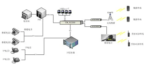
Typical Application