IDM OMP64 Integrated Service Optical Fiber Transmission Equipment
Dual Gigabit Physically Isolated 64-Channel Telephone Single-Fiber 2.5G Saves One Optical Multiplexer
The IDM OMP64 physically isolated gigabit network optical multiplexer has a total optical fiber transmission bandwidth of 2.5G and provides 2 independent 1000M Ethernet interfaces and 64 telephone subscriber channels; meanwhile, the IDM OMP64 physically isolated gigabit network optical multiplexer is simple to install and can meet the requirements of various application environments.
The IDM OMP64 integrated service optical fiber transmission equipment is a 64-channel telephone dual-gigabit optical multiplexer, developed by Beijing Ruiguang Jiyuan. It is a representative PDH product showcase model for private network scenarios, used to simultaneously transmit telephone voice and two independent gigabit Ethernet services over a single optical fiber. The unit provides a total optical fiber transmission bandwidth of 2.5G, 2 independent 1000M Ethernet interfaces, and 64 telephone subscriber channels; the E1 transmission channel complies with the G.703 standard and adopts the PCM30/31 format. As an integrated service access device, it combines the attributes of both PCM equipment and optical transmission equipment, and achieves physically isolated transmission of voice and data at the optical multiplexing equipment level.
For private network projects in electric power, rail transit, military and government sectors, the IDM OMP64 consolidates voice and data into a single unit. The site side no longer needs separate telephone optical multiplexers and Ethernet optical multiplexers; cabinet space, supporting power supply and optical cable resources are each occupied only once, and installation requires only a pair of SFP (small form-factor pluggable) modules. For government private network optical fiber communication solutions and military emergency communications vehicle solutions, the device effectively simplifies site provisioning and improves deployment efficiency, and also demonstrates the product showcase capability of a professional optical multiplexer manufacturer in the field of optical multiplexing equipment.
Key Specifications at a Glance: 2.5G optical fiber bandwidth · 2 independent gigabit Ethernet channels · 64 telephone voice channels · receiver sensitivity better than -36dBm · DC-48V/AC220V dual power supply · 19-inch 2U chassis
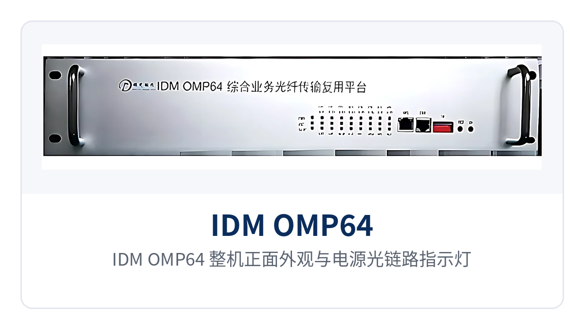
Figure 1: IDM OMP64 front view with power and optical link indicator LEDs
What kind of device is the IDM OMP64?
The IDM OMP64 is a PCM equipment for private network access scenarios, housed in a 19-inch 2U standard chassis. The front panel provides a function control switch and alarm indication, while the rear panel concentrates the optical interfaces, Ethernet interfaces and voice channel interfaces, allowing direct installation in a standard cabinet. As an integrated service access device, its optical side uses SFP interfaces with single-mode fiber transmission and optional multi-mode; the Ethernet side uses RJ-45 interfaces at 10/100/1000Base-T, with an operating mode of full/half duplex adaptive.
Physical isolation means the two gigabit Ethernet channels are each independent within the device, sharing neither bandwidth nor forwarding resources, and packets are never forwarded across channels. This design differs from VLAN partitioning: isolation is implemented at the hardware layer, so when one channel connects to the office network and the other carries production or monitoring data, the boundary is clear, and traffic fluctuations on either channel will not encroach on the other.
How does the 64-channel telephone dual-gigabit optical multiplexer achieve service isolation?
The total bandwidth of single-fiber 2.5G optical fiber transmission leaves margin for 2 gigabit Ethernet channels and 64 telephone channels to operate simultaneously. The two gigabit Ethernet channels are allocated independently at wire-speed, and the telephone voice channels are carried in fixed time slots per the PCM30/31 format; voice and data are transmitted in parallel over the same optical fiber, achieving physically isolated transmission of voice and data.
For private network projects, the value of isolated service transmission lies in clear boundaries of responsibility. Telephone voice travels over independent time slot channels, while monitoring or dispatch data travels over gigabit channels; when a service anomaly occurs, the troubleshooting scope narrows to a single channel, with no need to guess segment by segment across a shared link. The unit delivers three capabilities over one optical fiber at once—2.5G optical fiber bandwidth, 64 telephone channels and dual gigabit Ethernet—so a single 64-channel telephone dual-gigabit optical multiplexer covers voice and data access on the site side.
Key Specifications and Interface Capabilities
The functions and interface capabilities of the IDM OMP64 are grouped into four categories—optical transmission, Ethernet, voice and power supply—and listed item by item in the table below. The parameters are taken from the product technical specifications and can be checked line by line during on-site configuration verification; specifications beyond this table are subject to the manufacturer's technical documentation.
| Function | Description |
|---|---|
| 64-channel telephone access | Provides 64 telephone subscriber channels with FXO and FXS interfaces, supporting polarity reversal and caller ID (CID) |
| 2 gigabit Ethernet channels | Provides 2 independent 1000M Ethernet interfaces; the two channels are physically isolated and do not share bandwidth |
| Single-fiber 2.5G transmission | Total optical fiber transmission bandwidth of 2.5G; voice and data are carried in parallel over the same optical fiber |
| PCM30/31 format | Telephone services are multiplexed into the transmission channel per the PCM30/31 format, and the channel complies with the G.703 standard |
| Alarm indication | The panel provides a function control switch and alarm indication for on-site assessment of link and service status |
| Dual power supply | DC-48V and AC220V power supply modes are selectable, adapting to different power distribution conditions in equipment rooms and sites |
The parameters of the optical interfaces and Ethernet interfaces are listed item by item in the table below. Transmit optical power and receiver sensitivity follow the factory optical module ratings; for link calculations, actual measured values on site shall prevail. For module types outside the rated range, confirm optical power and wavelength with the manufacturer before incorporating them into the link budget.
| Item | Parameter/Specification | Description/Applicable Conditions |
|---|---|---|
| Interface type (optical) | SFP | Single-mode, multi-mode optional |
| Optical fiber rate | 2.5G | Total optical fiber transmission bandwidth of the unit |
| Wavelength | 1310nm | Used in pairs with the optical module at the opposite end |
| Transmit optical power | -2 to -11dBm | Rated range of the factory optical module |
| Receiver sensitivity | Better than -36dBm | Determines the available margin of a weak optical link |
| Interface type (Ethernet) | RJ-45 | 10/100/1000Base-T |
| Transmission rate | 10M/100M/1000M | Full/half duplex/adaptive |
| Standard protocol | Supports IEEE802.3 | Interoperable with conventional switches and routers |
The voice interfaces, together with the unit's power supply and environmental parameters, are listed in the table below for confirmation during ordering and equipment room conditions verification. Voice channel impedance and compression determine matching with existing telephones and switches, while the power supply mode and power consumption determine the advance preparation for equipment room power distribution and cabinet heat dissipation.
| Item | Parameter/Specification | Description/Applicable Conditions |
|---|---|---|
| Audio range | 300Hz~3400Hz | Telephone voice bandwidth |
| Impedance | Three-element complex impedance 200Ω+560Ω//0.1μF | Voice channel interface matching |
| Compression | ITU G.711 A-law | Voice codec |
| Loop current | 25mA/channel | Voice channel power feeding current |
| Power supply mode | DC-48V or AC 220V | One of the two modes selected on site |
| Overall power consumption | ≤250W | Upper limit at full configuration |
| Operating temperature | 0℃~+40℃ | Equipment room or attended site |
| Relative humidity | 95% non-condensing | For use in non-condensing environments |
Can a weak optical long-distance link still receive stably?
Receiver sensitivity better than -36dBm means the link can still make correct decisions as long as attenuation stays within this threshold; long links with many splice points will not suffer frequent bit errors due to insufficient margin. Based on the lower transmit optical power limit of -11dBm and this sensitivity threshold, the link can tolerate approximately 25dB of attenuation, and splice point and fiber adapter losses must be included in this budget.
When troubleshooting weak optical signals on site, first read the measured optical power at the receiving end, then compare it segment by segment against the link budget. If the receiving-end reading approaches -30dBm, clean the fiber adapter end face, check the patch cord bend radius, and if necessary replace the optical module with a higher transmit optical power; keep 3~6dB of margin so the link can withstand temperature changes and connector aging, benefiting both voice and data services.
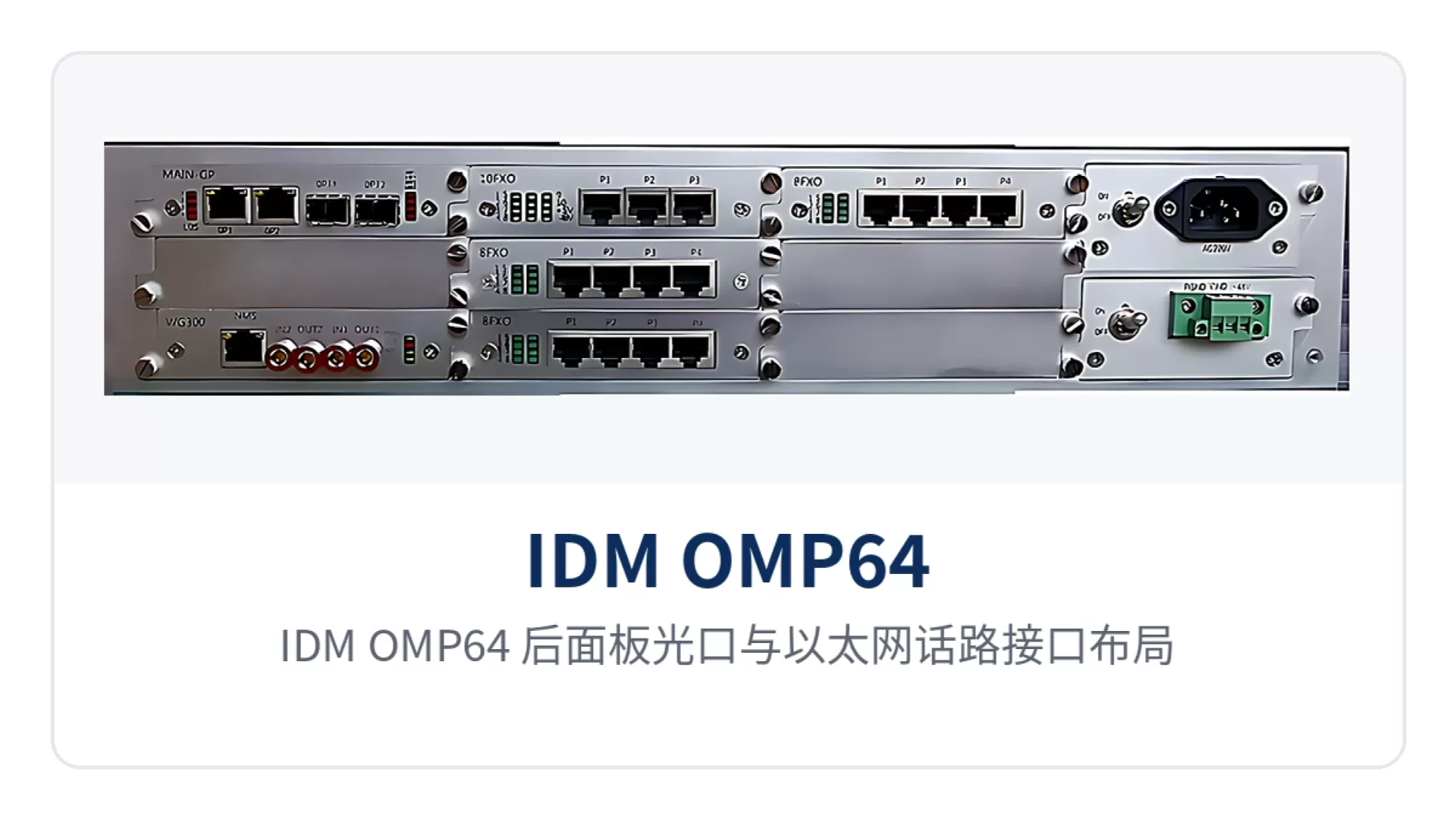
Figure 2: IDM OMP64 rear panel layout of optical ports and Ethernet/voice channel interfaces
How to choose between DC-48V and AC220V dual power supply?
The IDM OMP64 offers two power supply modes, DC-48V and AC220V: connect -48V when the equipment room has a DC distribution panel, or 220V when the site only has mains power, selecting one at ordering according to on-site power distribution conditions. The overall power consumption is ≤250W; calculate the power distribution capacity based on full-configuration services and reserve some margin for the power supply unit.
The chassis is 19-inch 2U; leave bending space for patch cords and power cables at the front and rear inside the cabinet, and keep ventilation unobstructed. Route voice cables and network cables on separate sides and do not bundle them together, so that during maintenance the service assignment can be determined from the port labels, and crosstalk from voice cables to data links is reduced.
Typical Application Scenarios
Electric power private network: telephone and data channels between substations and the dispatch center
Often only one optical fiber is available between a substation and the dispatch center, yet duty telephones, telecontrol data and video surveillance in the substation need to be backhauled simultaneously. As optical transmission equipment, the IDM OMP64 provides 2 gigabit Ethernet channels and 64 telephone channels over one optical fiber; telephones connect to on-site telephones and the dispatch console, and the two gigabit channels carry telecontrol and video respectively, with no crosstalk between services.
Electric power equipment rooms are generally equipped with -48V DC communications power supplies; drawing DC power directly keeps consistency with the existing power system in the substation. The IDM OMP64 operates from 0℃ to +40℃, so no additional temperature control equipment is needed when installed in an attended communications equipment room.
Rail transit communication: station duty telephones and monitoring data backhauled over the same fiber
Distances between stations and section equipment rooms are long and there are many mating connectors, making link attenuation a common issue. Receiver sensitivity better than -36dBm leaves optical power margin for long-distance links, so duty telephone connection and voice quality remain guaranteed under weak optical conditions, and monitoring image backhaul is less prone to interruption.
Rail transit telephone services are mostly inter-station pass-through; FXO and FXS are paired according to the interface types of the telephones and switches at both ends—one side connects to the central office and the other to the telephone for direct calls. The 64-channel capacity covers telephone requirements for job roles such as station duty, platform, ticketing and equipment rooms, with no need to lay an additional optical fiber for telephones.
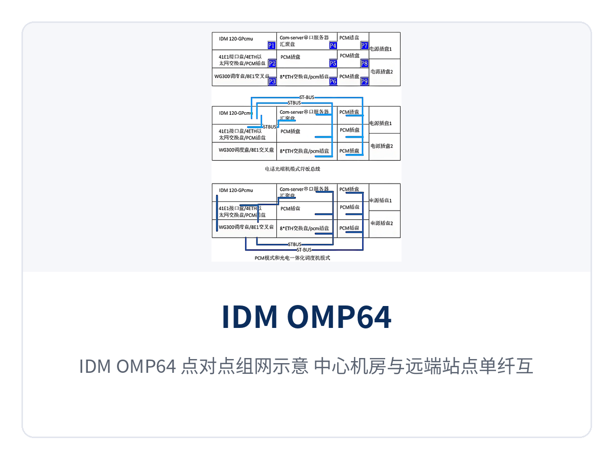
Figure 3: IDM OMP64 point-to-point networking diagram, single-fiber interconnection between central equipment room and remote station
Military and government private networks: voice and intranet data carried in separate domains
Private networks demand more of service boundaries than of bandwidth itself. The 2 gigabit Ethernet channels are physically isolated within the device and can connect to the office network and the service network respectively; voice travels over independent PCM time slot channels, and the three service types each follow their own path over the same optical fiber, with cross-domain access blocked at the device side. Such optical multiplexing equipment is also often incorporated into the product showcase lists of government private network optical fiber communication solutions and military emergency communications vehicle solutions, as an option for unified voice and data access on the site side.
Government and military sites are mostly dispersed, with tight cabinet space. One 2U device handles both telephone access and two uplinks, saving cabinet space and supporting power supply; DC-48V power can be drawn directly from the existing power supply in the communications equipment room, reducing the engineering work of site modification. For optical multiplexer manufacturers, vendors such as Raytrans with a complete product line of PDH and PCM equipment can provide selection support for both optical transmission equipment and integrated service access devices at the solution stage.
How to install and commission on site?
On-site installation and commissioning proceed in six steps, each completed and verified before moving to the next. Optical paths and voice channels are two different types of interfaces; before wiring, label patch cords and voice cables separately so that subsequent troubleshooting can locate faults by label and voice cables are not mistakenly plugged into Ethernet ports. As a typical integrated service access device in the PDH product showcase, the IDM OMP64 is commissioned on site following these same six steps.
- Optical modules and patch cords: select SFP modules according to the wavelength and distance of the optical module at the opposite end, connect the receive and transmit fibers separately, and clean the end faces with anhydrous alcohol before insertion.
- Telephone interface wiring: assign FXO and FXS according to the interface types of telephones and switches, label each channel on the patch panel to avoid misalignment.
- Ethernet wiring: connect the two gigabit channels to the switches of the corresponding security domains respectively, and observe the port indicator LEDs and link status after plugging in.
- Power supply connection: connect DC-48V or AC220V according to the ordered mode, confirm polarity before switching on, and check the power indicator LED after switching on.
- Alarm verification: verify the panel alarms item by item, and confirm that the optical path, voice channels and Ethernet channels are in normal status before proceeding to commissioning.
- Service commissioning: dial-test the 64 voice channels in sections, run traffic tests on the two gigabit channels, and record the measured optical power and bit error conditions for archiving.
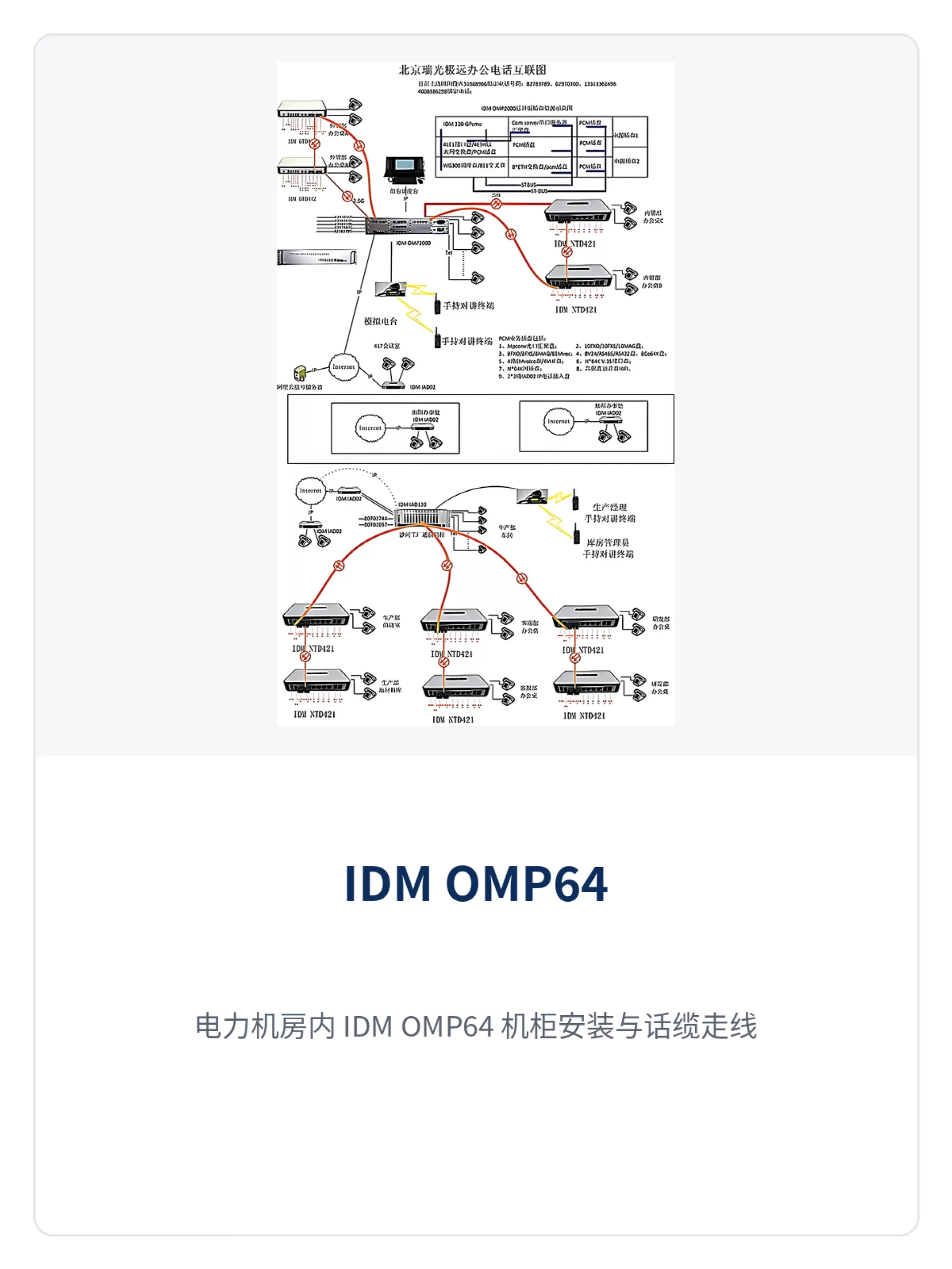
Figure 4: IDM OMP64 cabinet installation and telephone cable cabling in an electric power equipment room
Conclusion
As a 64-channel telephone dual-gigabit optical multiplexer, the IDM OMP64 packs 2.5G optical fiber bandwidth, 64 telephone channels and 2 physically isolated gigabit Ethernet (GE) interfaces into a single 2U enclosure, making it suitable for carrying voice and data over the same fiber in private network projects such as electric power, rail transit, military and government. During selection, determine the FXO-to-FXS ratio according to call direction, choose DC-48V or AC220V according to the on-site power distribution, and then reserve optical power margin according to link loss to finalize the configuration. Raytrans provides overall product showcase and selection support covering PDH, PCM equipment, integrated service access devices, optical transmission equipment and optical multiplexing equipment for government private network optical fiber communication solutions and military emergency communications vehicle solutions.