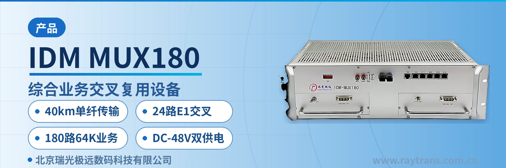
IDM MUX180 Integrated Service Cross-Connect Multiplexing Equipment
40 km single-fiber transmission
The IDM MUX180 Integrated Service Cross-Connect Multiplexing Equipment is an integrated service multiplexing platform that combines 64K narrowband service access, PCM multiplexing, 64K time-slot cross-connection, and SDH optical transmission. The IDM MUX180 equipment is mainly used for service access and cross-connection at the access layer of data communication networks. It provides complete synchronous timing functions, offers non-blocking cross-connection at the 64K level across up to 24 E1 channels, and can simultaneously provide 180 channels of 64K services, including telephone, magneto telephone, common battery telephone, and V.24 data services.
The IDM MUX180 155M optical port cross-connect multiplexing equipment is an integrated service multiplexing platform developed by Beijing Ruiguang Jiyuan Digital Technology Co., Ltd., integrating 64K narrowband service access, PCM multiplexing, 64K time-slot cross-connection, and 155M SDH optical transmission into a single unit. As a PCM equipment designed for the access layer, it is used for service access and cross-connection at the access layer of data communication networks, providing 180 channels of 64K services and implementing 64K-level non-blocking cross-connection within 24 E1 channels, combining the functional characteristics of time-slot cross-connect equipment and optical multiplexing equipment.
Access-layer sites often deploy PCM multiplexing, time-slot cross-connection, and optical transmission as three separate devices, which increases cabinet space usage, E1 patch cords, and common-ground interference. As an integrated service access device, the IDM MUX180 consolidates the three functions into a single chassis, so that service access, time slot allocation, and optical port uplink are completed within one configuration set. One less device layer at a site means one less point of failure, and it also provides a compact access-layer product showcase form for government private network optical fiber communication solutions and military emergency communications vehicle solutions.
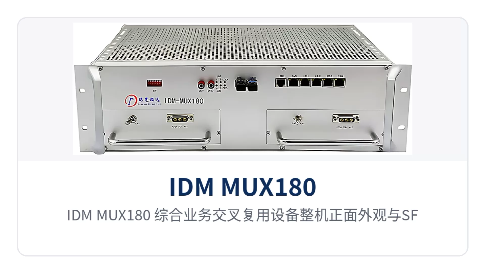
Figure 1: Front view of the IDM MUX180 Integrated Service Cross-Connect Multiplexing Equipment and close-up of the SFP optical port alarm indicator LED
Key Specifications at a Glance: 155M SFP optical port · 40 km single-fiber transmission · 24 E1 cross-connections · 180 channels of 64K services · receiver sensitivity better than -32 dBm · AC 220 V/DC -48 V dual power supply · overall power consumption ≤ 90 W
What is a 155M optical port cross-connect multiplexing equipment? One unit handles access, multiplexing, cross-connection, and transmission
The core of this type of PCM equipment is a 155.52 Mbps SDH optical channel plus a 64K cross-connect matrix. After narrowband services enter the chassis, they first land on the subscriber interface, enter the multiplexing unit by 64K time slot, are then assigned by the cross-connect unit to any one of the 24 E1 directions, and finally are sent onto the transmission line through the 155M optical port.
The optical port is an SFP slot, configured at the factory for single-mode 1310 nm/1550 nm, and can also be fitted with a multi-mode module for short-distance patching within an equipment room. The standard configuration provides 40 km single-fiber transmission; when station spacing exceeds this, a long-distance optical module can be fitted, with service configuration and network management methods unchanged.
The unit is a 19-inch rack-mounted structure measuring 482×309×132 mm, and can be installed in a standard cabinet and an integrated power cabinet. The front panel retains status indication for the optical path and E1 tributaries, so O&M personnel can read current alarms in front of the cabinet without opening the cover.
What can this equipment do: core functions at a glance
As an integrated service access device, the IDM MUX180 concentrates its capabilities in four areas: access, multiplexing, cross-connection, and transmission. The table below lists each function and its purpose; during selection, interface types and quantities can be checked against the project service point table. The table only describes functional boundaries; specific interface quantities and card types are finalized item by item against the point table during commercial confirmation.
| Function | Description |
|---|---|
| 64K narrowband service access | A single unit provides access capacity for 180 channels of 64K services, covering telephone, magneto telephone, common battery telephone, and V.24 data services |
| PCM multiplexing | Multiplexes voice channels and low-speed data into E1 channels according to the PCM30/32 frame structure, with channel-associated signaling, compatible with existing PCM networks |
| 64K time-slot cross-connection | Performs 64K-level non-blocking cross-connection within 24 E1 channels; any subscriber time slot can be assigned to any E1 time slot |
| 155M optical transmission | The SFP optical port uplinks to the optical line at 155.52 Mbps; standard configuration is 40 km single-fiber, extendable with a long-distance module |
| Synchronization timing | Complete synchronization timing functions; the clock can be derived from the line, an external 2 Mbit/s source, or the internal oscillator |
| Multi-service mixed insertion | Telephone, magneto, common battery, audio, V.24/V.35, and Ethernet interfaces configured in the same chassis according to the site point table |
| Dual power supply and wide-temperature operation | AC 220 V and DC -48 V power supply modes, operating from -20℃ to +50℃, suitable for unattended sites |
Key specifications: optical interface and E1 channels
Optical interface parameters determine how far a link can reach, while E1 parameters determine whether the equipment can interconnect with existing transmission networks. The values in the table below are taken from product technical documentation; for engineering calculations, on-site optical fiber attenuation and the number of connectors shall prevail. The values are equipment port specifications and exclude additional attenuation caused by patch cords, fiber adapters, and optical cable connectors.
| Item | Parameter/Specification | Description/Applicable Conditions |
|---|---|---|
| Interface type | SFP | Single-mode is standard; multi-mode optional |
| Receive/transmit rate | 155.52 Mbps | 155M SDH optical line rate |
| Receive/transmit wavelength | 1310 nm/1550 nm | Single-fiber bidirectional, configured in wavelength pairs |
| Transmit optical power | -12~-6 dBm | Determined by the selected optical module model |
| Receiver sensitivity | Better than -32 dBm | Receive threshold for link attenuation calculations |
| Transmission distance | 40 km | Standard configuration; long-distance optical modules available for longer reach |
The E1 side complies with ITU-T G.703 and can directly connect to the 2M tributaries of SDH, PDH, and PCM equipment. The 75 Ω and 120 Ω impedances are selected according to the on-site cabling method; changing over only involves interface adapters. The two access modes coexist on the same unit, so mixed-connection scenarios at legacy sites do not require an additional converter chassis.
| Item | Parameter/Specification | Description/Applicable Conditions |
|---|---|---|
| Bit rate | 2.048 Mbps | Complies with ITU-T G.703 |
| Line coding | HDB3 | Consistent with domestic E1 line formats |
| Impedance | 75 Ω/120 Ω | Coaxial and balanced access modes selected on site |
| Frame structure | PCM30/32 | Channel-associated signaling |
| Number of channels | 24 | Scope of 64K-level non-blocking cross-connection |
How to configure voice and data interfaces: parameter-by-parameter comparison
Voice interfaces cover 2-wire telephone, magneto telephone, common battery telephone, and audio services, with encoding uniformly using G.711 A-law at 64 Kbps. The table below lists audio range, impedance, and power feeding specifications; during configuration, select the card type according to the interface nature of the opposite-end telephone or exchange.
| Item | Parameter/Specification | Description/Applicable Conditions |
|---|---|---|
| Interface type | Telephone, magneto telephone, common battery telephone | Selected according to service nature and opposite-end equipment |
| Audio range | 300 Hz~3400 Hz | Transmission within the voice frequency band |
| Compression | ITU G.711 A-law | 64 Kbps voice encoding, interoperable with PCM networks |
| Impedance | Three-element complex impedance 200 Ω+560 Ω//0.1 μF | 2-wire telephone interface specification |
| Loop current | 20 mA/channel | Telephone power feeding current |
| Audio interface impedance | Balanced 600 Ω | 2-wire/4-wire audio and broadcast services |
| Return loss | No less than 18 dB | Balanced 600 Ω audio interface specification |
The data interface side provides Ethernet, V.24, and V.35 simultaneously; Ethernet bandwidth is configured in VC12 granularity, and low-speed data is carried in point-to-point mode. The asynchronous and synchronous operating modes cover the common rates of telecontrol, monitoring, and routers.
| Item | Parameter/Specification | Description/Applicable Conditions |
|---|---|---|
| Ethernet interface | RJ-45 | Complies with IEEE 802.3, full/half duplex adaptive |
| Ethernet bandwidth | N×VC12 (N≤50) | Configured by number of VC12s, sharing the optical channel with narrowband services |
| V.24 asynchronous mode | Rate adaptive up to 38.4 kbps | Electrical characteristics comply with CCITT V.28 |
| V.24 synchronous mode | 300 bps~128 kbps | Covers common rates such as 2.4k, 9.6k, and 64k |
| V.35 interface | n×64 Kbps (n=0~31) | Complies with ITU-T V.35; terminal interface complies with ISO2593 |
24 E1 cross-connections and 180 channels of 64K services: how one unit replaces multiple units
The value of 64K time-slot cross-connect equipment lies in decoupling service assignment from cabling. One E1 provides 32 64K time slots according to PCM30/32, and 24 E1 channels total 768 time slots, far more than the 180-channel interface capacity of a single unit. Therefore, any telephone or data channel can be assigned to any time slot of any E1, and service adjustment only requires changing the configuration.
- After in-station voice channels are accessed, they are mapped to E1 time slots according to the point table; cross-direction scheduling does not require touching the patch cords behind the chassis;
- Ethernet services occupy bandwidth as N×VC12 and coexist with 64K narrowband services in the same optical channel;
- When adding sites or adding sections, capacity expansion only requires additional interface cards; the cross-connect matrix and optical port need not be replaced;
- The 24 E1 directions can serve as uplink channels to different aggregation nodes, forming chain or star topologies.
For O&M, what this mechanism reduces is the number of on-site rewiring operations. Service adjustment changes from "sending someone to the site to rearrange the patch panel" to "modifying a time slot table on the network management system," and the change record is likewise kept in the configuration and is traceable afterwards. Channel adjustment no longer requires applying for a power outage window and can be completed on the network management side at night.
Typical application scenarios
The IDM MUX180 targets private network scenarios that use E1 and optical channels as the backbone and need to aggregate voice and low-speed data, with electric power, rail transit, and military and government private networks as the main deployment directions; chain networks, star networks, and point-to-point structures are all organized according to site distribution. As a product integrating the functions of PCM equipment, integrated service access device, and time-slot cross-connect equipment, its typical networking capabilities in the product showcase are as follows.
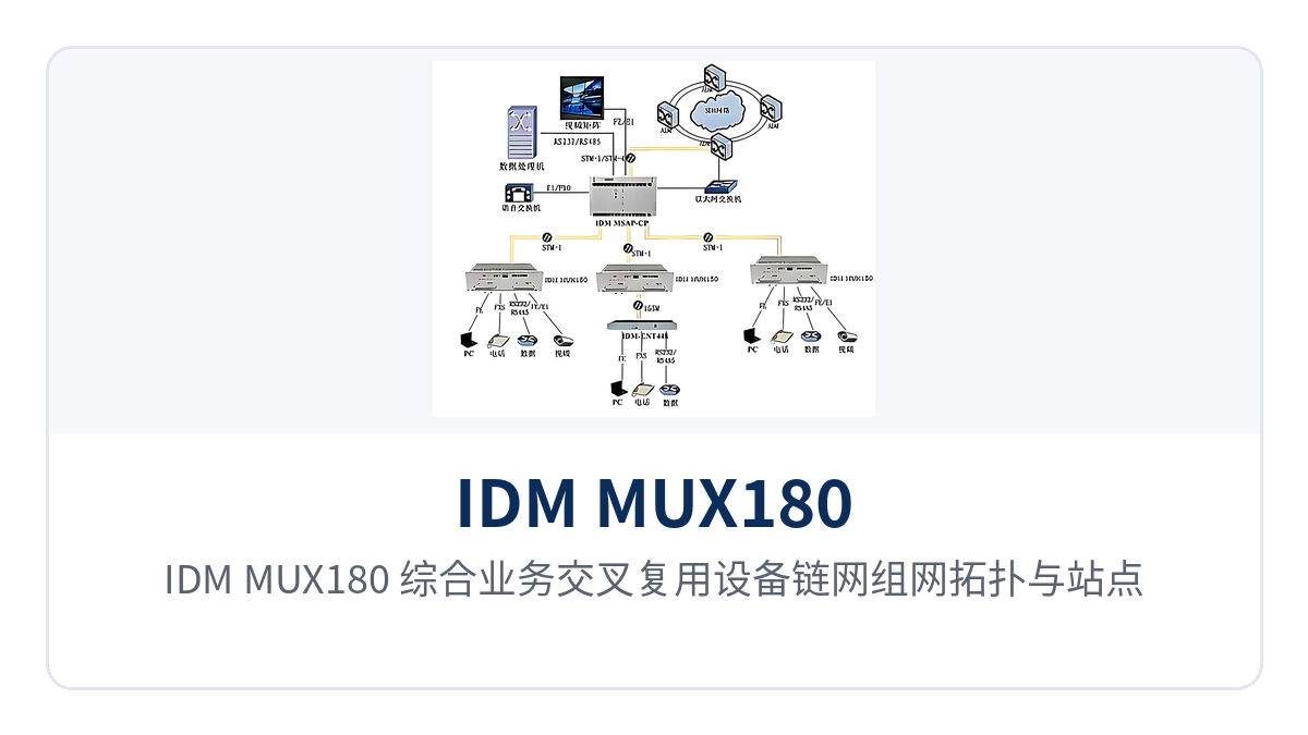
Figure 2: Chain network topology and site interface configuration of the IDM MUX180 Integrated Service Cross-Connect Multiplexing Equipment
Electric power private network: simultaneous voice and telecontrol transmission between substations and dispatch centers
Between substations and switching stations and the dispatch center, both dispatch telephone and low-speed data for telecontrol and electric energy acquisition are carried. The IDM MUX180 accesses voice channels and V.24 data separately within the station, uses 24 E1 cross-connections to send different services to channels in different directions, and carries voice and telecontrol simultaneously over one optical fiber, fully demonstrating the service scheduling value of time-slot cross-connect equipment in electric power private networks.
When only a DC distribution panel is available in the station, DC -48 V power is used; when AC power is available, AC 220 V is used; both modes are selectable on the same model. Overall power consumption is ≤ 90 W, and the -20℃~+50℃ operating range covers outdoor integrated power cabinets, so storage battery backup time is not noticeably shortened by the access equipment.
Rail transit: service aggregation for stations along the line and section equipment
Distances between stations along the line, traction substations, and section equipment rooms in rail transit are measured in kilometers, and services are mainly inter-station telephone, broadcast audio, and equipment monitoring data. The IDM MUX180 uses 155M optical ports to string adjacent stations into a chain network, so section stations do not need a separate transmission device; the combined design of optical multiplexing equipment and PCM reduces the number of cabinets along the line.
The 600 Ω audio interfaces for inter-station hotline telephone and section broadcast are implemented in the same unit, with audio interface return loss no less than 18 dB, making it easier to maintain voice clarity on long-distance voice channels in daily dispatching. Section equipment monitoring data goes through V.24 interfaces and shares the same optical channel with voice.
Military and government private networks: long-distance access for unattended field nodes
Power supply conditions at field sites are complex, with mains power, diesel generators, and solar DC coexisting, and sites are often unattended for long periods. The AC 220 V/DC -48 V dual power supply and -20℃~+50℃ operating range allow the same model to be installed in cabinets with different power supply modes, so only one type of spare part is needed, meeting the equipment environmental adaptability requirements of military emergency communications vehicle solutions.
With 40 km single-fiber transmission and receiver sensitivity better than -32 dBm, no repeater is usually needed between adjacent sites; for longer links, a long-distance optical module can be fitted, with the network management channel and service configuration unchanged, so the upgrade does not affect already-enabled voice channels. One repeater equipment room and its supporting power supply can therefore be eliminated at field sites. For government private network optical fiber communication solutions, this long-distance access capability likewise reduces investment in repeater nodes.
Selection and deployment points: five checks
Configuration differences for access layer equipment mainly fall into five areas: optical ports, the number of E1 directions, interface point tables, power supply format, and clock source. Check each item before placing an order to avoid rework after delivery. The following five items are arranged in construction order; the interface point table and power supply format should be confirmed in step with the equipment room renovation.
- Optical ports and distance: Select 40 km standard modules or long-distance modules according to the actual inter-station optical fiber length, and determine single-mode versus multi-mode based on the existing network's fiber.
- Number of E1 directions: Determine according to the number of 2M channels available from the upstream SDH equipment manufacturer or PDH; 24 channels is the unit's maximum capacity.
- Service interface point table: Configure cards for telephones, magneto, common battery, V.24/V.35, and Ethernet according to the point table; for magneto and common battery, the opposite-end type must be specified.
- Power supply format: Check whether the equipment room has a -48V DC distribution panel; confirm the wiring method for dual power supply and the protective ground before construction.
- Clock and network management: Specify whether the clock is derived from the line or from an external 2Mbit/s source; whether the network management channel uses DCC or E1 time slots must be aligned with the upstream network management.
Conclusion
Access layer selection ultimately comes down to three things: whether the link can be extended, whether services can be provisioned, and whether the site can operate unattended over the long term. As a 155M optical port cross-connect multiplexing equipment, the IDM MUX180 uses single-fiber 40 km transmission to solve remote extension, 24-channel E1 non-blocking cross-connection to solve dispatching, and AC220V/DC-48V dual power supply with wide-temperature design to solve unattended operation, bringing all three types of issues together in one device. As a professional optical multiplexer manufacturer and SDH equipment manufacturer, Raytrans continues to invest in the integrated service access capability of this product series, providing reliable PCM equipment and optical multiplexing equipment support for various private networks.
For projects in electric power, rail transit, and military and government private networks, one device simultaneously handles access, multiplexing, and cross-connection, reducing the number of cabinets, power distribution circuits, and the variety of spare parts, making construction and O&M costs at the access layer easier to calculate. With unified models, cross-line transfers and spare parts sharing also become simpler.