IDM MTP
IDM MTP
The Field Intelligent Multi-Service Optical Transmission Equipment adopts modular functional design, including SDH optical transmission unit, E1 link interface control unit, EOS unit, PCM unit, SNMP unit, and protection switching unit. It features shockproof, waterproof, and electromagnetic compatibility chassis design, and the service interfaces provided are suitable for military field use. In addition to the standard configuration of 4 channels of 10/100M Ethernet, 16 channels of E1, 16 channels of 2-wire and 4 channels of 4-wire voice, 1 channel of V.35, 2 channels of V.24, 1 channel of E1 link and 1 channel of V.35 channel, the equipment also has 4 expansion slots for inserting various service cards.
1. Overview
In response to the needs of military field operations, Beijing Ruiguang Jiyuan Digital Technology Co., Ltd. has launched the Field Intelligent Multi-Service Optical Transmission Equipment series. The Field Intelligent Multi-Service Optical Transmission Equipment is developed using internationally advanced integrated circuits, programmable logic circuits, and high-speed microprocessors. It multiplexes E1 signals, audio signals, telephone/magneto signals, and line-rate 100M Ethernet signals for transmission over STM-4 (622Mbit/s) optical fiber and E1 channels, supporting intelligent mutual backup of transmission channels between STM-4 optical fiber and E1 links.
The IDM MTP-622 Field Intelligent Multi-Service Optical Transmission Equipment is specifically designed for military field communications. The equipment adopts modular functional design, including SDH optical transmission unit, E1 link interface control unit, EOS unit, PCM unit, SNMP unit, and protection switching unit. It features shockproof, waterproof, and electromagnetic compatibility chassis design, and the service interfaces provided are suitable for military field use. In addition to the standard configuration of 4 channels of 10/100M Ethernet, 16 channels of E1, 16 channels of 2-wire and 4 channels of 4-wire voice, 1 channel of V.35, 2 channels of V.24, 1 channel of E1 link and 1 channel of V.35 channel, the MTP-622 Field Intelligent Multi-Service Optical Transmission Equipment also has 4 expansion slots for inserting various service cards.

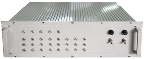
Front View of Equipment

Rear View of Equipment
2. Functional Features
1) Standard 19-inch 3U chassis structure design;
2) Modular system design with universal service access slots, allowing access to various required services according to user configuration requirements;
3) Supports intelligent mutual backup between E1 links and SDH optical links;
4) Supports local telephone switching function, supports 1~2 E1 digital trunk interfaces (supporting No.7, PRI, and No.1 signaling);
5) Supports SNMP network management protocol, supports service configuration of remote equipment; supports northbound interface for uploading alarm information;
6) Supports dual hot backup of power supply; supports replaceability of optical ports;
7) Supports STM4 optical interfaces, E1 services, FXS/FXO services, magneto services, V.24 services, V.35 services, and Ethernet services;
8) Provides E1 link interface;
9) Provides five-in-one 2-wire audio card: each card provides 16 channels of 2-wire audio, each channel can be configured as FXO/FXS/hotline/magneto/2100 magneto mode;
10) All interfaces are designed with aviation plug type;
11) The equipment EMC design complies with the relevant provisions for army ground equipment in GJB151A-1997 "Electromagnetic Emission and Susceptibility Requirements for Military Equipment and Subsystems", and the electromagnetic emission and susceptibility tests comply with the relevant provisions in GJB152A-1997 "Measurement of Electromagnetic Emission and Susceptibility for Military Equipment and Subsystems";
12) The equipment meets the vibration requirements in GJB367A-2001 "General Specification for Military Communication Equipment", the shock requirements in GJB367A-2001 "General Specification for Military Communication Equipment", and the drop requirements in GJB367A-2001 "General Specification for Military Communication Equipment";
13) The equipment has good waterproof and moisture-proof design.
3. Main Tactical Technical Specifications
1) Optical fiber line interface
Quantity: 2; Rate: 622Mbit/s; Characteristics: Complies with ITU-T G.957 standard.
2) E1 link interface
Quantity: 1; Rate: 2.048Mbps; Characteristics: Complies with ITU-T G.703 standard.
3) Service interfaces:
E1 circuit interface
Quantity: 16 (75Ω, unbalanced); Rate: 2.048Mbps; Characteristics: Complies with ITU-T G.703 standard.
Ethernet interface
Quantity: 4; Rate: 10M/100M auto-negotiation; Characteristics: Complies with IEEE802.3 standard.
V.35 interface
Quantity: 1; Rate: N×64Kbit/s (n≤30); Characteristics: Complies with ITU-T V.35 standard.
RS232 interface
Quantity: 2; Rate: ≤19.2Kbit/s; Characteristics: Complies with EIA RS232 standard.
2-wire/4-wire voice interface
Quantity: 20 channels (4 channels 4-wire, 16 channels 2-wire); Rate: 64Kbit/s; Modes: hotline, magneto, subscriber, trunk.
4) Order wire interface: 1;
5) Synchronization clock interface: 1 pair, including 1 external input clock interface and 1 output synchronization clock interface.
6) Management interface
Interface characteristics: Complies with relevant provisions of IEEE 802.3;
Interface communication protocol: SNMP.
7) The network management system provides northbound interface, with the capability to access the military-wide optical fiber communication transmission network management system;
8) Switching time of 2M services from optical cable link to E1 link: ≤50ms (using hot backup mode), ≤15s (using dial-up mode to establish E1 link), ≤50s (using integrated network management mode to establish E1 link);
9) Error performance: Optical fiber link complies with relevant provisions of ITU-T G.826;
10) Equipment power supply: AC and DC power supply modes;
11) Equipment dimensions: Height ≤3U, installable in 19-inch standard rack.
4. Technical Specifications
4.1 Optical Interface Technical Parameters
Interface type: SFP (hot-swappable); Fiber mode: Single-mode (multi-mode optional)
Rate: 622Mbit/s; Wavelength: 1310nm or 1550nm
Transmit power: -15~-8dBm; Receiver sensitivity: Better than -32dBm
Transmission distance: 40Km, optional long-distance optical modules for longer fiber transmission.
4.2 E1 Interface Technical Parameters
Line code: HDB3; Rate: 2048Kbps±50ppm
Impedance: 70Ω (unbalanced); Frame structure: PCM31/30; Signaling: Channel-associated signaling; Jitter characteristics: Complies with ITU-T G.823; Standard protocol: Supports ITU-T G.703/G.704; Frame mode: Framed/unframed configurable, timeslots configurable
4.3 Ethernet Interface Technical Parameters
Interface type: RJ45; Rate: 10M/100M selectable
Standard protocol: Supports IEEE802.3 standard; Working mode: Half/full duplex
4.4 Automatic Telephone Interface Technical Parameters
FXS interface performance indicators
Frequency band: 300~3400 Hz; Impedance: (200Ω+560Ω//104)
Loop resistance: <2KΩ; Receive level: -3.5dBr
Transmit level: 0 dBr; Idle channel noise: <-65 dBmop
Crosstalk: ≤-65 dBmop
FXO interface performance indicators
Frequency band: 300~3400 Hz; Impedance: (200Ω+680Ω//104)
Transmit level: 0 dBr; Receive level: -3.5dBr
Crosstalk: ≤-65 dBmop; Idle channel noise: <-65 dBmop
4.5 Magneto Telephone/2100Hz Magneto Telephone Interface Specifications
Frequency band: 300~3400 Hz; Impedance: 600Ω
Transmit level: 0 dBr; Receive level: -3.5dBr
Crosstalk: ≤-65 dBmop; Idle channel noise: <-65 dBmop
4.6 Hotline Telephone Interface Specifications
Frequency band: 300~3400 Hz; Impedance: 600Ω
Loop resistance: <2KΩ; Receive level: -3.5dBr
Transmit level: 0 dBr; Idle channel noise: <-65 dBmop
Crosstalk: ≤-65 dBmop
4.7 RS232/RS485 Interface Specifications
Asynchronous rate: <=19.2K auto-adaptive; Synchronous rate: 64K
Interface: Meets ITU-T RS232 and ITU-RS485 interface standards
4.8 V35 Interface Specifications
Rate: N*64K N<=32; Mode: Supports DCE and DTE modes
Interface: Meets ITU-T V35 interface standard
5. Environmental Specifications
5.1 Operating/Storage Environment
Temperature (°C): -25°C to 55°C
Storage temperature: -40°C to 75°C
Relative humidity (%): ≤95%, non-condensing
5.2 Power Supply Requirements
The equipment uses AC 220V and DC -48V/DC 24V power input.
AC voltage: 187V~253V
DC voltage: DC -38V~-58V / DC -19V~-28V
6. Application Example

In the application scheme, one IDM Intelligent Multi-Service Optical Transmission Equipment is configured at the central office and remote site respectively. The transmission line uses 622M (STM-4) and E1 link mutual backup transmission channels. The central office can access the telephone switching network through FXO analog trunk or E1 digital trunk, and access the IP network through Fast Ethernet interface, while providing access to V.35, V.24, hotline telephone, ordinary telephone, E1, and 4-wire audio services.
The remote equipment can be deployed at field training bases or installed on field communication vehicles, providing access to V.35, V.24, hotline telephone, ordinary telephone, E1, 4-wire audio services, and Ethernet services.
When the optical fiber transmission channel is in good condition, all services are transmitted through 622M optical fiber, where Ethernet service bandwidth is configured with 2M granularity, providing N×2M high-bandwidth Ethernet service transmission; when the optical fiber fails, the equipment automatically switches to the E1 link channel, realizing transmission of specified 64K and N×64K services on the E1 channel, where Ethernet service bandwidth is configured with 64K granularity, providing N×64K low-bandwidth Ethernet service transmission. When the optical fiber channel fault recovers, the equipment automatically switches all services back to optical fiber transmission.
FAQs
What are common issues when using optical terminals in security surveillance?
Fiber optic technology is increasingly used in security surveillance projects to transmit images, audio, data…
View answerWhat Are the Functions and Advantages of Video Optical Terminals?
The function of a video optical terminal is to convert one or multiple channels of analog video signals into optical…
View answer